
Related Manuals for Fujitsu DD2963-S


Summary of Contents for Fujitsu DD2963-S
- Page 1 Mini-ITX D2963-S Mini-ITX D2963-S TechNotes V1.0 First Release Mainboard OEM Sales - 01/2010...
-
Page 2: Table Of Contents
à Page 66 • Mainboard Power Consumption à Page 68 • Special Features à Page 71 • Operating System Support • OEM FTP download link for D2963-S ftp://ftp.ts.fujitsu.com/pub/Mainboard-OEM-Sales/Products/Mainboards/Industrial&ExtendedLifetime/D2963-S/ (provides BIOS; Drivers; Documents & Approvals; Specifications; Tools etc.) TechNotes_D2963_V1.0 Copyright 2010 FUJITSU LIMITED... -
Page 3: Safety Instructions
(except for the rear I/O connectors) until the mainboard is completely powered down. Any damage caused to the mainboard by misuse of the onboard connectors is excluded from the standard warranty. Fujitsu Technology Solutions cannot be held liable for any damage that results from incorrect use of any onboard connectors. - Page 4 Overview • Onboard interfaces & connectors TechNotes_D2963_V1.0 Copyright 2010 FUJITSU LIMITED...
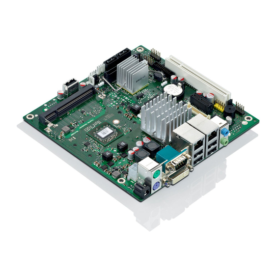
- Page 5 Overview Overview Onboard Components Onboard Components Stereo Audio In/Out Dual-LAN / 4 x USB 2.0 COM1 / DVI-I 2 x PS/2 PCB: 8-layer DC-IN (+ 19…24V) TechNotes_D2963_V1.0 Copyright 2010 FUJITSU LIMITED...
- Page 6 2 x SATA II Drive Power Connector 2 x 2 USB Ports 1 x SO-DIMM LVDS-Backlight Frontpanel GPIO Port Processor CPU Fan 24 Bit Dual Channel LVDS PCIe X1 Frontpanel Audio 19…24V DC-In Buzzer COM 2 TechNotes_D2963_V1.0 Copyright 2010 FUJITSU LIMITED...
- Page 7 Overview Overview Onboard Components Onboard Components Mini PCI Express Connector (incl. USB support) Mechanical Lock for Mini PCI Express Card Sample for WLAN Minicard on D2963-S Mechanical Lock (supports fullsize cards only!) TechNotes_D2963_V1.0 Copyright 2010 FUJITSU LIMITED...
- Page 8 1.0GHz / 256KB L2 / 8W TDP Intel Atom N270/945GSE 1.6GHz / 512KB L2 / 2.5W TDP System configuration: 2 x 512MB @ max. memory speed 1) Intel Atom and D2963-S: 1 x 1GB (1 socket only) TechNotes_D2963_V1.0 Copyright 2010 FUJITSU LIMITED...
- Page 9 1.0GHz / 256KB L2 / 8W TDP Intel Atom N270/945GSE 1.6GHz / 512KB L2 / 2.5W TDP System configuration: 2 x 512MB @ max. memory speed 1) Intel Atom and D2963-S: 1 x 1GB (1 socket only) TechNotes_D2963_V1.0 Copyright 2010 FUJITSU LIMITED...
- Page 10 1.0GHz / 256KB L2 / 8W TDP Intel Atom N270/945GSE 1.6GHz / 512KB L2 / 2.5W TDP System configuration: 2 x 512MB @ max. memory speed 1) Intel Atom and D2963-S: 1 x 1GB (1 socket only) TechNotes_D2963_V1.0 Copyright 2010 FUJITSU LIMITED...
-
Page 11: Display Options
Display Options • LVDS display & backlight inverter • LVDS / Inverter connector details • LVDS timings & screen resolutions • LVDS cabling reference • DVI, VGA, HDMI, LVDS TechNotes_D2963_V1.0 Copyright 2010 FUJITSU LIMITED... - Page 12 Display Options Display Options LVDS Display & Backlight Inverter LVDS Display & Backlight Inverter Integrated Backlight, powered by Inverter Backlight Inverter LVDS Display (rear view) Integrated Backlight, powered by Inverter TechNotes_D2963_V1.0 Copyright 2010 FUJITSU LIMITED...
- Page 13 Display Options Display Options LVDS Display & Backlight Inverter LVDS Display & Backlight Inverter Integrated Backlight, powered by Inverter Backlight Inverter LVDS Display (rear view) Integrated Backlight, powered by Inverter LVDS Data / Power for display TechNotes_D2963_V1.0 Copyright 2010 FUJITSU LIMITED...
- Page 14 Display Options Display Options LVDS Display & Backlight Inverter LVDS Display & Backlight Inverter Integrated Backlight, powered by Inverter Backlight Inverter LVDS Display (rear view) Integrated Backlight, powered by Inverter LVDS Data / Power for display TechNotes_D2963_V1.0 Copyright 2010 FUJITSU LIMITED...
- Page 15 LVDS_CLK_L- (CLK_ODD-) Ground Ground LVDS voltage selector jumper DDC-Data DDC-Clock LCD-Power LCD-Power Ground LCD-Power Signal 3.3V (default) LCD_Power_Enable Ground VCC 3.3V 5V (optional) 1) selectable via Jumper Power LVDS max. load: 1A per pin! VCC 5V TechNotes_D2963_V1.0 Copyright 2010 FUJITSU LIMITED...
- Page 16 Backlight On/Off Control: Active High, 3.3V Note: Polarity can be changed via BIOS Setup (Not supported by pilot production mainboards GS5x!) TechNotes_D2963_V1.0 Copyright 2010 FUJITSU LIMITED...
- Page 17 LVDS screen resolution: 2048 x 1536 / 32bit color Note: Default BIOS Setting for LVDS is “Disabled”. Any BIOS Setup changes can be fixed as new default BIOS setting via BIONVD tool! ftp://ftp.ts.fujitsu.com/pub/Mainboard-OEM-Sales/Services/Software&Tools/Common-Mainboard-Tools/ChangeBIOS-Setup-Defaults/ TechNotes_D2963_V1.0 Copyright 2010 FUJITSU LIMITED...
- Page 18 Advanced \ Peripheral Configuration LCD Parameter setup --> User Defined • Save settings and reboot system • Note: In order to remove the "User defined" LVDS setting in BIOS Setup, run the DOS Batch-File "Remove.bat" TechNotes_D2963_V1.0 Copyright 2010 FUJITSU LIMITED...
- Page 19 1024 x 768 TDK CXA-0349 15" AUO G150XG01V0 1024 x 768 Green-C&C GH001A-ROHS 17" AUO M170EG01-VD 1280 x 1024 Green-C&C GH053A-ROHS 19" Sharp LQ190E1LW01 1280 x 1024 Power Systems PS-DA0412-05 19" AUO M190EG01 1280 x 1024 GH053(A1)-ROHS TechNotes_D2963_V1.0 Copyright 2010 FUJITSU LIMITED...
- Page 20 Display Options Display Options LVDS Sample Cabling for AuO-G150 LVDS Sample Cabling for AuO-G150 TechNotes_D2963_V1.0 Copyright 2010 FUJITSU LIMITED...
- Page 21 Digital (DVI) Monitor max. DVI screen resolution: 2560 x 1600 / 32bit color (Dual Link) 1600 x 1200 / 32bit color (Single Link, standard timings) 1920 x 1200 / 32bit color (Single Link, reduced blanking timings) TechNotes_D2963_V1.0 Copyright 2010 FUJITSU LIMITED...
- Page 22 Display Options Display Options HDMI Output (w/o audio!) HDMI Output (w/o audio!) Digital (HDMI) Monitor via DVI/HDMI interface connector max. HDMI screen resolution: 1080i Note: Only HDMI graphics supported, no audio transmission! TechNotes_D2963_V1.0 Copyright 2010 FUJITSU LIMITED...
- Page 23 VGA Output via Interface Connector VGA Output via Interface Connector Analog (VGA) Monitor via DVI/VGA interface connector max. VGA screen resolution: 2048x1536 @85Hz for 4:3 format 2560x1440 @75Hz for 16:9 format 2456x1536 @60Hz for 16:10 format TechNotes_D2963_V1.0 Copyright 2010 FUJITSU LIMITED...
- Page 24 DVI & VGA via Splitter Cable DVI & VGA via Splitter Cable Analog (VGA) Monitor and Digital (DVI) Monitor via DVI/VGA splitter cable Dual Independent Display Option (Note: DVI – single link only via splitter cable!) TechNotes_D2963_V1.0 Copyright 2010 FUJITSU LIMITED...
- Page 25 Display Options DVI or VGA plus LVDS DVI or VGA plus LVDS Analog (VGA) Monitor or Digital (DVI) Monitor; plus LVDS Display Dual Independent Display Option max. LVDS screen resolution: 2048 x 1536 / 32bit color TechNotes_D2963_V1.0 Copyright 2010 FUJITSU LIMITED...
-
Page 26: Power Supply Features
Power Supply Features • 19-24V DC power supply • Drive power connector TechNotes_D2963_V1.0 Copyright 2010 FUJITSU LIMITED... - Page 27 Power Supply Features D2963-S offers two power supply options 1. Onboard 4 - pin power supply connector Pin 1, 2: GND Pin 3, 4: +19…24V DC-In Pin 1, 2: GND Pin 3, 4: +19…24V DC-In TechNotes_D2963_V1.0 Copyright 2010 FUJITSU LIMITED...
- Page 28 GND (Ø 6.4mm) +19…24V DC (Ø 2.5mm) Appropriate DC plug for external AC adapter: Note: “Universal Plug” not allowed due to possible polarity mismatch! Ø 2.5mm / 5.5mm contact length ~ 10-11mm Angle plug or straight plug TechNotes_D2963_V1.0 Copyright 2010 FUJITSU LIMITED...
- Page 29 PCI/PCIe- connector, USB- connectors, GPI/O, backlight-connector, and drive power connector is limited! Max. overall output current: +3.3V / 5A +5V / 4.5A +12V / 2.5A -12V / 0.1A See mainboard specification for further details! TechNotes_D2963_V1.0 Copyright 2010 FUJITSU LIMITED...
- Page 30 Power option for internal drives Power option for internal drives 19/24V AC 19/24V Adapter Supply (external) (internal) Drive Power Connector 2.5” HDD optional: SATA CD/DVD Max. rating via Drive Power Connector: +5V/2A ; +12V/2A BLUE = power TechNotes_D2963_V1.0 Copyright 2010 FUJITSU LIMITED...
- Page 31 Power option for internal drives 19/24V AC 19/24V Adapter Supply (external) (internal) Drive Power Connector 2.5” HDD optional: SATA CD/DVD Max. rating via Drive Power Connector: +5V/2A ; +12V/2A RED = data BLUE = power TechNotes_D2963_V1.0 Copyright 2010 FUJITSU LIMITED...
- Page 32 Power Supply Features Power Supply Features Drive Power Connector Drive Power Connector Drive Power Connector VCC (+5V) max. 2A Note: Connector is compliant to standard floppy power supply connector. +12V max. 2A TechNotes_D2963_V1.0 Copyright 2010 FUJITSU LIMITED...
- Page 33 Conn. 1 Conn. 2 Conn. 3 Note 7, 8, 9 2, 3 +5V, red 4, 5, 6 5, 6 GND, black 10, 11, 12 GND, black Cable Ordercode: 13, 14, 15 +12V, yellow T26139-Y1500-V700 TechNotes_D2963_V1.0 Copyright 2010 FUJITSU LIMITED...
- Page 34 Additional Power Output via Inverter Connector Additional Power Output via Inverter Connector Prerequisite: No LVDS display attached to mainboard! The backlight inverter connector provides additional power for internal devices (+5V / +12V; max. 2A per pin!) TechNotes_D2963_V1.0 Copyright 2010 FUJITSU LIMITED...
- Page 35 Power Supply Features Power Supply Features Additional Power Output via Feature Connector Additional Power Output via Feature Connector Feature Connector provides additional power for internal devices: 3.3V 5Vaux max. 1.5 A per pin! Feature Connector TechNotes_D2963_V1.0 Copyright 2010 FUJITSU LIMITED...
-
Page 36: Internal Connectors
Internal Connectors • Optional Devices via Feature Connector • Internal USB/Audio Ports • Compact Flash • Second Serial Port • Frontpanel Connector • PCI / PCIe / Mini-PCIe Extension Slot TechNotes_D2963_V1.0 Copyright 2010 FUJITSU LIMITED... - Page 37 (3.3V; 5V; 12V; 5Vaux; max. 1A per pin!) 8 bit 3.3V General Purpose Input/Output (GPIO) in order to attach any digital device (sample picture) IrDA Transceiver Feature (sample picture) Connector TechNotes_D2963_V1.0 Copyright 2010 FUJITSU LIMITED...
- Page 38 GPIO features (included in SystemMonitoring API) GPI/O Output High Voltage min. 2.4V Available via OEM FTP Server: Input Leakage Current max. +/- 10µA ftp://ftp.ts.fujitsu.com/pub/Mainboard-OEM- Note: max. load per GPI/O pin: 8mA Sales/Products/Mainboards/Industrial&ExtendedLifetime/D2963- S/IndustrialTools_D2963-S/BMC_Management-Controller-API/ TechNotes_D2963_V1.0 Copyright 2010 FUJITSU LIMITED...
- Page 39 Internal Connectors Internal Connectors Internal USB/Audio Ports Internal USB/Audio Ports Connect internal ports to USB/ Audio frontpanel module (Note: 2 USB ports per connector) USB Ports Frontpanel RED = USB Audio BLUE = Audio TechNotes_D2963_V1.0 Copyright 2010 FUJITSU LIMITED...
- Page 40 Internal Connectors Internal Connectors Internal USB Ports – Miscellaneous Options Internal USB Ports – Miscellaneous Options Optional: Touchscreen Controller via USB USB Ports TechNotes_D2963_V1.0 Copyright 2010 FUJITSU LIMITED...
- Page 41 Internal Connectors Internal Connectors Internal USB Ports – Miscellaneous Options Internal USB Ports – Miscellaneous Options Optional: Touchscreen Controller via USB Optional: Attach USB Flash Disk Module USB Ports (up to 8GB available) e.g. www.stec-inc.com TechNotes_D2963_V1.0 Copyright 2010 FUJITSU LIMITED...
- Page 42 Internal Connectors Internal Connectors Compact Flash Compact Flash CF Card – inserted in socket on mainboard (IDE „Master“-Interface) TechNotes_D2963_V1.0 Copyright 2010 FUJITSU LIMITED...
- Page 43 Internal Connectors Internal Connectors Second Serial Port Second Serial Port Note: Pinning according FTS standard! External I/O Bracket COM2 Connector TechNotes_D2963_V1.0 Copyright 2010 FUJITSU LIMITED...
- Page 44 Internal Connectors Internal Connectors Frontpanel Connector Frontpanel Connector Frontpanel providing - Powerswitch - Power/HDD-LED - Reset-Switch Frontpanel Connector TechNotes_D2963_V1.0 Copyright 2010 FUJITSU LIMITED...
- Page 45 100R series resistor HDD LED: 5.0V supply max. 10mA onboard 330R series resistor Frontpanel Connector (KEY) Reserved (NC) PowerSwitch_GND ResetSwitch_P PowerSwitch_P ResetSwitch_GND Power_LED_GND HDD_LED- Note: Pinning is compatible to Power_LED+ HDD_LED+ Intel 10 pin header TechNotes_D2963_V1.0 Copyright 2010 FUJITSU LIMITED...
- Page 46 - 32Bit, 33MHz, PCI Rev. 2.3 - Compliant to 3.3V / 5V devices - Supports up to two PCI master slots via risercards PCI Risercards offered by FTS Note: Third party risercards must not use any “Reserved”-pins of PCI connector! TechNotes_D2963_V1.0 Copyright 2010 FUJITSU LIMITED...
- Page 47 Internal Connectors PCI Express Extension Slot PCI Express Extension Slot - PCIe x1 - Provides the option to install customer-specific extension cards - Note: External connectors of PCIe x1 cards require appropriate aperture in chassis rear! TechNotes_D2963_V1.0 Copyright 2010 FUJITSU LIMITED...
- Page 48 Mini PCI Express Extension Slot (bottom side) Mini PCI Express Extension Slot (bottom side) Mini PCI Express Connector (incl. USB support) Mechanical Lock for Mini PCI Express Card Note: Mini card lock supports full length cards only! TechNotes_D2963_V1.0 Copyright 2010 FUJITSU LIMITED...
-
Page 49: System Monitoring
System Monitoring • Temperature Sensors and Fans • SystemGuard: Fan/Temperature Monitor • SilentFanConfig: Customize System Monitoring • Temperature Reference Points TechNotes_D2963_V1.0 Copyright 2010 FUJITSU LIMITED... - Page 50 D2963-S: Fans FAN 1 (CPU Fan) FAN 2 (Chassis) Note: Fan1 PWM (4-wire) only! Fan2: PWM (4-wire) and voltage controlled (3-wire) possible. Selectable via BIOS Setup Note: Do not attach more than one fan per connector! TechNotes_D2963_V1.0 Copyright 2010 FUJITSU LIMITED...
- Page 51 System Monitoring System Monitoring D2963-S: Temperature Sensors D2963-S: Temperature Sensors CPU Sensor (inside Processor) Sensor 2 (inside Northbridge) Sensor 1 (inside Super I/O) TechNotes_D2963_V1.0 Copyright 2010 FUJITSU LIMITED...
- Page 52 ~ 6V; the maximum operating voltage (full speed) is 12V. Note: If a 3-wire fan is used while BIOS Setup is set to “4-Wire”, the fan will operate at full speed (=12V operating voltage)! TechNotes_D2963_V1.0 Copyright 2010 FUJITSU LIMITED...
- Page 53 • SystemGuard offers several options like “LogFile- feature” and “No Adjustments- mode” Details are available here: ftp://ftp.ts.fujitsu.com/pub/Mainboard-OEM-Sales/Services/Software&Tools/Common-Mainboard-Tools/SystemGuard/Documentation/ Note: A Windows-based API is available for easy implementation of the • System Monitoring features like fan speed, sensor temperatures etc. ftp://ftp.ts.fujitsu.com/pub/Mainboard-OEM-Sales/Products/Mainboards/Industrial&ExtendedLifetime/D2963-S/IndustrialTools_D2963- S/BMC_Management-Controller-API/ TechNotes_D2963_V1.0 Copyright 2010 FUJITSU LIMITED...
- Page 54 1) Note: Characteristics for FAN1 is always dependent on CPU temperature – fully controlled by the system BIOS. Due to safety reasons this influence cannot be All relevant System Monitoring parameters can be disabled! customized via SilentFanConfig-Tool! TechNotes_D2963_V1.0 Copyright 2010 FUJITSU LIMITED...
- Page 55 Only Sensor 1 (Super I/O) controls Fan2 Current Fan Speed Min. fan speed (fan2) reduced Note: This specific setting is recommended if D2963-S is installed in the Fujitsu Industrial Mini- ITX Chassis. Download link for this setting: ftp://ftp.ts.fujitsu.com/pub/Mainboard-OEM- All relevant System Monitoring parameters can be...
- Page 56 • Copy smco.exe and smco.in to the DOS boot medium (USB-stick or USB- floppy or harddisk with DOS), boot on target platform and run following operation: smco smco.in • New settings are written permanently to system BIOS Note: SilentFanConfig V1.6 or higher required for D2963-S TechNotes_D2963_V1.0 Copyright 2010 FUJITSU LIMITED...
- Page 57 System Monitoring System Monitoring D2963-S: SilentFanConfig (1) D2963-S: SilentFanConfig (1) Basic Fan Settings Adjust minimum fan startup speed Enable/disable fan speed control TechNotes_D2963_V1.0 Copyright 2010 FUJITSU LIMITED...
- Page 58 System Monitoring System Monitoring D2963-S: SilentFanConfig (2) D2963-S: SilentFanConfig (2) Basic Sensor Settings Adjust related temperature settings TechNotes_D2963_V1.0 Copyright 2010 FUJITSU LIMITED...
- Page 59 System Monitoring D2963-S: SilentFanConfig (3) D2963-S: SilentFanConfig (3) Global Settings Adjust minimum fan speed (Condition for “Fan removed”) Adjust sensor / fan influence Note: Due to safety reasons the CPU sensor always influences Fan 1 (CPU)! TechNotes_D2963_V1.0 Copyright 2010 FUJITSU LIMITED...
- Page 60 System Monitoring System Monitoring D2963-S: SilentFanConfig (4) D2963-S: SilentFanConfig (4) Import/Export Settings Create configuration file “smco.in” for additional SMCO flash tool (DOS-based). Customized System Monitoring settings can be flashed permanently to system BIOS. TechNotes_D2963_V1.0 Copyright 2010 FUJITSU LIMITED...
- Page 61 System Monitoring System Monitoring Thermography D2963-S Thermography D2963-S TechNotes_D2963_V1.0 Copyright 2010 FUJITSU LIMITED...
- Page 62 System Monitoring System Monitoring Thermography D2963-S (Front) Thermography D2963-S (Front) TechNotes_D2963_V1.0 Copyright 2010 FUJITSU LIMITED...
- Page 63 System Monitoring System Monitoring Thermography D2963-S (Rear) Thermography D2963-S (Rear) TechNotes_D2963_V1.0 Copyright 2010 FUJITSU LIMITED...
- Page 64 System Monitoring System Monitoring Climatic chamber test D2963-S Climatic chamber test D2963-S D2963-S with thermo couples for all critical components TechNotes_D2963_V1.0 Copyright 2010 FUJITSU LIMITED...
- Page 65 All Capacitors: 60°C and 70°C may result in: - Higher self discharge rate max. 75°C - Decline of specified characteristics - Danger of leakage increases Reference Point Limit Temperatures (Component Surface) must not be exceeded! TechNotes_D2963_V1.0 Copyright 2010 FUJITSU LIMITED...
- Page 66 Usage 24h / 7 days Voltage Regulator max. 90°C Crystal max. 75°C Voltage Regulator max. 90°C Crystal max. 75°C COM Driver max. 90°C LAN Controller max. 80°C Reference Point Limit Temperatures (Component Surface) must not be exceeded! TechNotes_D2963_V1.0 Copyright 2010 FUJITSU LIMITED...
- Page 67 Due to reliability reasons this option is <Enabled> in BIOS Setup by default. If this option is disabled, the system will shutdown in case of excess processor temperatur when reaching a limit of ~ 125°C TechNotes_D2963_V1.0 Copyright 2010 FUJITSU LIMITED...
-
Page 68: Mainboard Power Consumption
Mainboard Power Consumption • AC Mains Power Consumption TechNotes_D2963_V1.0 Copyright 2010 FUJITSU LIMITED... - Page 69 Windows Shutdown „S5“ < 1W < 1W 1) Boot from USB stick 2) Windows XP, 100% processor load (AMD stress tool) 3) Depends on power supply efficiency @ minimum output power, BIOS settings and LAN configuration TechNotes_D2963_V1.0 Copyright 2010 FUJITSU LIMITED...
-
Page 70: Special Features
Special Features • Mainboard Watchdog • Harddisk Security TechNotes_D2963_V1.0 Copyright 2010 FUJITSU LIMITED... - Page 71 - After reboot, printer software is available again Note: Detailed programming info about the Watchdog feature is available in the OEM mainboard specification. A Windows-based API is available for easy implementation of the GPIO features (included in SystemMonitoring API) ftp://ftp.ts.fujitsu.com/pub/Mainboard-OEM-Sales/Products/Mainboards/Industrial&ExtendedLifetime/D2963- S/IndustrialTools_D2963-S/BMC_Management-Controller-API/ TechNotes_D2963_V1.0 Copyright 2010 FUJITSU LIMITED...
- Page 72 OS boot w/o any user interaction Note: Harddisk protected by HDD password cannot be used any more if password gets lost. Keeps your SW IP secure within your system! Silent Boot - Option TechNotes_D2963_V1.0 Copyright 2010 FUJITSU LIMITED...
-
Page 73: Operating System Support
Operating System Support • Windows ® XP / VISTA / Windows 7 • Windows® XP Embedded • Linux / Embedded Linux TechNotes_D2963_V1.0 Copyright 2010 FUJITSU LIMITED... - Page 74 Support for Windows® XP / VISTA / Windows 7 Mainboard D2963-S is designed according to the • Microsoft Guidelines for Windows XP, Windows VISTA and Windows 7 • MS certified drivers are available via OEM DU-DVD, OEM FTP Server and FTS Website TechNotes_D2963_V1.0 Copyright 2010 FUJITSU LIMITED...
- Page 75 FTS provides Board Support Package (SLD files incl. drivers for D2963-S onboard components) • Drivers contain english language version • SLD files have no license restrictions • Complete BSP will be available for download: ftp://ftp.ts.fujitsu.com/pub/Mainboard-OEM-Sales/Products/Mainboards/Industrial&ExtendedLifetime/D2963-S/Drivers_D2963-S/ TechNotes_D2963_V1.0 Copyright 2010 FUJITSU LIMITED...
- Page 76 - After basic installation, system shows several boot errors (= Kernel 2.6.18-5-486) - Run Debian updater (Kernel update) to resolve boot errrors (= Kernel 2.6.18-6-486) - Install ATI graphics driver http://ati.amd.com/support/driver.html ("Linux x86 -> Integrated/Motherboard -> Radeon Xpress 1250“) TechNotes_D2963_V1.0 Copyright 2010 FUJITSU LIMITED...
- Page 77 Operating System Support Operating System Support Support for Embedded Linux (preliminary) Support for Embedded Linux (preliminary) • FTS provides free demo BSP for Embedded Linux • Download link ftp://ftp.ts.fujitsu.com/pub/Mainboard-OEM-Sales/Products/Mainboards/Industrial&ExtendedLifetime/D2963-S/Drivers_D2963-S/ TechNotes_D2963_V1.0 Copyright 2010 FUJITSU LIMITED...
- Page 78 TechNotes_D2963_V1.0 Copyright 2010 FUJITSU LIMITED...