Table of Contents
Advertisement
Quick Links
Advertisement
Table of Contents

Related Manuals for Fujitsu D2619


Summary of Contents for Fujitsu D2619
- Page 1 System Board D2619 for RX/TX300 S5 Technical Manual Edition April 2009...
- Page 2 Gesellschaft für Technik-Dokumentation mbH www.cognitas.de Copyright and Trademarks Copyright © 2009 Fujitsu Technology Solutions GmbH. All rights reserved. Delivery subject to availability; right of technical modifications reserved. All hardware and software names used are trademarks of their respective manufacturers.
-
Page 3: Table Of Contents
Settings with switches and jumpers ... . . 33 Replacing the lithium battery ....35 Technical Manual D2619 (RX/TX300 S5) -
Page 5: Introduction
Introduction This technical manual describes the system board D2619, which is equipped ® with one Intel processor. Further information about drivers is provided in the readme files on the hard disk, on the supplied “ServerStart“ or “Update“ CDs. You will find further information in the BIOS description. -
Page 7: Important Notes
Information on which system expansions are suitable can be obtained from the customer service centre or your sales outlet. The warranty expires if the device is damaged during the installation or replacement of system expansions. Technical Manual D2619 (RX/TX300 S5) - Page 8 Incorrect replacement of lithium battery may lead to a risk of explosion. The batteries may only be replaced with identical batteries or with a type recommended by the manufacturer. It is essential to observe the instructions in chapter “Replacing the lithium battery”. Technical Manual D2619 (RX/TX300 S5)
- Page 9 Place all components on a static-safe base. You will find a detailed description for handling ESD components in the relevant European or international standards (EN 61340-5-1, ANSI/ESD S20.20). Technical Manual D2619 (RX/TX300 S5)
-
Page 10: Ce Certificate
The board complies with the requirements of the EC directives 2004/108/EC regarding “Electromagnetic Compatibility” and 2006/95/EC “Low Voltage Directive”. This is indicated by the CE marking (CE = Communauté Européenne). Compliance was tested in a typical PRIMERGY configuration. Technical Manual D2619 (RX/TX300 S5) -
Page 11: Environmental Protection
All batteries containing pollutants are marked with a symbol (a crossed-out rubbish bin on wheels). In addition, the marking is provided with the chemical symbol of the heavy metal decisive for the classification as a pollutant: Cd Cadmium Hg Mercury Pb Lead Technical Manual D2619 (RX/TX300 S5) - Page 12 You will find further information on this at www.ts.fujitsu.com/recycling. For details on returning and reuse of devices and consumables within Europe, refer to the “Returning used devices” manual, or contact your Fujitsu Technology Solutions branch office/subsidiary or our recycling centre in Paderborn:...
-
Page 13: Features
– Server Management controller iRMC S2 with integrated graphic controller – 16 MByte SPI flash (code) for iRMC S2 – 1 MByte SPI flash (data) for iRMC S2 – 32Mx16-667 DDR2 SRAM for iRMC S2 Technical Manual D2619 (RX/TX300 S5) - Page 14 – 7x PCI Express slots – 18x slots for DDR3 memory modules – 1x HDD activity LED – 1x power supply (12 V and 5 V auxiliary supply) – 1x combined connector for HDD power supply and fan Technical Manual D2619 (RX/TX300 S5)
- Page 15 – on/off by software – wake on by RTC, external serial ports, LAN, PCI Express controller and iRMC S2 – power on by power button, external serial ports, LAN, PCI Express controller and iRMC S2 Technical Manual D2619 (RX/TX300 S5)
- Page 16 By the manufacturer the system board is equipped with a slot for an uSSD Solid State disk. The slot for “USB stick internal“ and “uSSD Solid State Disk“ can not be used at the same time. Only an internal USB stick or an uSSD is allowed. Technical Manual D2619 (RX/TX300 S5)
- Page 17 TPM or the system board is faulty you will not be able to access your data. – If a failure occurs, please inform your service about the TPM activation before it takes any action, and be prepared to provide them with your backup copies of the TPM content. Technical Manual D2619 (RX/TX300 S5)
-
Page 18: Main Memory
The memory modules are organized in 6 channels (A - F). Each channel has three slots (1-3). The channels A - C are controlled by CPU 1 and the channels D - F are controlled by CPU 2. Only x4 organized registered DIMMs with ECC are supported. Technical Manual D2619 (RX/TX300 S5) - Page 19 Only the populated memory of the four channels A, B, D and E can be used (max. 96 GB). The channels C and F serve as safeguarding against failure. Depending on the mode of operation there are different population require- ments for the main memory. Technical Manual D2619 (RX/TX300 S5)
- Page 20 All channels in a system will run at the fastest common frequency. Can run with differently rated DIMMs and use the settings of the slowest DIMM within a channel. Timings other than frequency can vary between channels. Technical Manual D2619 (RX/TX300 S5)
- Page 21 Channel A and channel B must be populated identically (channel C is not usable in this mode). Memory slot populations within a channel do not have to be identical but the same memory slot location across channel A and B must be populated the same way. Technical Manual D2619 (RX/TX300 S5)
-
Page 22: Spare Channel Mode
C hannel B C hannel A C P U1 Figure 5: Spare channel mode figure 5 you can see the slots that must be populated for a minimum config- uration and for the first two upgrades. Technical Manual D2619 (RX/TX300 S5) - Page 23 Timings in the active channels (A and B) and the spare channel (C) can be set to different values. Only 2/3 of the maximum memory bandwidth is achievable. The total physical memory available to the system is 2/3 of what is populated. Technical Manual D2619 (RX/TX300 S5)
-
Page 24: Pci Bus
PCI slot Description PCIe x4 slot for RAID controller PCIe x4 slot PCIe x4 slot (slot 2 free: x8) PCIe x4 slot PCIe x4 slot (slot 4 free: x8) PCIe x8 slot PCIe x8 slot Technical Manual D2619 (RX/TX300 S5) -
Page 25: Screen Resolution
C temperature sensor. Fan monitoring The CPU, power supply unit and system fans are monitored. Fans that are no longer available, blocked or sticky fans are detected. Technical Manual D2619 (RX/TX300 S5) - Page 26 All monitored events of the system board are signalized via the Global Error LED and recorded in the System Event Log. They could be retrieved in the BIOS Setup or via ServerView. Diagnostic LEDs For signalisation of failures LEDs are situated on the system board. Technical Manual D2619 (RX/TX300 S5)
-
Page 27: Leds
Figure 7: LEDs LED s A, B, C, D and E are visible from outside on the rear of the server. All the other LEDs are only visible, if the cover of the server has been opened. Technical Manual D2619 (RX/TX300 S5) - Page 28 (integrated Remote Management Controller) is okay By pressing the Indicate CSS button (INDICATE CSS BUTTON near the DIMM slots for CPU2) the defective component can also be indicated in the power-off condition (power supply plug disconnected). Technical Manual D2619 (RX/TX300 S5)
-
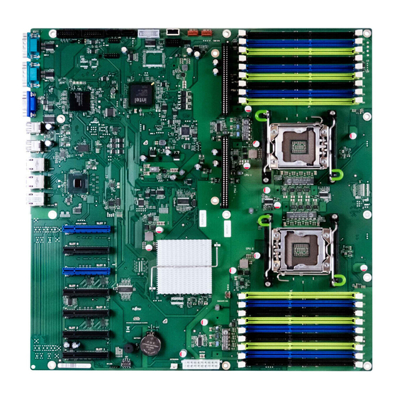
Page 29: Interfaces And Connectors
Features Interfaces and connectors Interfaces and connectors 12 13 15 16 17 18 Figure 8: Schematic view of the system board D2619 intrusion detection 14 slot for TPM module memory slots for CPU 2 15 SATA1 PCIe slots 16 SATA2... - Page 30 20 USB internal 1 USB 3/4 21 USB internal 2 22 power supply 2 serial 1 23 power supply1 serial 2 24 memory slots for CPU 1 front VGA 25 power supply for fans and HDDs front panel Technical Manual D2619 (RX/TX300 S5)
-
Page 31: External Ports
Features Interfaces and connectors 3.7.1 External ports Figure 9: External ports of the system board D2619 Identification LED (blue) VGA port CSS LED (yellow) USB- port Global Error LED (red) service LAN port serial interface 2 system LAN port 2... - Page 32 Figure 11: LAN connector service LAN controller 1 LAN transfer rate green LAN transfer rate 10 Mbit/s green LAN transfer rate 100 Mbit/s 2 LAN link/activity green LAN connection no LAN connection flashing LAN transfer Technical Manual D2619 (RX/TX300 S5)
-
Page 33: Settings With Switches And Jumpers
BIOS Setup (in Security menu, the Password on boot field must be set to Enabled). The password query is skipped. Passwords are deleted. The password query is effective (default setting). Technical Manual D2619 (RX/TX300 S5) - Page 34 Figure 13: Position of the TPM jumper (TPM enable) Signal Description TPM RESET L Reset of the TPM module ICH TMP DIS L Reset of ICH10 As default the jumper (1-2) is set. Without jumper the TPM function is disabled. Technical Manual D2619 (RX/TX300 S5)
-
Page 35: Replacing The Lithium Battery
Ê Press the locking spring into direction of the arrow (1), so that the lithium battery jumps out of its socket. Ê Remove the battery (2). Ê Insert a new lithium battery of the same type into the socket (3) and (4). Technical Manual D2619 (RX/TX300 S5)