Hitachi SB 8V2 Technical Data And Service Manual
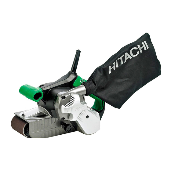
76 mm (3") belt sander
Hide thumbs
Also See for SB 8V2:
- Handling instructions manual (101 pages) ,
- Safety instructions and instruction manual (36 pages) ,
- Handling instructions manual (53 pages)

Related Manuals for Hitachi SB 8V2


Summary of Contents for Hitachi SB 8V2
- Page 1 MODELS SB 8V2 Hitachi Power Tools 76 mm (3”) BELT SANDER TECHNICAL DATA SB 8V2 SERVICE MANUAL LIST No: 0361 Mar. 2007 SPECIFICATIONS AND PARTS ARE SUBJECT TO CHANGE FOR IMPROVEMENT...
- Page 2 REMARK: Throughout this TECHNICAL DATA AND SERVICE MANUAL, a symbol(s) is(are) used in the place of company name(s) and model name(s) of our competitor(s). The symbol(s) utilized here is(are) as follows: Competitor Symbols Utilized Company Name Model Name MAKITA 9903 DEWALT DW433...
-
Page 3: Table Of Contents
9-2. Reassembly ............................ 11 9-3. Wiring Procedures .......................... 12 9-4. Wiring Diagram ..........................12 9-5. Tightening Torque ...........................13 9-6. Insulation Test ..........................13 9-7. No-load Current Value ........................13 10. STANDARD REPAIR TIME (UNIT) SCHEDULES ..............14 Assembly Diagram for SB 8V2... -
Page 4: Product Name
Hitachi 76 mm (3") Belt Sander, Model SB 8V2 2. MARKETING OBJECTIVE The new Model SB 8V2 is the upgraded version of the current Model SB 75. The key features of the Model SB 8V2 are as follows: (1) 1,020 W powerful motor (120 V: 9.0 A) -
Page 5: Selling Point Descriptions
4-1. Selling Point Descriptions (1) Soft grip handles The handle and the sub handle have a soft grip each. The Model SB 8V2 is easier to operate than the conventional model and competitors. (2) Clear cover The Model SB 8V2 is equipped with a clear cover at the top of the body. -
Page 6: Specifications
5. SPECIFICATIONS Model SB 8V2 Capacity 76 mm (3") Power source AC single phase 50 or 60 Hz Type of motor Single-phase series commutator motor Voltage (V) Current Voltage and current Power input 1,020 W 250 to 450 m/min. (820 to 1,475 ft/min.) -
Page 7: Specification Comparisons With Similar Products
6. SPECIFICATION COMPARISONS WITH SIMILAR PRODUCTS HITACHI SB 8V2 SB 75 76 x 533 76 x 533 76 x 533 76 x 533 Belt size (mm) (3" x 21") (3" x 21") (3" x 21") (3" x 21") Speed Variable speed... -
Page 8: Precautions In Sales Promotion
7. PRECAUTIONS IN SALES PROMOTION In the interest of promoting the safest and most efficient use of the Model SB 8V2 Belt Sander by all of our customers, it is very important that at the time of sale the salesperson carefully ensures that the buyer seriously recognizes the importance of the contents of the Handling Instructions, and fully understands the meaning of the precautions listed on the caution plate attached to each tool. -
Page 9: Dust Collection
8. DUST COLLECTION 8.1 Dust Collector This is a system in which the housing is provided with a dust fan on its side so that air pressure from the dust fan causes grinding dust to be drawn in from the inlet and collected in a dust bag. 8.2 To Maintain Dust Collecting Performance When moist dust is drawn in, the dust collecting section becomes clogged and impairs dust-collecting performance. -
Page 10: Precautions In Disassembly And Reassembly
The [Bold] numbers in the descriptions below correspond to the item numbers in the Parts List and the exploded assembly diagram for the Model SB 8V2. CAUTION: Be sure that the plug is disconnected from the power source during disassembly, reassembly and sanding belt replacement. - Page 11 (e) Remove the Retaining Ring for D10 Shaft [59] before removing the Gear [60]. (f) Remove the Feather Key 3 x 3 x 8 [64] and Washer (B) D19 [43] before removing the Drive Pulley [65]. (g) Loosen the four Tapping Screws (W/Flange) D5 x 45 [15] before removing the Dust Cover [16] from the Housing Ass'y [21].
- Page 12 (3) Removal of the Housing Ass'y [21] and the Body Ass'y [45] (Fig. 3) (a) Loosen two Machine Screws M4 x 10 [47] and remove the Shoe Plate [63] and the Shoe Cushion [62]. (b) Put a Phillips-head screwdriver through a hole of the Body Ass'y [45] and loosen the Tapping Screw (W/Flange) D4 x 16 (Black) [28].
- Page 13 (5) Removal of the Stator Ass'y [7] (Fig. 5) (a) Loosen the three Tapping Screws (W/Flange) D4 x 16 (Black) [28] and remove the Handle Cover [17]. (b) Loosen the Machine Screws (W/Washer) M3.5 x 6 [32] which tighten the lead wires from the Stator Ass'y [7] to Switch (E) (1P Screw Type) W/Lock [29].
-
Page 14: Reassembly
9-2. Reassembly Reassembly can be accomplished by following the disassembly procedures in reverse. However, special attention should be given to the following items. (a) Fill the gear cover with Shell Alvania RL3 Grease. (b) Impregnate the felt on the body and the idle pulley with 1.5 cc of Turbine Oil No. 90. (c) When tightening the Tapping Screw (W/Flange) D5 x 45 [15] through the Dust Cover [16] into the Housing Ass'y [21] (Fig. -
Page 15: Wiring Procedures
9-3. Wiring Procedures Be careful not to crush the lead wires by putting them between the housing and the handle cover. Switch (E) (1P Screw Type) W/Lock [29] Connector 50091 [30] Controller [34] Fig. 8 9-4. Wiring Diagram Wiring should be done in accordance with Fig. 9. Fig. -
Page 16: Tightening Torque
9-5. Tightening Torque Tapping Screw (W/Flange) D4 x 16 ..............2.0 0.5 N m (20 5 kgf • • Tapping Screw (W/Flange) D4 x 30 ..............2.0 0.5 N m (20 5 kgf • • Tapping Screw (W/Flange) D5 x 45 ..............2.9 0.5 N m (30 5 kgf... -
Page 17: Standard Repair Time (Unit) Schedules
10. STANDARD REPAIR TIME (UNIT) SCHEDULES Variable 60 min. MODEL Fixed Work Flow SB 8V2 Body Ass'y General Assembly Belt Dust Cover Handle Cover Housing Ass'y Pulley (B) Clear Cover Switch (E) Armature Ass'y Belt Cover Shoe Cushion Controller Ball Bearing... - Page 18 Hitachi Power Tools LIST NO. 0361 ELECTRIC TOOL PARTS LIST BELT SANDER 2007 • • Model SB 8V2 (E1)
- Page 19 PARTS SB 8V2 ITEM CODE NO. DESCRIPTION REMARKS USED 327-742 PULLEY (A) 600-0VV BALL BEARING 6000VVCMPS2L 327-739 DUST GUIDE 360-797C ARMATURE 110V 360-797U ARMATURE ASS’Y 120V INCLUD. 2, 5 360-797E ARMATURE 220V-230V 360-797F ARMATURE 240V 608-VVM BALL BEARING 608VVC2PS2L 953-174 HEX.
- Page 20 PARTS SB 8V2 ITEM CODE NO. REMARKS DESCRIPTION USED 959-140 CONNECTOR 50091 (10 PCS.) 328-432 VARISTOR FOR GBR, EUROPE, FIN, NOR, SWE, DEN, AUT 305-499 MACHINE SCREW (W/WASHER) M3.5X6 980-063 TERMINAL 327-753 CONTROLLER 100V-110V 327-757 CONTROLLER 120V 327-758 CONTROLLER 220V-240V...
-
Page 21: Optional Accessories
STANDARD ACCESSORIES SB 8V2 ITEM CODE NO. DESCRIPTION REMARKS USED 323-011 DUST BAG (BLACK) OPTIONAL ACCESSORIES ITEM CODE NO. DESCRIPTION REMARKS USED 939-736 SANDING BELTS 76X533 WA150 (10 PCS.) 939-737 SANDING BELTS 76X533 WA180 (10 PCS.) 939-738 SANDING BELTS 76X533 WA240 (10 PCS.) 939-739 SANDING BELTS 76X533 AA30 (10 PCS.)