Hitachi C 12LCH Technical Data And Service Manual
Compound miter saw
Hide thumbs
Also See for C 12LCH:
- Handling instructions manual (100 pages) ,
- Safety instructions and instruction manual (84 pages) ,
- User manual (23 pages)
Table of Contents
Advertisement
Quick Links
Advertisement
Table of Contents

Related Manuals for Hitachi C 12LCH


Summary of Contents for Hitachi C 12LCH
- Page 1 Hitachi Power Tools COMPOUND MITER SAW TECHNICAL DATA C 12LCH C 12LC SERVICE MANUAL C 12FCH LIST Nos. C 12LCH: E938 Revised June 2005 C 12LC : E940 C 12FCH: E939 SPECIFICATIONS AND PARTS ARE SUBJECT TO CHANGE FOR IMPROVEMENT...
- Page 2 REMARK: Throughout this TECHNICAL DATA AND SERVICE MANUAL, a symbol(s) is(are) used in the place of company name(s) and model name(s) of our competitor(s). The symbol(s) utilized here is(are) as follows: Competitor Symbol Utilized Company Name Model Name DW705S DEWALT 36-255L DELTA RIDGID...
-
Page 3: Table Of Contents
7-3. Relative Standards ......................... 10 7-4. Laser Marker (Models C 12LCH/C 12FCH) ..................10 7-5. Ambient Illuminance and Visibility of Laser Line (Models C 12LCH/C 12FCH) ......11 8. ADJUSTMENT AND OPERATION PRECAUTIONS ..............12 8-1. Position Adjustment of Laser Line (Models C 12LCH/C 12FCH) ............ 12 8-2. - Page 4 Page 11-9. Adjustment of Laser Marker Accuracy (Models C 12LCH/C 12FCH) ..........43 11-10. Tightening Torque ........................46 12. REPAIR GUIDE ........................... 47 13. STANDARD REPAIR TIME (UNIT) SCHEDULES ..............52 Assembly Diagram for C 12LCH Assembly Diagram for C 12LC...
-
Page 5: Product Name
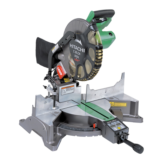
Following the 10" compound miter saw Model C 10FCH equipped with the laser marker, we introduce the new three 12" compound miter saws Models C 12LCH, C 12LC and C 12FCH. The Models C 12LCH and C 12LC are equipped with the class-first digital display panel that indicates miter/bevel angles. With the new Models C 12LCH, C 12LC and C 12FCH, we aim to expand our market share. -
Page 6: Selling Point Descriptions
(3) Bevel angle fine adjustment The Models C 12LCH, C 12LC and C 12FCH are easily and finely adjustable to an optional bevel angle. Pulling the plates allows the bevel angle to be adjusted by about 48û to the left or about 3û to the right with one-touch simple operation. - Page 7 (7) Powerful 15 amps motor (for the U.S.A. and Canada) The Models C 12LCH, C 12LC and C 12FCH are equipped with a 15-ampere motor. The Models C 12LCH, C 12LC and C 12FCH can cut workpieces as quickly as the Model C 10FCB.
-
Page 8: Specifications
Not provided Not provided Not provided Digital display Precision 0.5û (It is not the actual precision when cutting a wood workpiece.) (For Models C 12LCH/C 12LC) Laser marker < 1 mW (CLASS II ) Maximum output (Models Wave length 400 nm --- 700 nm... - Page 9 • • • • • • • • • • • • • • • Dust bag Vise ass'y 17 mm box wrench 4 mm hex. bar wrench (For Models C 12LCH/C 12FCH) 305 mm (12") TCT saw blade (60 teeth, Code No. 305546) Optional accessories Extension holder and stopper...
-
Page 10: Comparisons With Similar Products
6. COMPARISONS WITH SIMILAR PRODUCTS Maker/Model HITACHI Item C 12LCH/C 12LC/C 12FCH 63.5 mm x 200 mm 57 mm x 203 mm 51 mm x 203 mm 63.5 mm x 200 mm (2-1/2" x 7-7/8") (2-1/4" x 8") (2" x 8") (2-1/2"... -
Page 11: Precautions In Sales Promotion
7. PRECAUTIONS IN SALES PROMOTION In the interest of promoting the safest and most efficient use of the Models C 12LCH, C 12LC and C 12FCH Compound Miter Saws by all of our customers, it is very important that at the time of sale the salesperson... - Page 12 Warning label (A) specified by the UL is affixed on the right side of the base. Please instruct users to strictly observe the contents 1 to 9 in warning label (A) shown above. (3) Caution label (B) (at the side of the gear case) (Models C 12LCH/C 12FCH) Fig. 4...
- Page 13 Caution labels (C) and (D) (at the front of the base) (Models C 12LCH/C 12FCH) USA/CAN Fig. 6-1 Fig. 6-2 (5) Warning label (C) (at the front of sub fence) Fig. 7 (6) Caution label (F) (at the front of link (B)) (for Europe) Fig.
-
Page 14: Relative Standards
7-4. Laser Marker (Models C 12LCH/C 12FCH) The Models C 12LCH and C 12FCH are equipped with the laser marker that complies with the U. S. A. standard, FDA Complies with 21 CFR, Food and Drugs, Part 1040 "Performance Standard for Light-emitting Products", Class II. -
Page 15: Ambient Illuminance And Visibility Of Laser Line (Models C 12Lch/C 12Fch)
7-5. Ambient Illuminance and Visibility of Laser Line (Models C 12LCH/C 12FCH) The visibility of the laser line on the workpiece changes depending on the brightness of the working environment. Instruct the customer to consider the brightness of the working environment when using the laser marker referring to the following table. -
Page 16: Adjustment And Operation Precautions
8. ADJUSTMENT AND OPERATION PRECAUTIONS 8-1. Position Adjustment of Laser Line (Models C 12LCH/C 12FCH) The laser line is adjusted to the width of the saw blade at the time Saw blade Workpiece of factory shipment. Depending upon the cutting choice, align the laser line with the left side of the cutting width (saw blade) or the right side according to the following procedure. - Page 17 The laser marker will not light up if the digital display switch is turned off. (Only Model C 12LCH) Instruct the above precautions on the laser marker to the customers.
-
Page 18: How To Use The Vise Assembly
8-2. How to Use the Vise Assembly Screw holder 6 mm wing Knob (1) The vise assembly can be mounted on either the left bolt (B) fence (fence (B)) or the right fence (fence (A)) by Vise plate loosening 6 mm wing bolt (A). (2) The screw holder can be raised or lowered according to Fence the height of the workpiece by loosening 6 mm wing bolt... -
Page 19: Cutting Operation
(4) Press cutting The Models C 12LCH, C 12LC and C 12FCH can be used for press cutting of workpieces up to 63.5 mm x 200 mm (2-1/2" x 7-7/8") (except for Europe) in a single operation by simply pushing the saw blade section (head) downward. - Page 20 (7) Bevel angle fine adjustment Handle Knob (A) 8 mm bolt (A) Clamp lever Knob (A) Plate (A) 8 mm bolt (B) Plate (B) Fig. 15-2 Fig. 15-1 Grip the handle on the motor head and position it at the bevel angle you need. Temporarily tighten the clamp lever.
- Page 21 (8) Compound (miter + bevel) cutting Compound cutting can be accomplished by combining the miter cutting and bevel cutting operations described in paragraphs (5) and (6) above. (For details, please refer to the Instruction Manual.) When the saw blade section (head) is inclined 45û to the left, the table can be turned up to 45û to the right and left. (9) Crown molding cutting This machine can cut two types of crown molding workpieces by combining the miter and bevel cutting operations (for USA).
- Page 22 (1) Setting to cut crown molding at positions in Fig. 17 (See Fig. 18, tilt the head to the left.): Turn the turn table to the right and set the miter angle as follows: For 45û type crown moldings: 35.3û ( mark) For 38û...
- Page 23 Cutting method of crown molding without tilting the saw blade (1) Crown molding stoppers (L) and (R) (optional accessories) allow easier cuts of crown molding without tilting the saw blade. Install them to both sides of the base as shown in Fig. 22. After inserting, tighten the 6 mm knob bolts to secure the crown molding guides.
-
Page 24: Digital Display Panel (Models C 12Lch/C 12Lc)
The laser marker will not light up if the digital display switch is turned off. (only Model C 12LCH) Do not use the main unit near equipment that generates electrical noise such as generators. - Page 25 CAUTION: If the figure shown on the miter angle digital display is different from the positive stop angle (for example, 45.0û 45.5û, 31.6û 32.0û) then the positive stop has probably deviated slightly from its correct position. If this happens, do as follows. (1) Move the turn table left and right with the side handle loosened, and set the turn table to the correct position.
-
Page 26: Adjustment Of Components
9. ADJUSTMENT OF COMPONENTS 9-1. Bevel Angle Adjustment Before the power tool is shipped from the factory, it is adjusted for 0û, left 45û bevel cutting angle with the 8 mm nylock bolt. When changing the adjustment, change the height of the 8 mm nylock bolt by turning them. (The maximum bevel cutting angle is 48û). - Page 27 Packing (B) Packing (E) Packing (C) Fig. 29 Fig. 28 Upper packing Carton box Packing (A) Base packing Fig. 30 --- 23 ---...
-
Page 28: Precautions In Disassembly And Reassembly
[Bold] numbers in the descriptions below correspond to the item numbers in the pars list and exploded assembly diagram of the Model C 12LCH. For the Models C 12LC and C 12FCH, refer to the parts list separately. Be sure to first disconnect the power plug when performing disassembly or replacement of the saw blade. - Page 29 Fig. 32 1. Remove the Machine Screw (W/Washers) M4 x 10 (Black) [68] and Indicator (B) [67]. Remove the two Machine Screws (W/Washers) M5 x 16 [46] and remove the Dust Guide Ass'y [45]. 2. Remove the Nylon Nut M6 [143] with a wrench 10 mm and remove the Flat Hd. Screw M6 x 30 [153] and the Sub Fence Ass'y [146].
- Page 30 7. Remove the Machine Screw (W/Washers) M4 x 16 [31] and the Nylon Clip [32]. Then remove the four Machine Screws M4 x 10 [38] to remove the Hinge Cover [33]. Press the Encoder [37] turning clockwise and secure it with the Machine Screw M5 x 20 [34]. NOTE: When reassembling the Hinge [30A] to the Turn Table [107], loosen the Machine Screw M5 x 20 [34] securing the Encoder [37] (about one turn) and move the Encoder [37] to engage with Gear (B) [72].
- Page 31 B. Armature ass'y Cord, stator ass'y and housing ass'y Tools required: • Phillips screwdriver • Flat-blade screwdriver • Plastic hammer • Nippers Fig. 33 --- 27 ---...
- Page 32 D4 x 20 (Black) [246], then remove Switch Handle (C) [247]. 2. Remove the three connectors of Cord (B) [238] (Model C 12LCH only) (Model C 12LC: one connector of Cord (C) Model C 12FCH: one connector of internal wire of Laser Module (A) Ass'y [12A]) and disconnect the two Connectors 50092 [243] crimping the internal wire.
- Page 33 C. Safety cover and link Spindle and spring Tools required: • Phillips screwdriver • Hex. bar wrench 5 mm • Hex. bar wrench 4 mm • Hex. bar wrench 2.5 mm • Box wrench 17 mm (standard accessory) • Plastic hammer •...
- Page 34 1. Remove the Machine Screw M5 x 10 (Black) [234] at the notched side of the Spindle Cover [236] and slide the Spindle Cover [236] to remove the TCT Saw Blade 305 mm-D25.4 Hole-NT32 [193] in the next step. 2. Remove Bolt (A) M10 [191] using the box wrench 17 mm (standard accessory). Then Washer (B) [192], TCT Saw Blade 305 mm-D25.4 Hole-NT32 [193] and the other Washer (A) [194] can be removed in this order.
- Page 35 D4 x 20 (Black) [246], then remove Switch Handle (C) [247]. Remove the wire of the Laser Module (A) Ass'y [12A] from Cord (B) [238]. (Only the Model C 12LCH) 2. Remove the two Machine Screws (W/Washers) M4 x 16 [209] and the Gear Case Cover Ass'y [210].
- Page 36 F. Digital display (Models C 12LCH/C 12LC) Tool required: • Phillips screwdriver Fig. 37 1. Remove the Indication Panel Ass'y [128] and Packing (D) [129] and remove the four Machine Screws (W/ Washers) M4 x 16 [126]. 2. Remove the two Machine Screws (W/Washers) M5 x 16 [124] securing Table Insert (A) [122] and remove Table Insert (A) [122].
-
Page 37: Reassembly
(4) When replacing the Return Spring [223], apply 2 grams of Hitachi Motor Grease to the inner circumference of the new Return Spring [223] prior to reassembly. (5) When replacing Liner (B) [56], apply 5 grams of Hitachi Motor Grease to the sliding surface of the Turn Table [107] prior to reassembly. -
Page 38: Wiring Diagram
Laser Module (A) Ass'y [12A] and the Switching Power Supply [249]. Do not stare into beam while the laser marker is lighting. Wiring diagram (C 12LCH) USA/CAN Fig. 38-1 --- 34 ---... - Page 39 Wiring diagram (C 12LCH) Fig. 38-2 --- 35 ---...
- Page 40 C 12LCH Europe/AUS/NZL/China Fig. 39-1 Fig. 39-2 --- 36 ---...
- Page 41 Wiring diagram (C 12LC) USA/CAN Fig. 40-1 Fig. 40-2 --- 37 ---...
- Page 42 C 12LC Europe/NZL Fig. 41-1 Fig. 41-2 --- 38 ---...
- Page 43 Wiring diagram (C 12FCH) USA/CAN Fig. 42-1 Fig. 42-2 --- 39 ---...
- Page 44 C 12FCH Europe/NZL/Asia Fig. 43-1 Fig. 43-2 --- 40 ---...
-
Page 45: No-Load Current
Base Ass'y [169], tighten the Nylon Nut M8 [118] so that the Turn Table [107] turns smoothly without excessive play or vibration. During reassembly, liberally apply grease (Hitachi Motor Grease) at the point marked "A" in Fig. 45. Fig. 45... -
Page 46: Lubrication
11-7. Lubrication Advise the customer to lubricate the machine as indicated below at least once a month. Also, prior to applying lubrication, any sawdust, dirt or other foreign matter should be thoroughly wiped away with a soft cloth. (1) Swiveling section of the Gear Case [208] and the Hinge [30A] Coat the swiveling and sliding portion of the Gear Case [208] and the Hinge [30A] with machine oil. -
Page 47: Adjustment Of Laser Marker Accuracy (Models C 12Lch/C 12Fch)
11-9. Adjustment of Laser Marker Accuracy (Models C 12LCH/C 12FCH) (1) Construction of laser marker and functions of each component Fig. 47 CAUTION: Exercise utmost caution in handling a switch trigger for the position adjustment of the laser line, as the power plug is plugged into the receptacle during operation. If the switch trigger is pulled inadvertently, the saw blade can rotate and result in unexpected accidents. - Page 48 (2) Adjustment of squareness with the fence surface The laser line inclines to the left by turning the Hex. Socket Set Screw M5 x 6 [6] clockwise and inclines to the right by turning counterclockwise. The squareness of the laser line with the fence surface can be adjusted in this manner.
- Page 49 (4) Adjustment of the laser marker Adjust the laser marker according to the following steps from Adjust the product accuracy first because the accuracy of the laser marker is adjusted aligning the cut surface of the workpiece. First, hold a workpiece of 38 mm in height and 89 mm in width with the vise and perform right-angle cutting.
-
Page 50: Tightening Torque
11-10. Tightening Torque (1) Model: C 12LCH • Machine Screw (W/Washers) M6 x 20 (Black) [16] 43.4 in-lbs. (4.9 N m, 50 kgf • • • Machine Screw M5 x 20 [34] [112] 26 in-lbs. (2.9 N m, 30 kgf •... -
Page 51: Repair Guide
12. REPAIR GUIDE Unit: mm Factory Inspection, repair or Item Phenomenon Cause standard adjustment • Adjust squareness with the a Inaccurate 0.2/100 Inaccurate cutting Nylock Bolt M8 x 25 [65]. squareness between (Dummy disc) Inaccurate • • • the turn table and the (Fig. - Page 52 • Replace the saw blade. is applied due to dull saw blade. d Incorrect saw blade is ------ • Use a suitable Hitachi-supplied used. saw blade. • If the saw blade has a large number of teeth, the cutting resistance will be increased.
- Page 53 3,600 --- 4,400 min voltage. appropriate. Laser marker does not a Improper wiring ------ • Check the wiring. light. (Models C 12LCH/ C 12FCH) b Switch (B) failure ------ • Check Switch (B) (1P Type) (Only Model C 12LCH) [253] for conductivity.
- Page 54 Laser line does not a Ink line is not right ------ • Make a correct ink line again. match the ink line. angle. (Models C 12LCH/ C 12FCH) b Laser marker accuracy 0.2/100 • Readjust the accuracy of the is not adjusted (Figs.
- Page 55 Digital display does not a Same as item 10- a • Same as item 10- a to f . indicate properly. to f . (Models C 12LCH/ C 12LC) b Encoder failure • Replace the Encoder [109]. (Miter angle) • Replace the Encoder [109].
-
Page 56: Standard Repair Time (Unit) Schedules
13. STANDARD REPAIR TIME (UNIT) SCHEDULES Variable 70 min. MODEL Fixed Work Flow C 12LCH C 12LC General Assembly C 12FCH Switching Switch Handle Switch Lever (A) Power Supply Switch (A) Switch (B) [C 12LCH] Switch Switch Handle (D) Ass'y... - Page 57 Hitachi Power Tools LIST NO. E938 ELECTRIC TOOL PARTS LIST COMPOUND SAW 2005 • • Model C 12LCH (E2)
- Page 58 C 12LCH 123 124 143 144 159A 171 172 618 619 601 621 --- 2 --- 6 -- 05...
- Page 59 C 12LCH 213 216 6 -- 05 --- 3 -- -...
- Page 60 PARTS C 12LCH ITEM CODE NO. DESCRIPTION REMARKS USED 323-141 SPRING (B) 323-137 LASER HOLDER (A) 323-138 LASER HOLDER (B) 949-900 ROLL PIN D3X14 (10 PCS.) 323-142 SPRING (C) 962-782 HEX. SOCKET SET SCREW M5X6 949-531 SPLIT PIN D2X12 (10 PCS.)
- Page 61 PARTS C 12LCH ITEM CODE NO. REMARKS DESCRIPTION USED 949-821 HEX. SOCKET HD. BOLT M5X16 (10 PCS.) 323-664 GEAR (C) ASS’Y 1 INCLUD. 54 949-900 ROLL PIN D3X14 (10 PCS.) 949-660 HEX. SOCKET HD. BOLT M6X20 (10 PCS.) 323-683 LINER (B) 949-221 MACHINE SCREW M4X20 (10 PCS.)
- Page 62 PARTS C 12LCH ITEM CODE NO. DESCRIPTION REMARKS USED 990-541 MACHINE SCREW (W/WASHERS) M5X16 323-612 MONITOR (A) 993-539 MACHINE SCREW (W/WASHERS) M4X16 323-616 PANEL SHEET (A) 323-615 INDICATION PANEL ASS’Y INCLUD. 127 323-608 PACKING (D) 321-672 TAPPING SCREW D2X6 323-613...
- Page 63 PARTS C 12LCH ITEM CODE NO. REMARKS DESCRIPTION USED 323-610 MONITOR ASS’Y INCLUD. 125, 130-133 988-101 BOLT (A) M10 323-652 WASHER (B) EXCEPT FOR EUROPE 323-522 TCT SAW BLADE 305MM-D25.4 HOLE-NT32 324-268 TCT SAW BLADE 305MM-D30 HOLE-NT32 324-269 TCT SAW BLADE 305MM-D25.4 HOLE-NT120 1...
- Page 64 PARTS C 12LCH ITEM CODE NO. DESCRIPTION REMARKS USED 500-234Z CORD (CORD ARMOR D10.7) 500-435Z CORD (CORD ARMOR D10.7) FOR GBR (230V) 500-461Z CORD (CORD ARMOR D10.7) FOR GBR (110V) 500-247Z CORD (CORD ARMOR D10.7) FOR FIN 500-453Z CORD (CORD ARMOR D10.7) FOR USA, CAN...
- Page 65 PARTS C 12LCH ITEM CODE NO. REMARKS DESCRIPTION USED 322-123 MACHINE SCREW (W/WASHERS) M5X40 (BLACK) 324-625 LEVER SPRING (A) FOR EUROPE 323-990 LEVER SHAFT FOR EUROPE 324-626 LOCK LEVER (D) FOR EUROPE 877-371 NYLON NUT M5 FOR EUROPE 949-236 MACHINE SCREW M5X10 (10 PCS.)
-
Page 66: Standard Accessories
STANDARD ACCESSORIES C 12LCH ITEM CODE NO. DESCRIPTION REMARKS USED 944-458 HEX. BAR WRENCH 4MM 985-051 BOX WRENCH 17MM 322-955 DUST BAG OPTIONAL ACCESSORIES ITEM CODE NO. DESCRIPTION REMARKS USED 323-546 CROWN MOLDING STOPPER (L) ASS’Y INCLUD. 602-605 301-806 WING BOLT M6X15... - Page 67 Hitachi Power Tools LIST NO. E940 ELECTRIC TOOL PARTS LIST COMPOUND SAW 2005 • • Model C 12LC (E2)
- Page 68 C 12LC 123 124 143 144 159A 618 619 601 621 --- 2 --- 6 -- 05...
- Page 69 C 12LC 213 216 6 -- 05 --- 3 -- -...
- Page 70 PARTS C 12LC ITEM CODE NO. DESCRIPTION REMARKS USED 323-208 MACHINE SCREW (W/WASHERS) M6X20 (BLACK) 322-935 CLAMP LEVER 323-665 BOLT (LEFT HAND) M10 323-666 KNOB (A) 323-597 GEAR BOX (C) 304-043 MACHINE SCREW (W/WASHERS) M4X10 (BLACK) 323-598 GEAR BOX (C) COVER 323-599 PINION 949-821...
- Page 71 PARTS C 12LC ITEM CODE NO. REMARKS DESCRIPTION USED 304-043 MACHINE SCREW (W/WASHERS) M4X10 (BLACK) 680-418 NYLON NUT M12 951-039 MACHINE SCREW (W/SP. WASHER) M4X12 949-423 WASHER M4 (10 PCS.) 323-607 GEAR (B) 323-627 SPRING PLATE 949-457 SPRING WASHER M8 (10 PCS.) 949-655 HEX.
- Page 72 PARTS C 12LC ITEM CODE NO. DESCRIPTION REMARKS USED 949-216 MACHINE SCREW M4X10 (10 PCS.) 322-954 VISE SHAFT 311-144 NYLON NUT M6 304-043 MACHINE SCREW (W/WASHERS) M4X10 (BLACK) 323-631 PLATE (C) 323-630 SUB FENCE ASS’Y INCLUD. 147 WARNING LABEL (H) 301-806 WING BOLT M6X15 949-678...
- Page 73 PARTS C 12LC ITEM CODE NO. REMARKS DESCRIPTION USED 993-539 MACHINE SCREW (W/WASHERS) M4X16 323-689 GEAR CASE COVER 322-948 WASHER M7 323-674 LINK EXCEPT FOR EUROPE 322-950 SPECIAL SCREW M6 322-950 SPECIAL SCREW M6 FOR EUROPE 318-363 FLAT HD. SCREW M4X10 (BLACK) 323-691 PROTECTIVE COVER (B) 949-454...
- Page 74 PARTS C 12LC ITEM CODE NO. DESCRIPTION REMARKS USED 323-633 INTERNAL WIRE (A) FOR USA, CAN 322-914 HOUSING ASS’Y INCLUD. 260, 261 938-477 HEX. SOCKET SET SCREW M5X8 938-241 BRUSH HOLDER 999-038 CARBON BRUSH (1 PAIR) FOR 110V-120V 999-065 CARBON BRUSH (1 PAIR) FOR 220V-240V 945-161 BRUSH CAP...
- Page 75 STANDARD ACCESSORIES C 12LC ITEM CODE NO. DESCRIPTION REMARKS USED 985-051 BOX WRENCH 17MM 322-955 DUST BAG OPTIONAL ACCESSORIES ITEM CODE NO. DESCRIPTION REMARKS USED 323-546 CROWN MOLDING STOPPER (L) ASS’Y INCLUD. 602-605 301-806 WING BOLT M6X15 CROWN MOLDING STOPPER (L) 321-390 CROWN MOLDING STOPPER HOLDER 323-682...
- Page 76 C 12LC ITEM CODE NO. DESCRIPTION REMARKS USED --- 10 --- Printed in Japan 6 -- 05 (050630N)
- Page 77 Hitachi Power Tools LIST NO. E939 ELECTRIC TOOL PARTS LIST COMPOUND SAW 2005 • • Model C 12FCH (E2)
- Page 78 C 12FCH 123 124 118 119 143 144 159A 171 172 618 619 601 621 --- 2 --- 6 -- 05...
- Page 79 C 12FCH 213 216 6 -- 05 --- 3 -- -...
- Page 80 PARTS C 12FCH ITEM CODE NO. DESCRIPTION REMARKS USED 323-141 SPRING (B) 323-137 LASER HOLDER (A) 323-138 LASER HOLDER (B) 949-900 ROLL PIN D3X14 (10 PCS.) 323-142 SPRING (C) 962-782 HEX. SOCKET SET SCREW M5X6 949-531 SPLIT PIN D2X12 (10 PCS.) 323-144 SPECIAL BOLT M5 975-144...
- Page 81 PARTS C 12FCH ITEM CODE NO. REMARKS DESCRIPTION USED 303-006 SPACER D4X10 949-432 BOLT WASHER M6 (10 PCS.) 323-662 BEVEL PLATE (B) 323-661 BEVEL PLATE (A) 323-659 COVER (A) 303-409 NYLOCK BOLT M8X25 935-196 MACHINE SCREW (W/WASHERS) M4X12 (BLACK) 322-893 INDICATOR (B) 304-043 MACHINE SCREW (W/WASHERS) M4X10 (BLACK)
- Page 82 PARTS C 12FCH ITEM CODE NO. DESCRIPTION REMARKS USED 949-610 BOLT M6X10 (10 PCS.) 987-512 MACHINE SCREW (W/SP. WASHER) M5X16 323-605 HOOK 323-628 FENCE (A) 949-510 RIVET D2.5X4.8 (10 PCS.) FOR USA, CAN WARNING LABEL (A) FOR USA, CAN 323-606 BASE RUBBER 324-651 BASE ASS’Y...
- Page 83 PARTS C 12FCH ITEM CODE NO. REMARKS DESCRIPTION USED 322-926 LASER COVER (A) 322-947 SPECIAL SCREW (C) M5 322-938 WASHER M10 949-215 MACHINE SCREW M4X8 (10 PCS.) 323-040 MACHINE SCREW M5X10 (BLACK) 323-040 MACHINE SCREW M5X10 (BLACK) FOR EUROPE, USA, CAN, AUS 949-431 BOLT WASHER M5 (10 PCS.) FOR EUROPE, USA, CAN, AUS...
- Page 84 PARTS C 12FCH ITEM CODE NO. DESCRIPTION REMARKS USED 323-637 LOCK LEVER 302-428 WASHER (A) 600-0VV BALL BEARING 6000VVCMPS2L 322-915 FAN GUIDE 953-174 HEX. HD. TAPPING SCREW D5X55 340-603D STATOR ASS’Y 110V INCLUD. 274 340-603C STATOR ASS’Y 120V INCLUD. 274 340-603E STATOR ASS’Y 220V INCLUD.
- Page 85 STANDARD ACCESSORIES C 12FCH ITEM CODE NO. DESCRIPTION REMARKS USED 944-458 HEX. BAR WRENCH 4MM 985-051 BOX WRENCH 17MM 322-955 DUST BAG OPTIONAL ACCESSORIES ITEM CODE NO. DESCRIPTION REMARKS USED 323-546 CROWN MOLDING STOPPER (L) ASS’Y INCLUD. 602-605 301-806 WING BOLT M6X15 CROWN MOLDING STOPPER (L) 321-390 CROWN MOLDING STOPPER HOLDER...
- Page 86 C 12FCH ITEM CODE NO. DESCRIPTION REMARKS USED --- 10 --- Printed in Japan 6 -- 05 (050630N)