Sign In
Upload
Manuals
Brands
Mitsubishi Electric Manuals
Controller
FX3S-30MR/ES-2AD
Mitsubishi Electric FX3S-30MR/ES-2AD Manuals
Manuals and User Guides for Mitsubishi Electric FX3S-30MR/ES-2AD. We have
2
Mitsubishi Electric FX3S-30MR/ES-2AD manuals available for free PDF download: User Manual, Hardware Manual
Mitsubishi Electric FX3S-30MR/ES-2AD User Manual (216 pages)
Brand:
Mitsubishi Electric
| Category:
Controller
| Size: 5.55 MB
Table of Contents
Safety Precautions
7
Table of Contents
9
Standards
16
Certification of UL, Cul Standards
16
Compliance with EC Directive (CE Marking)
16
Requirement for Compliance with EMC Directive
16
Requirement for Compliance with LVD Directive
17
Caution for Compliance with EC Directive
18
1 Introduction
19
Introduction of Manuals
19
Classification of Major Components in this Manual
19
Manual Organization and Position of this Manual
20
List of Manuals
21
Generic Names and Abbreviations Used in Manuals
24
2 Features and Part Names
25
Major Features
25
Names and Functions of Parts
27
Front Panel
27
Sides
29
3 Introduction of Products
30
List of Products and Interpretation of Model Names
30
Main Units
31
Expansion Boards
32
Connector Conversion Adapter
32
Special Adapters
32
Display Module
32
Memory Cassette
32
Connector Types and Cables for Program Communication
33
Programming Tool
34
Communication Cables
34
Converters and Interface
34
4 Specifications, External Dimensions and Terminal Layout (Main Units)
35
Generic Specifications
35
Dielectric Withstand Voltage Test and Insulation Resistance Test
36
Power Supply Specifications
36
AC Power Type
36
DC Power Type
36
Input Specifications
37
DC Input (Sink/Source)
37
Output Specifications
38
Relay Output Specifications
38
Transistor Output Specifications
39
Performance Specifications
40
External Dimensions (Weight/Accessories/Installation)
42
Main Units
42
Terminal Layout
43
Interpretation of Terminal Block Layout
43
Fx 3S -10M
44
Fx 3S -14M
44
Fx 3S -20M
45
Fx 3S -30M
45
5 Version Information and Peripheral Equipment Connectability
46
Version Information
46
Manufacturer's Serial Number Check Method
46
Version Check Method
47
Version Upgrade History
47
Programming Tool Applicability
47
Applicable Versions of Programming Tool
47
In the Case of Programming Tool (Version) Not Applicable
47
Program Transfer Speed and Programming Tools
48
Cautions on Connecting Peripheral Equipment by Way of Expansion Board or Special Adapter
48
Cautions on Write During RUN
49
Use of (Built-In USB) Programming Port
51
Installation of USB Driver
51
Setting in GX Works2
51
Cautions on Using FA Transparent Function in GOT1000 Series
52
Cautions on Using Transparent Port (2-Port) Function of GOT-F900 Series
53
Other Peripheral Equipment Applicability
54
6 Examination of System Configuration
55
Configuration of a Whole System
55
Expansion Board/Connector Conversion Adapter/Memory Cassette System Configuration
55
Special Adapter System Configuration
56
7 Installation in Enclosure
57
Installation Location
59
Installation Location in Enclosure
59
Space in Enclosure
59
Examination for Installing Method in Enclosure
60
Procedures for Installing on and Detaching from DIN Rail
60
Preparation for Installation
60
Installation of Main Unit
61
Removal of Main Unit
62
Procedures for Installing Directly (with M4 Screws)
63
Hole Pitches for Direct Mounting
63
Example of Mounting Hole Pitches
64
Installation of Main Unit
64
Connecting Methods for Main Unit and Extension Devices
64
Connection of Extension Devices
64
Connecting Method a - Connection of Expansion Board
65
Connecting Method B - Connection of Connector Conversion Adapter
66
Connecting Method C - Connection of Special Adapter
67
Application of Labels
68
Application of Station No. Label (FX 3G -485-BD)
68
Application of Station No. Label (FX 3G -485-BD-RJ)
68
Application of Trimmer Layout Label (FX 3G -8AV-BD)
69
8 Preparation for Wiring and Power Supply Wiring Procedures
70
Preparation for Wiring
72
Wiring Procedures
72
Cable Connecting Procedures
73
Terminal Block [Main Unit]
73
Terminal Block (for European) [Expansion Board and Special Adapters]
74
Grounding Terminal of the FX 3G -485-BD-RJ
75
Grounding Terminal of the FX 3U -ENET-ADP
76
Grounding
77
Examples of External Wiring [AC Power Type]
78
Examples of External Wiring [DC Power Type]
79
9 Input Wiring Procedures
80
Before Starting Input Wiring
82
Sink and Source Input
82
DC Input (Sink and Source Input Type)
83
Handling of 24 V DC Input
83
Instructions for Connecting Input Devices
84
Examples of External Wiring [AC Power Type]
86
Examples of External Wiring [DC Power Type]
87
Input Interruption (I00 to I50)
88
Allocation of Pointers to Input Numbers (Input Signal ON/OFF Duration)
88
Cautions for Input Interruption
88
Examples of External Wiring
89
Pulse Catch (M8170 to M8175)
90
Allocation of Special Memories to Input Numbers (on Duration of Input Signals)
90
Cautions for Pulse Catch
90
Examples of External Wiring
91
10 Use of High-Speed Counters
92
Outline
92
Types of Counting and Operations
92
Types and Input Signal Forms
92
High-Speed Counter Device Notations
92
Cautions in Connecting Mating Device
92
List of Device Numbers and Functions
93
Allocation of Device Numbers to Input Numbers
94
Allocation Table
94
Restriction of Redundant Use of Input Numbers
94
Handling of High-Speed Counters
95
1-Phase 1-Count Input
95
1-Phase 2-Count Input
96
2-Phase 2-Count Input
97
Timing of Updating of Current Value and Comparison of Current Value
98
Timing of Updating of Current Value
98
Comparison of Current Value
98
Response Frequency and Overall Frequency
99
Examples of External Wiring (Rotary Encoder)
100
1-Phase 1-Input [C235 to C245]
100
2-Phase 2-Input [C251 to C255]
101
Related Devices and Function Switching Procedures
102
Related Devices
102
Function Switching] Switching of Allocation and Functions of Input Terminals
103
Cautions on Use
103
11 Use of Built-In Analog
104
Outline
105
Built-In Variable Analog Potentiometer Function
105
Outline of Functions
105
Applicable PLC
105
Special Data Register
105
Use Example of Variable Analog Potentiometer
106
Built-In Analog Input Function
107
Outline of Functions
107
Applicable PLC
107
Analog Input Performance Specifications
107
Analog Input Terminal Block
108
Terminal Layout
109
Analog Input Line
109
Special Data Register
109
Program Example
111
Changing of Input Characteristics
111
Troubleshooting When Using Built-In Analog Input
112
12 Output Wiring Procedures
114
External Wiring for Relay Output Type
116
Product Life of Relay Contacts
116
Handling of Relay Output
116
External Wiring Precautions
117
Example of External Wiring
118
External Wiring of Transistor Output (Sink/Source) Type
119
Transistor Output Sink and Source
119
Handling of Transistor Output
119
External Wiring Precautions
121
Example of External Wiring
122
13 Examples of Wiring for Various Uses
124
Notes about Examples of Wiring
125
Digital Switch [DSW Instruction (FNC 72)/BIN Instruction (FNC 19)]
126
When DSW Instruction (FNC 72) Is Used
126
When bin Instruction (FNC 19) Is Used
127
Input Matrix [MTR Instruction (FNC 52)]
128
Seven Segment with Latch [SEGL Instruction (FNC 74)/BCD Instruction (FNC 18)]
129
When SEGL Instruction (FNC 74) Is Used
129
When BCD Instruction (FNC 18) Is Used
130
14 Test Operation, Adjustment, Maintenance and Troubleshooting
131
Preparation for Test Operation
132
Preliminary Inspection [Power OFF]
132
Connection to Peripheral Device Connecting Connector (RS-422)
132
Connection to Peripheral Device Connecting Connector (USB)
133
Writing of Program and Program Check [Power on and PLC Stopped]
133
Running and Stopping Procedures [Power ON]
134
Methods of Running and Stopping
134
Use of Several Running/Stopping Methods
135
Operation and Test [Power on and PLC Running]
136
Self-Diagnostic Function
136
Test Functions
136
Program Modification Function
136
Maintenance and Periodic Inspection
137
Periodic Inspection
137
Maintenance - Product Life of Relay Contacts
137
Troubleshooting with Leds
138
POW LED [On/Flashing/Off]
138
ERR LED [On/Flashing/Off]
138
Judgment by Error Codes and Representation of Error Codes
139
Operation and Check by GX Works2
139
Representation of Errors
140
Error Code List and Action
141
Troubleshooting
146
Output Does Not Operate
146
DC Input Does Not Operate
146
Cautions in Registering Keyword
147
15 Other Extension Devices and Optional Units (External Dimensions and Terminal Arrangement)
148
Special Adapters
148
Fx 3U -4Ad-Adp
148
Fx 3U -4Da-Adp
148
Fx 3U -3A-Adp
149
Fx 3U -4Ad-Pt(W)-Adp
149
Fx 3U -4Ad-Pnk-Adp
149
Fx 3U -4Ad-Tc-Adp
150
Fx 3U -232Adp(-Mb)
150
Fx 3U -485Adp(-Mb)
151
Fx 3U -Enet-Adp
151
Expansion Board
152
Fx 3G -4Ex-Bd
152
Fx 3G -2Eyt-Bd
152
Fx 3G -232-Bd
153
Fx 3G -422-Bd
153
Fx 3G -485-Bd
154
Fx 3G -485-Bd-Rj
154
Fx 3G -2Ad-Bd
155
Fx 3G -1Da-Bd
155
Fx 3G -8Av-Bd
156
Connector Conversion Adapter
157
Fx 3S -Cnv-Adp
157
Interface Module
157
Fx-232Awc-H
157
16 Display Module (FX 3S -5DM)
158
Specifications
158
Applicable PLC
158
Display Specifications
158
External Dimensions and Part Names
159
Installation and Removal
159
(When the Expansion Board/Connector Conversion Adapter Is Not Used Together)
159
(When the Expansion Board/Connector Conversion Adapter Is Used Together)
160
Summary of Functions
161
Flowing of the Screen Display
162
Monitor/Test
163
Relevant Devices
163
Selecting a Device
163
When "Input (X)", "Output (Y)", "Auxiliary Relay (M)" or "State (S)" Is Selected
164
When "Timer (T)" Is Selected
166
When "Counter (C)" Is Selected
168
When "Data Register (D)" Is Selected
170
Time Display and Setting
172
Error Display
172
5DM Control Functions (Restrictions from PLC)
173
System Information List
173
System Information Setting Program Example
174
Specified Device Monitor Function
174
System Information - Specified Device Monitor Function
174
Program Example1
175
Program Example2 (When Monitoring Consecutive Timers Using Operation Button)
176
Program Example3 (When Monitoring Non-Consecutive Timers Using Operation Buttons)
177
Specified Device Editing Function
178
Back Light off Function
180
System Information - Back Light off Function
180
Display Screen Protect Function
181
System Information - Display Screen Protect Function
181
Program Example (Screen Protect Function Setting)
181
Error Display Enable/Disable
181
Operation Button ON/OFF Information
182
Various Applications
182
System Information - Operation Button ON/OFF Information
182
Specifying a Decimal/Hexadecimal Current Value Display Format
182
17 Memory Cassette
183
Outline
183
Specifications
183
Electrical Specifications
183
Part Names and External Dimensions
183
Installation
184
Installation (When the Expansion Board/Connector Conversion Adapter Is Not Used Together)
184
Installation (When the Expansion Board/Connector Conversion Adapter Is Used Together)
185
Removal
187
Removal (When the Expansion Board/Connector Conversion Adapter Are Not Used Together)
187
Removal (When the Expansion Board/Connector Conversion Adapter Are Used Together)
188
Saved Data Content
189
PROTECT Switch
190
PROTECT Switch Setting
190
PROTECT Switch Operation
190
Precautions When Setting and Using the Switch
190
Memory Cassette <-> PLC (EEPROM Memory) Transfers by Loader Function
191
Writing (WR: FX 3G -EEPROM-32L -> PLC)
191
Reading (RD: FX 3G -EEPROM-32L <- PLC)
192
Memory Cassette Precautions for Use
192
Appendix A: Special Device List
193
Appendix A-1 Special Auxiliary Relay (M8000 to M8511)
193
Appendix A-2 Special Data Register (D8000 to D8511)
199
Appendix A-3 Analog Expansion Boards [M8260 to M8269 and D8260 to D8269]
204
Appendix A-3-1 Special Auxiliary Relays (M8260 to M8269)
204
Appendix A-3-2 Special Data Registers (D8260 to D8269)
204
Appendix A-4 Analog Special Adapters [M8280 to M8289 and D8280 to D8289]
205
Appendix A-4-1 Special Auxiliary Relays (M8280 to M8289)
205
Appendix A-4-2 Special Data Registers (D8280 to D8289)
206
Appendix B: Instruction List
207
Appendix B-1 Basic Instructions
207
Appendix B-2 Step Ladder Instructions
207
Appendix B-3 Applied Instructions
208
Appendix C: Discontinued Models
211
Warranty
213
Revised History
214
Advertisement
Mitsubishi Electric FX3S-30MR/ES-2AD Hardware Manual (4 pages)
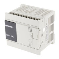
MELSEC-F FX3S-30M series
Brand:
Mitsubishi Electric
| Category:
Controller
| Size: 0.59 MB
Advertisement
Related Products
Mitsubishi Electric FX3S-30MT/ES-2AD
Mitsubishi Electric FX3S-30MT/ESS-2AD
Mitsubishi Electric FX3S-30MR/ES
Mitsubishi Electric FX3S-10MR/ES
Mitsubishi Electric FX3S-14MR/ES
Mitsubishi Electric FX3S-20MR/ES
Mitsubishi Electric FX3S-10M
Mitsubishi Electric FX3U-80MR/ES-A
Mitsubishi Electric FX3U-128MT/ES-A
Mitsubishi Electric FX3G-60MR/DS
Mitsubishi Electric Categories
Air Conditioner
Controller
Projector
Inverter
Heat Pump
More Mitsubishi Electric Manuals
Login
Sign In
OR
Sign in with Facebook
Sign in with Google
Upload manual
Upload from disk
Upload from URL