Sign In
Upload
Manuals
Brands
Siemens Manuals
DC Drives
SINAMICS G115D
Siemens SINAMICS G115D Manuals
Manuals and User Guides for Siemens SINAMICS G115D. We have
3
Siemens SINAMICS G115D manuals available for free PDF download: Operating Instructions Manual
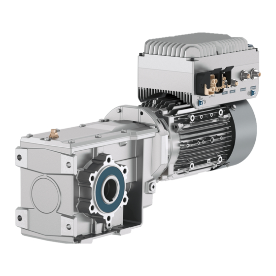
Siemens SINAMICS G115D Operating Instructions Manual (600 pages)
Distributed drive for conveyor applications
Brand:
Siemens
| Category:
DC Drives
| Size: 38.66 MB
Table of Contents
Preface
5
Table of Contents
7
Changes in the Manual
17
Fundamental Safety Instructions
19
General Safety Instructions
19
Equipment Damage Due to Electric Fields or Electrostatic Discharge
25
Warranty and Liability for Application Examples
25
Cybersecurity Information
25
Residual Risks of Power Drive Systems
27
Overview of the SINAMICS G115D Drive
29
System Overview
29
Scope of Delivery
30
SINAMICS G115D Wall Mounted
30
Directives and Standards
35
Optional Components
36
External Braking Resistor
36
Connectors
37
Glanded Installation Kit
38
Connector Cover Kit
38
SINAMICS G120 Smart Access
39
SAM Interface Kit
39
Mounting
41
Mounting the G115D Wall Mounted Drive
41
Mounting the Optional Components
44
Mounting the External Braking Resistor
44
Mounting the SINAMICS G120 Smart Access
46
Wiring
51
EMC Installation Guidelines
51
Connections and Interference Suppression
51
Basic EMC Rules
51
Equipotential Bonding
52
Permissible Line Supplies
54
TN Line System
55
TT Line System
55
Line System
56
Requirements for the Protective Conductor
59
Requirements for Branch Circuit Protection
60
Operation with Residual Current Protective Device (RCD)
60
Forming DC Link Capacitors
61
Overview of the Converter Interfaces
62
Overview
62
Cables and Connectors
66
Maximum Permissible Cable Length
67
Cable Cross-Sections and Cable Lugs
68
Connecting the Line Supply
71
Interface Description - X1/X3
71
Connecting to the Line Supply Using Daisy Chain
73
Connecting the Motor
75
Interface Description - X2
76
Connecting the Motor in a Star or Delta Connection
77
Overview
77
Configuring the Star/Delta Connection of the Wall-Mounted Converter
79
Connecting the 24 V Power Supply
79
Interface Description - X01/X02
79
Connecting to the 24 V Power Supply Using Daisy Chain
81
Connecting the Digital Inputs and Outputs
83
Interface Description - X07/X08/X05
83
Factory Interface Setting
84
Fail-Safe Digital Input
90
Connecting to PROFINET and Ethernet
91
Interface Description - X150 P1/P2
91
Communication Via PROFINET IO and Ethernet
91
Protocols Used
92
Connecting the Converter to PROFINET
94
What Do You Have to Set for Communication Via PROFINET
94
Installing GSDML
95
Connecting the Converter to Ethernet/Ip
96
What Do You Need for Communication Via Ethernet/Ip
96
Connecting to AS-I
97
General Information
97
Interface Description - X03
98
Setting the Address
98
Using the AS-I Programmer
100
Connecting to SINAMICS G115D I/O Variant
102
Grounding the Converter Housing
102
Connecting the External Braking Resistor
103
Connection Examples
105
Commissioning
107
Commissioning Guidelines
107
Commissioning Tools
108
Preparing for Commissioning
109
Factory Settings
109
Collecting Motor Data
111
Selecting U/F Control or Speed Control
113
Calculating Maximum Speed for Permanent Magnet Synchronous Motors
114
Quick Commissioning
115
Quick Commissioning with DIP Switches
115
Quick Commissioning with a PC (Startdrive)
118
Creating a Project
119
Integrating the Converter into the Project
119
Starting the Commissioning Wizard
121
Carrying out Quick Commissioning
121
Identifying Motor Data
123
Quick Commissioning with the SINAMICS G120 Smart Access
125
Self-Optimization of the Speed Control
126
Saving the Settings in the Converter (RAM → EEPROM)
126
Restoring the Factory Settings
127
Restoring the Factory Settings/Delivery Condition (Without Safety Functions)
128
Resetting the Safety Functions to the Factory Settings
129
Advanced Commissioning
131
Overview of Converter Functions
131
Sequence Control When Switching the Motor on and off
133
Adapt the Default Settings of the Inputs and Outputs
135
Overview
135
Digital Inputs
136
Digital Outputs
137
Controlling Clockwise and Counter-Clockwise Rotation Via Digital Inputs
138
Two-Wire Control, Method 1
139
Two-Wire Control, Method 2
140
Two-Wire Control, Method 3
141
Three-Wire Control, Method 1
142
Three-Wire Control, Method 2
143
Drive Control Via PROFINET
144
Receive Data and Send Data
144
Telegrams
145
Control and Status Word 1
147
Control and Status Word 3
149
Control and Status Word G115D
150
NAMUR Message Word
152
Parameter Channel
152
Expanding or Freely Interconnecting Telegrams
156
Acyclically Reading and Writing Converter Parameters
158
Drive Control Via Ethernet/Ip
159
Configuring Communication Via Ethernet/Ip
159
Supported Objects
162
Supported ODVA AC/DC Assemblies
173
Creating Generic I/O Module
174
The Converter as Ethernet Node
175
Drive Control Via AS-I
175
Single Slave Mode
175
Dual Slave Mode
177
Assignment Tables
180
Cyclic and Acyclic Communication Via CTT2
182
Cyclic Communication
183
Acyclic Communication - Standard
184
Acyclic Communication - Manufacturer-Specific
184
Jogging
186
Conveyor Technology Control Functions (for G115D PROFINET and AS-I Variants Only)
187
Conveyors
188
Conveyor, One Direction and One Speed (P3393 = 1)
188
Conveyor, One Direction and Two Speeds (P3393 = 2)
190
Conveyor, Two Directions and One Speed (P3393 = 3)
192
Conveyor, Two Directions and Two Speeds (P3393 = 4)
194
Turntables
196
Turntable, Two Positions and One Speed (P3393 = 5)
197
Turntable, Two Positions and Two Speeds (P3393 = 6)
200
Turntable, Three Positions and One Speed (P3393 = 7)
204
Turntable, Three Positions and Two Speeds (P3393 = 8)
207
Corner Turntable Lifts
210
Corner Turntable Lift, Two Positions and One Speed (P3393 = 9)
211
Corner Turntable Lift, Two Positions and Two Speeds (P3393 = 10)
214
Travelling Trolleys
216
Travelling Trolley, One Speed (P3393 = 11)
217
Travelling Trolley, Two Speeds (P3393 = 12)
219
Conveyor Technology Control Parameters
222
Switching over the Drive Control (Command Data Set)
224
7.11 Motor Holding Brake
226
Encoder Interface
231
Free Function Block
232
Selecting Physical Units
232
Motor Standard
232
System of Units
233
Technological Unit of the Technology Controller
234
Setting the System of Units and Technology Unit
235
Safe Torque off (STO) Safety Function
235
Function Description
236
Commissioning STO
238
Commissioning Tool
238
Safety Function Password
238
Configuring a Safety Function
239
Interconnecting the "STO Active" Signal
240
Setting the Filter for Fail-Safe Digital Inputs
241
Setting the Forced Checking Procedure (Test Stop)
244
Finalizing Online Commissioning
245
Checking the Interconnection of Digital Inputs
247
Acceptance - Completion of Commissioning
248
Safely Limited Speed (SLS)
249
Setpoints
257
Overview
257
Specifying the Setpoint Via the Fieldbus
258
Electromechanical Potentiometer
259
Motorized Potentiometer as Setpoint Source
260
Fixed Speed Setpoint as Setpoint Source
264
Setpoint Processing
267
Overview
267
Invert Setpoint
268
Inhibit Direction of Rotation
269
Skip Frequency Bands and Minimum Speed
270
Speed Limitation
271
Ramp-Function Generator
272
PID Technology Controller
277
Motor Control
284
Setting the Saturation Characteristic of the Permanent Magnet Synchronous Motor (Third-Party Motor)
284
U/F Control
286
Characteristics of U/F Control
287
Selecting the U/F Characteristic
288
Optimizing Motor Starting
289
Sensorless Vector Control with Speed Controller
291
Structure of Vector Control Without Encoder (Sensorless)
291
Optimizing the Closed-Loop Speed Controller
293
Advanced Settings
295
Optimizing the Operation of the Permanent Magnet Synchronous Motor
297
Friction Characteristic
299
Moment of Inertia Estimator
301
Pole Position Identification
308
Torque Control
310
Electrically Braking the Motor
311
DC Braking
312
Dynamic Braking
315
Overcurrent Protection
317
Converter Protection Using Temperature Monitoring
318
Motor Temperature Monitoring Using a Temperature Sensor
322
Motor Protection by Calculating the Temperature
325
Motor and Converter Protection by Limiting the Voltage
327
Monitoring the Driven Load
329
Load Monitoring
329
Rotation Monitoring
330
Torque Monitoring
331
Blocking Protection, Leakage Protection and Dry-Running Protection
333
7.28 Efficiency Optimization
336
Calculating the Energy Saving for Fluid Flow Machines
339
Switchover between Different Settings
342
Activating Licensed Functions
344
Licensing
344
Creating or Displaying the License Key
345
Writing the License Key to the Card
347
Recommended Memory Cards
349
Data Backup and Series Commissioning
353
Transferring Settings Using a Memory Card
354
Memory Cards
354
Converter → Memory Card
355
Memory Card → Converter
357
Activating Message for a Memory Card that Is Not Inserted
359
Transferring Settings Using a PG/PC
360
Converter → PG/PC
360
PG/PC → Converter
361
Other Ways to Back up Settings
363
Write Protection
363
Know-How Protection
364
Extending the Exception List for Know-How Protection
366
Activating and Deactivating Know-How Protection
368
Alarms, Faults and System Messages
371
Status LED Overview
371
System Runtime
375
Identification & Maintenance Data (I&M)
375
Alarms, Alarm Buffer, and Alarm History
376
Faults, Fault Buffer and Fault History
380
List of Alarms and Faults
383
Corrective Maintenance
389
Spare Parts Compatibility
389
Replacing the Converter
390
Replacing the Converter Hardware
390
Replacing a Converter with Active Know-How Protection
392
Replacing a Converter with Know-How Protection Without Copy Protection
392
Replacing a Converter with Know-How Protection with Copy Protection
392
Replacing the Spare Parts
394
Spare Parts Overview
395
Replacing the Electronic Module
396
Replacing the Fan Unit
398
Repair Switch
400
Local/Remote Control Panel
401
Firmware Upgrade and Downgrade
403
Preparing the Memory Card
405
Upgrading the Firmware
405
Downgrading the Firmware
408
Correcting an Unsuccessful Firmware Upgrade or Downgrade
410
Reduced Acceptance Test after Component Replacement and Firmware Change
411
Technical Data
413
Technical Data of the G115D Wall-Mounted Converter
413
General Converter Technical Data
413
Technical Data of Inputs and Outputs
415
Technical Data Dependent Upon the Power
415
Technical Data of Braking Resistors
417
Load Cycles and Overload Capabilities
419
Derating Data
420
Torque Derating as a Function of the Installation Altitude
420
Current Derating as a Function of the Surrounding Temperature
421
Torque Derating as a Function of the Line Voltage
421
Current Derating as a Function of the Pulse Frequency
422
Derating of Motor Cable Length Based on Pulse Frequency and Surrounding Temperature
423
Low Frequency Operation
423
Data Regarding the Power Loss in Partial Load Operation
424
Electromagnetic Compatibility of the Converter
424
Protecting Persons from Electromagnetic Fields
426
Additional Information on the SIMOGEAR Geared Motor
429
General Information Geared Motor with SINAMICS G115D Motor Mounted / Wall Mounted
429
Specific Hazard Types and Fundamental Obligations
429
Rating Plate
430
Surface Treatment
430
General Information on Surface Treatment
430
Painted Version
431
Primed Version
433
Incoming Goods
433
General Information on Transport
434
Unpacking
435
General Information Concerning the Installation
435
Installation Notes
437
Thread Sizes and Tightening Torques for Fastening Bolts
438
Operation
439
Cleaning the Geared Motor
439
Inspecting the Geared Motor
440
Disposal
440
Technical Data
441
Type Designation Motor and Converter
441
Gearbox Type Designation
442
Advertisement
Siemens SINAMICS G115D Operating Instructions Manual (552 pages)
Distributed drive for conveyor technology control
Brand:
Siemens
| Category:
DC Drives
| Size: 39.42 MB
Table of Contents
Preface
5
Table of Contents
7
Fundamental Safety Instructions
17
General Safety Instructions
17
Equipment Damage Due to Electric Fields or Electrostatic Discharge
22
Warranty and Liability for Application Examples
22
Security Information
23
Residual Risks of Power Drive Systems
24
Overview of the SINAMICS G115D Drive
25
System Overview
25
Scope of Delivery
26
SINAMICS G115D Motor Mounted
26
SINAMICS G115D Wall Mounted
28
Directives and Standards
32
Optional Components
33
External Braking Resistor
33
Connectors
34
Glanded Installation Kit
34
Connector Cover Kit
35
SINAMICS G120 Smart Access
35
SAM Interface Kit
36
Mounting
37
Mounting the G115D Motor Mounted Drive
37
Mounting the G115D Wall Mounted Drive
40
Mounting the Optional Components
42
Mounting the External Braking Resistor
42
Mounting the SINAMICS G120 Smart Access
44
Wiring
47
EMC Installation Guidelines
47
Connections and Interference Suppression
47
Basic EMC Rules
47
Equipotential Bonding
48
Permissible Line Supplies
50
TN Line System
51
TT Line System
51
Line System
52
Requirements for the Protective Conductor
55
Requirements for Branch Circuit Protection
56
Operation with Residual Current Protective Device (RCD)
56
Forming DC Link Capacitors
57
Overview of the Converter Interfaces
58
Cables and Connectors
64
Maximum Permissible Cable Length
65
Cable Cross-Sections and Cable Lugs
66
Connecting the Line Supply
69
Interface Description - X1/X3
69
Connecting to the Line Supply Using Daisy Chain
71
Connecting the Motor
72
Interface Description - X2
73
Connecting the Motor in a Star or Delta Connection
74
Overview
74
Configuring the Star/Delta Connection of the Wall-Mounted Converter
75
Connecting the 24 V Power Supply
75
Interface Description - X01/X02
75
Connecting to the 24 V Power Supply Using Daisy Chain
77
Connecting the Digital Inputs and Outputs
78
Interface Description - X07/X08/X05
78
Factory Interface Setting
79
Fail-Safe Digital Input
84
Connecting to PROFINET and Ethernet
84
Interface Description - X150 P1/P2
84
Communication Via PROFINET IO and Ethernet
85
Protocols Used
86
Connecting the Converter to PROFINET
88
What Do You Have to Set for Communication Via PROFINET
88
Installing GSDML
89
Connecting the Converter to Ethernet/Ip
90
What Do You Need for Communication Via Ethernet/Ip
90
Connecting to AS-I
91
General Information
91
Interface Description - X03
92
Setting the Address
92
Using the AS-I Programmer
94
Connecting to SINAMICS G115D I/O Variant
96
Grounding the Converter Housing
96
Connecting the External Braking Resistor
96
Connection Examples
98
Commissioning
101
Commissioning Guidelines
101
Commissioning Tools
102
Preparing for Commissioning
103
Factory Settings
103
Collecting Motor Data
105
Selecting U/F Control or Speed Control
107
Quick Commissioning
108
Quick Commissioning with DIP Switches
108
Quick Commissioning with a PC (Startdrive)
110
Creating a Project
111
Integrating the Converter into the Project
111
Starting the Commissioning Wizard
113
Carrying out Quick Commissioning
113
Identifying Motor Data
115
Quick Commissioning with the SINAMICS G120 Smart Access
117
Saving the Settings in the Converter (RAM → EEPROM)
118
Restoring the Factory Settings
119
Restoring the Factory Settings/Delivery Condition (Without Safety Functions)
120
Resetting the Safety Functions to the Factory Settings
121
Advanced Commissioning
123
Overview of Converter Functions
123
6.2 Sequence Control When Switching the Motor on and off
125
Adapt the Default Settings of the Inputs and Outputs
127
Overview
127
Digital Inputs
128
Digital Outputs
129
Controlling Clockwise and Counter-Clockwise Rotation Via Digital Inputs
130
Two-Wire Control, Method 1
131
Two-Wire Control, Method 2
132
Two-Wire Control, Method 3
133
Three-Wire Control, Method 1
134
Three-Wire Control, Method 2
135
Drive Control Via PROFINET
136
Receive Data and Send Data
136
Telegrams
137
Control and Status Word 1
139
Control and Status Word 3
141
Control and Status Word G115D
142
NAMUR Message Word
143
Parameter Channel
143
Expanding or Freely Interconnecting Telegrams
147
Acyclically Reading and Writing Converter Parameters
149
Drive Control Via Ethernet/Ip
150
Configuring Communication Via Ethernet/Ip
150
Supported Objects
152
Supported ODVA AC/DC Assemblies
162
Creating Generic I/O Module
163
The Converter as Ethernet Node
164
Drive Control Via AS-I
165
Single Slave Mode
165
Dual Slave Mode
167
Assignment Tables
169
Cyclic and Acyclic Communication Via CTT2
171
Cyclic Communication
172
Acyclic Communication - Standard
173
Acyclic Communication - Manufacturer-Specific
173
Jogging
175
Conveyor Technology Control Functions (for G115D PROFINET and AS-I Variants Only)
176
Conveyors
177
Conveyor, One Direction and One Speed (P3393 = 1)
177
Conveyor, One Direction and Two Speeds (P3393 = 2)
179
Conveyor, Two Directions and One Speed (P3393 = 3)
181
Conveyor, Two Directions and Two Speeds (P3393 = 4)
182
Turntables
184
Turntable, Two Positions and One Speed (P3393 = 5)
185
Turntable, Two Positions and Two Speeds (P3393 = 6)
188
Turntable, Three Positions and One Speed (P3393 = 7)
191
Turntable, Three Positions and Two Speeds (P3393 = 8)
194
Corner Turntable Lifts
196
Corner Turntable Lift, Two Positions and One Speed (P3393 = 9)
197
Corner Turntable Lift, Two Positions and Two Speeds (P3393 = 10)
200
Travelling Trolleys
203
Travelling Trolley, One Speed (P3393 = 11)
203
Travelling Trolley, Two Speeds (P3393 = 12)
206
Conveyor Technology Control Parameters
208
Switching over the Drive Control (Command Data Set)
210
Motor Holding Brake
212
Free Function Block
216
Selecting Physical Units
216
Motor Standard
216
System of Units
217
Technological Unit of the Technology Controller
218
Setting the System of Units and Technology Unit
219
Safe Torque off (STO) Safety Function
219
Function Description
220
Commissioning STO
222
Commissioning Tool
222
Safety Function Password
222
Configuring a Safety Function
223
Interconnecting the "STO Active" Signal
224
Setting the Filter for Fail-Safe Digital Inputs
224
Setting the Forced Checking Procedure (Test Stop)
227
Finalizing Online Commissioning
228
Checking the Interconnection of Digital Inputs
229
Acceptance - Completion of Commissioning
230
Setpoints
232
Overview
232
Specifying the Setpoint Via the Fieldbus
233
Electromechanical Potentiometer
234
Motorized Potentiometer as Setpoint Source
235
Fixed Speed Setpoint as Setpoint Source
238
Setpoint Processing
241
Overview
241
Invert Setpoint
241
Inhibit Direction of Rotation
242
Skip Frequency Bands and Minimum Speed
243
Speed Limitation
245
Ramp-Function Generator
246
PID Technology Controller
250
Motor Control
256
U/F Control
257
Characteristics of U/F Control
258
Selecting the U/F Characteristic
259
Optimizing Motor Starting
260
Sensorless Vector Control with Speed Controller
262
Structure of Vector Control Without Encoder (Sensorless)
262
Optimizing the Closed-Loop Speed Controller
264
Advanced Settings
266
Friction Characteristic
268
Moment of Inertia Estimator
270
Pole Position Identification
276
Torque Control
277
Electrically Braking the Motor
278
DC Braking
279
Dynamic Braking
282
Overcurrent Protection
283
Converter Protection Using Temperature Monitoring
284
Motor Temperature Monitoring Using a Temperature Sensor
287
Motor Protection by Calculating the Temperature
290
Motor and Converter Protection by Limiting the Voltage
292
Monitoring the Driven Load
293
No-Load Monitoring
294
Rotation Monitoring
294
Torque Monitoring
295
Blocking Protection, Leakage Protection and Dry-Running Protection
297
Efficiency Optimization
300
Calculating the Energy Saving for Fluid Flow Machines
303
Switchover between Different Settings
305
Data Backup and Series Commissioning
307
Transferring Settings Using a Memory Card
307
Memory Cards
307
Converter → Memory Card
309
Memory Card → Converter
310
Activating Message for a Memory Card that Is Not Inserted
312
Transferring Settings Using a PG/PC
313
Converter → PG/PC
313
PG/PC → Converter
314
Other Ways to Back up Settings
316
Write Protection
316
Know-How Protection
317
Extending the Exception List for Know-How Protection
319
Activating and Deactivating Know-How Protection
320
Alarms, Faults and System Messages
323
Status LED Overview
323
System Runtime
326
Identification & Maintenance Data (I&M)
327
Alarms, Alarm Buffer, and Alarm History
328
Faults, Fault Buffer and Fault History
331
List of Alarms and Faults
334
Corrective Maintenance
339
Spare Parts Compatibility
339
Replacing the Converter
340
Replacing the Converter Hardware
340
Replacing a Converter with Active Know-How Protection
342
Replacing a Converter with Know-How Protection Without Copy Protection
342
Replacing a Converter with Know-How Protection with Copy Protection
342
Replacing the Spare Parts
344
Spare Parts Overview
344
Replacing the Electronic Module
346
Replacing the Fan Unit
348
Repair Switch
349
Local/Remote Control Panel
351
Firmware Upgrade and Downgrade
353
Preparing the Memory Card
354
Upgrading the Firmware
354
Downgrading the Firmware
357
Correcting an Unsuccessful Firmware Upgrade or Downgrade
359
Reduced Acceptance Test after Component Replacement and Firmware Change
360
Technical Data
361
Technical Data of the G115D Converter with SIMOGEAR Geared Motor
361
General Technical Data
361
Technical Data of Inputs and Outputs
363
Technical Data Dependent Upon the Power
364
Technical Data of Braking Resistors
365
Load Cycles and Overload Capabilities
366
Derating Data
368
Torque Derating as a Function of the Installation Altitude
368
Torque Derating as a Function of the Surrounding Temperature
368
Toque Derating as a Function of the Line Voltage
369
Torque Derating as a Function of the Pulse Frequency
370
Torque Derating as a Function of the Motor Speed
371
Technical Data of the G115D Wall-Mounted Converter
372
General Converter Technical Data
372
Technical Data of Inputs and Outputs
374
Technical Data Dependent Upon the Power
375
Technical Data of Braking Resistors
376
Load Cycles and Overload Capabilities
378
Derating Data
379
Current Derating as a Function of the Installation Altitude
379
Current Derating as a Function of the Surrounding Temperature
379
Current Derating as a Function of the Line Voltage
380
Current Derating as a Function of the Pulse Frequency
380
Derating of Motor Cable Length Based on Pulse Frequency and Surrounding
381
Temperature
381
Low Frequency Operation
382
Data Regarding the Power Loss in Partial Load Operation
383
10.5 Electromagnetic Compatibility of the Converter
384
Protecting Persons from Electromagnetic Fields
386
Siemens SINAMICS G115D Operating Instructions Manual (522 pages)
Distributed drive
Brand:
Siemens
| Category:
DC Drives
| Size: 43.81 MB
Table of Contents
Preface
5
Table of Contents
7
1 Fundamental Safety Instructions
17
General Safety Instructions
17
Equipment Damage Due to Electric Fields or Electrostatic Discharge
23
Warranty and Liability for Application Examples
23
Security Information
23
Residual Risks of Power Drive Systems
25
2 Overview of the SINAMICS G115D Drive
27
System Overview
27
Scope of Delivery
28
SINAMICS G115D Motor Mounted
28
SINAMICS G115D Wall Mounted
30
Directives and Standards
34
3 Mounting
37
Mounting the G115D Motor Mounted Drive
37
Mounting the G115D Wall Mounted Drive
40
4 Wiring
43
EMC Installation Guidelines
43
Connections and Interference Suppression
43
Basic EMC Rules
43
Equipotential Bonding
44
Permissible Line Supplies
46
TN Line System
47
TT Line System
47
Line System
48
Removing Functional Grounding of the Converter
49
Requirements for the Protective Conductor
50
Requirements for Branch Circuit Protection
52
Operation with Residual Current Protective Device (RCD)
52
Forming DC Link Capacitors
53
Overview of the Converter Interfaces
54
Cables and Connectors
59
Maximum Permissible Cable Length
60
Cable Cross-Sections and Cable Lugs
61
Connecting the Line Supply
64
Interface Description - X1/X3
64
Connecting to the Line Supply Using Daisy Chain
65
Connecting the Motor
67
Interface Description - X2
67
Connecting the Motor in a Star or Delta Connection
68
Overview
68
Configuring the Star/Delta Connection of the Wall-Mounted Converter
69
Connecting the 24 V Power Supply
70
Interface Description - X01/X02
70
Connecting to the 24 V Power Supply Using Daisy Chain
72
Connecting the Digital Inputs and Outputs
73
Interface Description - X07/X08/X05
73
Factory Interface Setting
75
Fail-Safe Digital Input
75
Connecting to PROFINET and Ethernet
76
Interface Description - X150 P1/P2
76
Communication Via PROFINET IO and Ethernet
76
Protocols Used
78
Connecting the Converter to PROFINET
79
What Do You Have to Set for Communication Via PROFINET
80
Installing GSDML
81
Connecting the Converter to Ethernet/Ip
81
What Do You Need for Communication Via Ethernet/Ip
82
Grounding the Converter Housing
82
Connection Examples
83
5 Commissioning
85
Commissioning Guidelines
85
Commissioning Tools
86
Preparing for Commissioning
86
Factory Settings
86
Collecting Motor Data
88
Selecting U/F Control or Speed Control
90
Quick Commissioning
91
Quick Commissioning with DIP Switches
91
Quick Commissioning with a PC (Startdrive)
93
Creating a Project
93
Integrating the Converter into the Project
94
Starting the Commissioning Wizard
95
Carrying out Quick Commissioning
96
Identifying Motor Data
97
Saving the Settings in the Converter (RAM → EEPROM)
99
Restoring the Factory Settings
100
Restoring the Factory Settings/Delivery Condition (Without Safety Functions)
100
Resetting the Safety Functions to the Factory Settings
101
6 Advanced Commissioning
103
Overview of Converter Functions
103
6.2 Sequence Control When Switching the Motor on and off
105
Adapt the Default Settings of the Inputs and Outputs
107
Overview
107
Digital Inputs
108
Digital Outputs
109
Controlling Clockwise and Counter-Clockwise Rotation Via Digital Inputs
110
Two-Wire Control, Method 1
111
Two-Wire Control, Method 2
111
Two-Wire Control, Method 3
112
Three-Wire Control, Method 1
113
Three-Wire Control, Method 2
114
Drive Control Via PROFINET
114
Receive Data and Send Data
114
Telegrams
115
Control and Status Word 1
117
Control and Status Word 3
119
Control and Status Word G115D
121
NAMUR Message Word
122
Parameter Channel
122
Expanding or Freely Interconnecting Telegrams
127
Acyclically Reading and Writing Converter Parameters
129
Drive Control Via Ethernet/Ip
129
Configuring Communication Via Ethernet/Ip
129
Supported Objects
132
Supported ODVA AC/DC Assemblies
143
Creating Generic I/O Module
144
The Converter as Ethernet Node
145
Jogging
146
Conveyor Technology Control Functions
146
Conveyors
147
Conveyor, One Direction and One Speed (P3393 = 1)
147
Conveyor, One Direction and Two Speeds (P3393 = 2)
149
Conveyor, Two Directions and One Speed (P3393 = 3)
151
Conveyor, Two Directions and Two Speeds (P3393 = 4)
152
Turntables
154
Turntable, Two Positions and One Speed (P3393 = 5)
155
Turntable, Two Positions and Two Speeds (P3393 = 6)
158
Turntable, Three Positions and One Speed (P3393 = 7)
161
Turntable, Three Positions and Two Speeds (P3393 = 8)
164
Corner Turntable Lifts
167
Corner Turntable Lift, Two Positions and One Speed (P3393 = 9)
167
Corner Turntable Lift, Two Positions and Two Speeds (P3393 = 10)
170
Travelling Trolleys
172
Travelling Trolley, One Speed (P3393 = 11)
172
Travelling Trolley, Two Speeds (P3393 = 12)
175
Conveyor Technology Control Parameters
177
Switching over the Drive Control (Command Data Set)
179
Motor Holding Brake
181
Free Function Block
185
Selecting Physical Units
186
Motor Standard
186
System of Units
187
Technological Unit of the Technology Controller
188
Setting the System of Units and Technology Unit
188
Safe Torque off (STO) Safety Function
189
Function Description
189
Commissioning STO
192
Commissioning Tool
192
Safety Function Password
192
Configuring a Safety Function
193
Interconnecting the "STO Active" Signal
194
Setting the Filter for Fail-Safe Digital Inputs
195
Setting the Forced Checking Procedure (Test Stop)
197
Finalizing Online Commissioning
199
Checking the Interconnection of Digital Inputs
200
Acceptance - Completion of Commissioning
201
Setpoints
202
Overview
202
Specifying the Setpoint Via the Fieldbus
204
Electromechanical Potentiometer
205
Motorized Potentiometer as Setpoint Source
206
Fixed Speed Setpoint as Setpoint Source
209
Setpoint Processing
212
Overview
212
Invert Setpoint
213
Inhibit Direction of Rotation
214
Skip Frequency Bands and Minimum Speed
215
Speed Limitation
216
Ramp-Function Generator
217
PID Technology Controller
222
Motor Control
230
U/F Control
230
Characteristics of U/F Control
231
Selecting the U/F Characteristic
232
Optimizing Motor Starting
233
Sensorless Vector Control with Speed Controller
235
Structure of Vector Control Without Encoder (Sensorless)
235
Optimizing the Closed-Loop Speed Controller
237
Advanced Settings
239
Friction Characteristic
241
Moment of Inertia Estimator
243
Pole Position Identification
250
Torque Control
251
Electrically Braking the Motor
252
DC Braking
253
Dynamic Braking
256
Overcurrent Protection
257
Converter Protection Using Temperature Monitoring
258
Motor Temperature Monitoring Using a Temperature Sensor
261
Motor Protection by Calculating the Temperature
264
Motor and Converter Protection by Limiting the Voltage
266
Monitoring the Driven Load
267
No-Load Monitoring
267
Rotation Monitoring
268
Torque Monitoring
269
Blocking Protection, Leakage Protection and Dry-Running Protection
271
Efficiency Optimization
275
Calculating the Energy Saving for Fluid Flow Machines
278
Switchover between Different Settings
280
7 Data Backup and Series Commissioning
283
Transferring Settings Using a Memory Card
283
Memory Cards
283
Converter → Memory Card
285
Memory Card → Converter
287
Activating Message for a Memory Card that Is Not Inserted
288
Transferring Settings Using a PG/PC
289
Converter → PG/PC
289
PG/PC → Converter
290
Other Ways to Back up Settings
291
Write Protection
292
Know-How Protection
293
Extending the Exception List for Know-How Protection
295
Activating and Deactivating Know-How Protection
296
8 Alarms, Faults and System Messages
299
Status LED Overview
299
System Runtime
302
Identification & Maintenance Data (I&M)
303
Alarms, Alarm Buffer, and Alarm History
304
Faults, Fault Buffer and Fault History
307
List of Alarms and Faults
310
9 Corrective Maintenance
317
Spare Parts Compatibility
317
Replacing the Converter
318
Replacing a Converter with Active Know-How Protection
320
Replacing a Converter with Know-How Protection Without Copy Protection
320
Replacing a Converter with Know-How Protection with Copy Protection
320
Repair Switch
322
Firmware Upgrade and Downgrade
323
Preparing the Memory Card
325
Upgrading the Firmware
325
Downgrading the Firmware
328
Correcting an Unsuccessful Firmware Upgrade or Downgrade
330
Reduced Acceptance Test after Component Replacement and Firmware Change
331
10 Technical Data
333
Technical Data of the G115D Converter with SIMOGEAR Geared Motor
333
General Technical Data
333
Technical Data of Inputs and Outputs
335
Technical Data Dependent Upon the Power
336
Technical Data of Braking Resistors
337
Load Cycles and Overload Capabilities
338
Derating Data
339
Current Derating as a Function of the Installation Altitude
339
Current Derating as a Function of the Line Voltage
339
Current and Torque Derating as a Function of the Motor Speed
340
Technical Data of the G115D Wall-Mounted Converter
341
General Converter Technical Data
341
Technical Data of Inputs and Outputs
343
Technical Data Dependent Upon the Power
343
Technical Data of Braking Resistors
345
Load Cycles and Overload Capabilities
345
Derating Data
346
Current Derating as a Function of the Installation Altitude
346
Current Derating as a Function of the Surrounding Temperature
347
Current Derating as a Function of the Line Voltage
347
Current Derating as a Function of the Pulse Frequency
348
Derating of Motor Cable Length Based on Pulse Frequency and Surrounding
349
Temperature
349
Low Frequency Operation
350
Data Regarding the Power Loss in Partial Load Operation
350
Electromagnetic Compatibility of the Converter
351
Protecting Persons from Electromagnetic Fields
353
Advertisement
Advertisement
Related Products
Siemens SINAMICS G110
Siemens SINAMICS G120D
Siemens SINAMICS G110D
Siemens SINAMICS GL150
Siemens SINAMICS GM150
Siemens Sinamics GM150 6SL3835-2LN44-2AA0
Siemens SINAMICS PERFECT HARMONY GH150
Siemens SINAMICS PERFECT HARMONY GH150 6SL3826
Siemens SINAMICS S150
Siemens SINAMICS G
Siemens Categories
Industrial Equipment
Controller
Control Unit
Oven
Washer
More Siemens Manuals
Login
Sign In
OR
Sign in with Facebook
Sign in with Google
Upload manual
Upload from disk
Upload from URL