Sign In
Upload
Manuals
Brands
Siemens Manuals
DC Drives
SINAMICS S150
Siemens SINAMICS S150 Manuals
Manuals and User Guides for Siemens SINAMICS S150. We have
6
Siemens SINAMICS S150 manuals available for free PDF download: Engineering Manual, Operating Instructions Manual, Manual, Function Manual
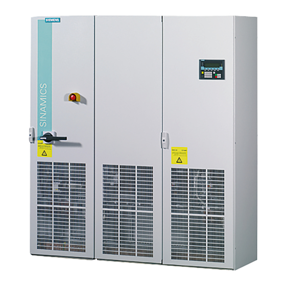
Siemens SINAMICS S150 Engineering Manual (530 pages)
SINAMICS - Low Voltage SINAMICS Drives
Brand:
Siemens
| Category:
DC Drives
| Size: 12.98 MB
Table of Contents
Mechanical Principles
2
Table of Contents
6
1 Fundamental Principles and System Description
16
Operating Principle of SINAMICS Converters
16
General Operating Principle
16
Pulse Modulation Method
16
Generation of a Variable Voltage by Pulse-Width Modulation
17
Maximum Attainable Output Voltage with Space Vector Modulation SVM
18
Maximum Attainable Output Voltage with Pulse-Edge Modulation PEM
19
The Pulse Frequency and Its Influence on Key System Properties
21
Factory Settings and Ranges of Pulse Frequency Settings
21
Interrelationships between Current Controller Clock Cycle, Pulse Frequency and Output Frequency
22
Influence of the Pulse Frequency on the Inverter Output Current
24
Influence of the Pulse Frequency on Losses and Efficiency of Inverter and Motor
24
Influence of the Pulse Frequency on the Motor Noise
24
Correlation between Pulse Frequency and Motor-Side Options
26
Open-Loop and Closed-Loop Control Modes
27
General Information about Speed Adjustment
27
V/F Control Modes
27
Field-Oriented Control Modes
29
Motion Control
30
A Comparison of the Key Features of Open-Loop and Closed-Loop Control Modes
31
Load Balance on Mechanically Coupled Drives
31
Power Ratings of SINAMICS Converters and Inverters / Definition of the Output Power
33
Supply Systems and Supply System Types
35
General
35
Connection of Converters to the Supply System and Protection of Converters
37
Short Circuit Current Rating (SCCR According to UL)
38
Maximum Short-Circuit Currents (SCCR According to IEC) and Minimum Short-Circuit Currents
39
Connection of Converters to Grounded Systems (TN or TT)
44
Connection of Converters to Non-Grounded Systems (IT)
45
Connection of Converters to Supply Systems with Different Short-Circuit Powers
49
Supply Voltage Variations and Supply Voltage Dips
51
Behaviour of SINAMICS Converters During Supply Voltage Variations and Dips
52
Permissible Harmonics on the Supply Voltage
59
Summary of Permissible Supply System Conditions for SINAMICS Converters
60
Line-Side Contactors and Circuit Breakers
61
Transformers
66
Unit Transformers
66
General Information about Calculating the Required Apparent Power of a Unit Transformer
66
Method of Calculating the Required Apparent Power S of a Unit Transformer
68
Transformer Types
69
Features of Standard Transformers and Converter Transformers
70
Three-Winding Transformers
71
Harmonic Effects on the Supply System
72
General
72
Harmonic Currents of 6-Pulse Rectifier Circuits
74
SINAMICS G130, G150, S120 Basic Infeed and S120 Smart Infeed in Motor Operation
74
SINAMICS S120 Smart Infeed in Regenerative Operation
76
Harmonic Currents of 6-Pulse Rectifier Circuits with Line Harmonics Filter
77
SINAMICS Engineering Manual – November
78
Harmonic Currents of 12-Pulse Rectifier Circuits
79
Harmonic Currents and Harmonic Voltages of Active Infeeds (AFE Technology)
80
Standards and Permissible Harmonics
82
Line-Side Reactors and Filters
86
Line Reactors (Line Commutating Reactors)
86
Line Harmonics Filters (LHF and LHF Compact)
87
Operating Principle of Line Harmonics Filters (LHF and LHF Compact)
87
Line Harmonics Filter (LHF) with Separate Housing (6SL3000-0J
88
Line Harmonics Filter Compact (LHF Compact) as Option L01 for SINAMICS G150
90
Line Filters (Radio Frequency Interference (RFI) Suppression Filter or EMC Filter)
92
General Information and Standards
92
Line Filters for the "First" Environment (Residential) and "Second" Environment (Industrial)
95
Operating Principle of Line Filters
95
Magnitude of Leakage or Interference Currents
96
EMC-Compliant Installation
97
SINAMICS Infeeds and Their Properties
100
Basic Infeed
100
Smart Infeed
102
Active Infeed
105
Comparison of the Properties of the Different SINAMICS Infeeds
110
Redundant Line Supply Concepts
112
Permissible Total Cable Length for S120 Infeed Modules Feeding Multi-Motor Drives
117
SINAMICS Braking Units (Braking Modules and Braking Resistors)
118
SINAMICS Inverters or Motor Modules
119
Operating Principle and Properties
119
Drive Configurations with Multiple Motor Modules Connected to a Common DC Busbar
120
Connection of Motor Modules to the DC Busbar, Fuse Protection and Precharging
120
Arrangement of Motor Modules Along the DC Busbar
122
Permissible Dimensions and Topologies of the DC Busbar
125
Short-Circuit Currents on the DC Busbar
127
Maximum Power Rating of Drive Configurations at a Common DC Busbar
129
Effects of Using Fast-Switching Power Components (Igbts)
131
Increased Current Load on the Inverter Output as a Result of Long Motor Cables
131
Special Issues Relating to Motor-Side Contactors and Circuit Breakers
133
Increased Voltage Stress on the Motor Winding as a Result of Long Motor Cables
134
Bearing Currents Caused by Steep Voltage Edges on the Motor
139
Measures for Reducing Bearing Currents
140
EMC-Compliant Installation for Optimized Equipotential Bonding in the Drive System
141
Insulated Bearing at the Non-Drive End (NDE) of the Motor
145
Other Measures
145
Summary of Bearing Current Types and Counter-Measures
146
Motor-Side Reactors and Filters
148
Motor Reactors
148
Reduction of the Voltage Rate-Of-Rise DV/Dt at the Motor Terminals
148
Reduction of Additional Current Peaks When Long Motor Cables Are Used
148
Permissible Motor Cable Lengths with Motor Reactor(S) for Single- and Multi-Motor Drives
149
Supplementary Conditions Which Apply When Motor Reactors Are Used
152
DV/Dt Filters Plus VPL and DV/Dt Filters Compact Plus VPL
153
Design and Operating Principle
153
Supplementary Conditions Which Apply When DV/Dt-Filters Are Used
154
Sine-Wave Filters
155
Design and Operating Principle
155
Supplementary Conditions Which Apply When Sine-Wave Filters Are Used
156
Comparison of the Properties of the Motor-Side Reactors and Filters
157
Power Cycling Capability of IGBT Modules and Inverter Power Units
159
General
159
IGBT Module with Cyclically Alternating Current Load
159
Dimensioning of the Power Units for Operation at Low Output Frequencies
160
Load Duty Cycles
164
General
164
Standard Load Duty Cycles
164
Free Load Duty Cycles
165
Thermal Monitoring of the Power Unit
179
Operation of Converters at Increased Pulse Frequency
179
Efficiency of SINAMICS Converters at Full Load and at Partial Load
183
Converter Efficiency at Full Load
183
Converter Efficiency at Partial Load
184
Partial Load Efficiency of S120 Basic Line Modules
184
Partial Load Efficiency of S120 Smart Line Modules
185
Partial Load Efficiency of S120 Active Line Modules + Active Interface Modules
185
Partial Load Efficiency of S120 Motor Modules
186
Partial Load Efficiency of G130 / G150 Converters
187
Partial Load Efficiency of S150 Converters
190
Parallel Connections of Converters
193
General
193
Parallel Connections of SINAMICS Converters
193
Parallel Connection of S120 Basic Line Modules
195
Parallel Connection of S120 Smart Line Modules
197
Parallel Connection of S120 Active Line Modules
199
Parallel Connection of S120 Motor Modules
201
Admissible and Inadmissible Winding Systems for Parallel Connections of Converters
203
Liquid-Cooled SINAMICS S120 Units
206
General
206
Design of the Liquid-Cooled SINAMICS S120 Units
206
Cooling Circuit and Coolant Requirements
207
Example of a Closed Cooling Circuit for Liquid-Cooled SINAMICS S120 Units
210
Example of an Open Cooling Circuit for Liquid-Cooled SINAMICS S120 Units
210
Example of Coolant Temperature Control for Condensation Prevention
211
Information about Cooling Circuit Configuration
214
Information about Cabinet Design
223
SINAMICS Engineering Manual – November
224
2 EMC Installation Guideline
227
Introduction
227
General
227
EC Directives
227
CE Marking
227
EMC Directive
228
EMC Product Standard en 61800-3
228
Fundamental Principles of EMC
230
Definition of EMC
230
Interference Emissions and Interference Immunity
231
The Frequency Converter and Its EMC
231
The Frequency Converter as a Source of Interference
231
The Frequency Converter as a High-Frequency Source of Interference
232
The Frequency Converter as a Low-Frequency Source of Interference
236
The Frequency Converter as Potentially Susceptible Equipment
237
Methods of Influence
237
Conductive Coupling
237
Capacitive Coupling
238
Inductive Coupling
239
Electromagnetic Coupling (Radiative Coupling)
240
EMC-Compliant Installation
240
Zone Concept Within the Converter Cabinet
241
Converter Cabinet Structure
242
Cables Inside the Converter Cabinet
242
Cables Outside the Converter Cabinet
243
Cable Shields
243
Equipotential Bonding in the Converter Cabinet, in the Drive System, and in the Plant
243
Examples for Installation
245
EMC-Compliant Installation of a SINAMICS G150 Converter Cabinet Unit
245
EMC-Compliant Construction/Installation of a Cabinet with a SINAMICS G130 Chassis Unit
246
EMC-Compliant Cable Routing on the Plant Side on Cable Racks and in Cable Ducts
247
3 General Engineering Information for SINAMICS
249
Overview of Documentation
249
Safety-Integrated / Drive-Integrated Safety Functions
254
Safety Integrated Basic Functions Safe Torque off (STO) und Safe Stop 1 (SS1)
254
Precharging Intervals of the DC Link
258
SINAMICS Booksize Units
258
SINAMICS Chassis Units
258
Operator Panels
258
Basic Operator Panel (BOP20)
258
Advanced Operator Panel (AOP30)
258
Compactflash Cards for CU320-2 Control Units
260
Cabinet Design and Air Conditioning
261
Directives and Standards
261
Physical Fundamental Principles
263
Cooling Air Requirements and Air Opening Cross-Sections in the Cabinet
265
Required Ventilation Clearances
267
Required Partitioning
269
Prevention of Condensation in Equipment Cooled by Air Conditioners and Climate Control Systems
270
Changing the Power Block on Air-Cooled Power Units in Chassis Format
271
Replacement of SIMOVERT P and SIMOVERT a Converter Ranges by SINAMICS
272
General
272
Replacement of Converters in SIMOVERT P 6SE35/36 and 6SC36/37 Ranges by SINAMICS
272
Replacement of Converters in SIMOVERT a Range by SINAMICS
274
4 Converter Chassis Units SINAMICS G130
276
General Information
276
Rated Data of Converters for Drives with Low Demands on Control Performance
279
Connection Diagram of the Power Module
285
Incorporating Different Loads into the 24 V Supply
286
Factory Settings (Defaults) of Customer Interface on SINAMICS G130
287
Cable Cross-Sections and Connections on SINAMICS G130 Chassis Units
292
Precharging of the DC Link and Precharging Currents
292
Line-Side Components
294
Line Fuses
294
Line Reactors
294
Line Harmonics Filters
295
Line Filters
295
Components at the DC Link
296
Braking Units
296
Load-Side Components and Cables
300
Motor Reactors
300
DV/Dt Filters Plus VPL
300
Sine-Wave Filters
300
Maximum Connectable Motor Cable Lengths
300
5 Converter Cabinet Units SINAMICS G150
302
General Information
302
Rated Data of Converters for Drives with Low Demands on Control Performance
302
Factory Settings (Defaults) of Customer Interface on SINAMICS G150 with TM31
309
Cable Cross-Sections and Connections on SINAMICS G150 Cabinet Units
311
Recommended and Max. Possible Cable Cross-Sections for Line and Motor Connections
311
Required Cable Cross-Sections for Line and Motor Connections
313
Grounding and PE Conductor Cross-Section
314
Precharging of the DC Link and Precharging Currents
315
Line-Side Components
317
Line Fuses
317
Line Reactors
317
Line Harmonics Filters
318
Line Filters
318
Components at the DC Link
319
Braking Units
319
Load-Side Components and Cables
323
Motor Reactors
323
DV/Dt Filters Plus VPL and DV/Dt Filters Compact Plus VPL
323
Sine-Wave Filters
323
Maximum Connectable Motor Cable Lengths
324
SINAMICS G150 Parallel Converters (SINAMICS G150 Power Extension)
324
SINAMICS Engineering Manual – November
324
6-Pulse Operation of SINAMICS G150 Parallel Converters
327
12-Pulse Operation of SINAMICS G150 Parallel Converters
328
Operation at Motors with Electrically Isolated and with Common Winding Systems
329
Special Features to Note When Precharging SINAMICS G150 Parallel Converters
331
Overview of SINAMICS G150 Parallel Converters
334
6 General Information about Built-In and Cabinet Units SINAMICS S120
335
General
335
Assignment Table
335
Control Properties
335
Performance Features of the CU320-2 Control Unit
335
Control Properties / Definitions
337
Control Properties of the CU320-2 Control Unit
338
Determination of the Required Control Performance of the CU320-2 Control Unit
345
Rated Data, Permissible Output Currents, Maximum Output Frequencies
348
Permissible Output Currents and Maximum Output Frequencies
348
Ambient Temperatures > 40°C and Installation Altitudes > 2000 M
349
DRIVE-Cliq
351
Basic Information
351
Determination of Component Cabeling
352
DRIVE-Cliq Cables Supplied with the Units
353
Cable Installation
354
Precharging of the DC Link and Precharging Currents
357
Basic Infeed
357
Smart Infeed
359
Active Infeed
361
Checking the Maximum DC Link Capacitance
363
Basic Information
363
Capacitance Values
364
Connection of Motor Modules to a Common DC Busbar
368
Direct Connection to the DC Busbar
368
Braking Modules / External Braking Resistors
369
Braking Modules for Power Units in Chassis Format
369
Braking Resistors for Power Units in Chassis Format
372
SINAMICS S120 Motor Modules as 3-Phase Braking Modules
373
Maximum Connectable Motor Cable Lengths
378
Booksize Units
378
Chassis Units
379
Checking the Total Cable Length for Multi-Motor Drives
380
Parallel Connections of Motor Modules
381
General
381
Minimum Motor Cable Lengths for Motors with Common Winding System
381
Advertisement
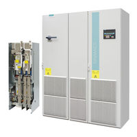
Siemens SINAMICS S150 Operating Instructions Manual (520 pages)
Converter cabinet units 75 kW to 1200 kW
Brand:
Siemens
| Category:
Media Converter
| Size: 8.46 MB
Table of Contents
Preface
5
Table of Contents
7
Safety Information
15
Warnings
15
Safety and Operating Instructions
16
Components that Can be Destroyed by Electrostatic Discharge (ESD)
17
Device Overview
19
Chapter Content
19
Applications, Features, and Design
20
Applications
20
Features, Quality, Service
20
Structure
22
Wiring Principle
24
Type Plate
25
Mechanical Installation
29
Chapter Content
29
Transportation and Storage
30
Installation
32
Mechanical Installation: Checklist
33
Preparation
33
Installation
35
Fitting Additional Canopies (Option M21) or Hoods (Option M23, M43, M54)
35
Infeed from above (Option M13), Motor Connection from above (Option M78)
38
Electrical Installation
41
Chapter Content
41
Checklist for Electrical Installation
42
Important Safety Precautions
47
Introduction to EMC
48
EMC-Compliant Design
50
Power Connections
52
Connection Cross-Sections and Cable Lengths
52
Connecting the Motor and Power Cables
53
Adjusting the Fan Voltage (-G1 -T10, -U1 -T10)
54
Adjusting the Internal Power Supply (-A1-T10)
57
Removing the Connection Bracket for the Interference-Suppression Capacitor with Operation from an Ungrounded Supply
58
External Supply of the Auxiliary Supply from a Secure Line
59
Signal Connections
60
Customer Terminal Block (-A60)
60
Other Connections
67
DV/Dt Filter with Voltage Peak Limiter (Option L10)
67
Sinusoidal Filter (Option L15)
69
Connection for External Auxiliary Equipment (Option L19)
71
Main Switch Incl. Fuses or Main Circuit Breaker (Option L26)
73
EMERGENCY STOP Pushbutton (Option L45)
74
Cabinet Illumination with Service Socket (Option L50)
75
Cabinet Anti-Condensation Heating (Option L55)
76
EMERGENCY STOP Category 0; 230 V AC or 24 V DC (Option L57)
77
EMERGENCY STOP Category 1; 230 V AC (Option L59)
78
EMERGENCY STOP Category 1; 24 V DC (Option L60)
79
Kw Braking Unit (Option L61/L64); 50 Kw Braking Unit (Option L62/L65)
80
Installing the Braking Resistor
80
Thermistor Motor Protection Unit (Option L83/L84)
86
PT100 Evaluation Unit (Option L86)
87
Insulation Monitor (Option L87)
89
Communication Board Ethernet CBE20 (Option G33)
90
SMC10 Sensor Module for Determining the Actual Motor Speed and the Rotor Position Angle (Option K46)
92
Description
92
Connection
93
Connection Example
94
SMC20 Sensor Module for Determining the Actual Motor Speed and the Path Length (Option K48)
96
Description
96
Connection
97
Connection Example
98
SMC30 Sensor Module for Detecting the Actual Motor Speed (Option K50)
100
Description
100
Connection
103
Connection Examples
105
Voltage Sensing Module for Determining the Actual Motor Speed and the Phase Angle (Option K51)
106
Customer Terminal Block Extension (Option G61)
106
Terminal Module for Activation of "Safe Torque Off" and "Safe STOP 1" (Option K82)
107
NAMUR Terminal Block (Option B00)
111
Electrically Separate 24 V DC Power Supply for NAMUR (Option B02)
113
Outgoing Section for External Auxiliary Equipment for NAMUR (Option B03)
113
Commissioning
115
Chapter Content
115
STARTER Commissioning Tool
116
Installing STARTER
116
The STARTER User Interface
117
Procedure for Commissioning Via STARTER
118
Creating a Project
118
Configuring the Drive Unit
127
Starting the Drive Project
153
Connection Via Serial Interface
154
The AOP30 Operator Panel
157
First Commissioning
158
Basic Commissioning
160
Status after Commissioning
168
Commissioning an Encoder with Gear Factor
169
Parameter Reset to Factory Settings
169
Operation
171
Chapter Content
171
General Information about Command and Setpoint Sources
172
Basic Information about the Drive System
173
Parameters
173
Drive Objects
175
Data Sets
177
BICO Technology: Interconnecting Signals
182
Command Sources
187
Profidrive" Default Setting
187
TM31 Terminals" Default Setting
189
NAMUR" Default Setting
191
Profidrive NAMUR" Default Setting_G150_S150
193
Setpoint Sources
195
Analog Inputs
195
Motorized Potentiometer
197
Fixed Speed Setpoints
198
Profibus
200
PROFIBUS Connection
200
Control Via Profibus
203
Monitoring: Telegram Failure
204
Telegrams and Process Data
205
Description of Control Words and Setpoints
207
Description of Status Words and Actual Values
211
Creating an S150 in SIMATIC Manager
217
Control Via the Operator Panel
219
Operator Panel (AOP30) Overview and Menu Structure
219
Menu: Operation Screen
221
Menu: Parameterization
221
Menu: Fault/Alarm Memory
223
Menu: Commissioning / Service
224
Drive Commissioning
224
Device Commissioning
224
AOP30 Settings
224
AOP30 Diagnosis
229
Language/Sprache/Langue/Idioma/Lingua
230
Operation Via the Operator Panel (LOCAL Mode)
230
LOCAL/REMOTE Key
231
ON Key / off Key
231
Switching between Clockwise and Counter-Clockwise Rotation
232
Jog
232
Increase Setpoint / Decrease Setpoint
232
AOP Setpoint
233
Timeout Monitoring
234
Operator Input Inhibit / Parameterization Inhibit
234
Faults and Alarms
235
Saving the Parameters Permanently
237
Parameterization Errors
237
Profinet Io
238
Activating Online Operation: STARTER Via PROFINET IO
238
General Information about PROFINET IO
244
General Information about PROFINET IO for SINAMICS
244
Real-Time (RT) and Isochronous Real-Time (IRT) Communication
244
Addresses
246
Data Transmission
247
Hardware Setup
248
Configuring SINAMICS Drives with PROFINET
248
RT Classes
250
RT Classes for PROFINET IO
250
PROFINET IO with RT
252
Configuring RT Communication on Simatic
252
PROFINET IO with IRT - Overview
255
PROFINET IO with Irtflex
256
PROFINET IO with Irttop
257
Setpoint Channel and Closed-Loop Control
259
Chapter Content
259
Setpoint Channel
260
Setpoint Addition
260
Direction of Rotation Changeover
261
Skip Speeds and Minimum Speeds
262
Speed Limitation
263
Ramp-Function Generator
264
V/F Control
266
Voltage Boost
269
Slip Compensation
272
Vector Speed/Torque Control With/Without Encoder
273
Vector Control Without Encoder
274
Vector Control with Encoder
276
Speed Controller
277
Examples of Speed Controller Settings
279
Speed Controller Pre-Control (Integrated Pre-Control with Balancing)
280
Reference Model
283
Speed Controller Adaptation
284
Droop Function
286
Closed-Loop Torque Control
287
Torque Limiting
290
Permanent-Field Synchronous Motors
291
Output Terminals
295
Chapter Content
295
Analog Outputs
296
Lists of Signals for the Analog Outputs
297
Digital Outputs
299
Functions, Monitoring, and Protective Functions
301
Chapter Content
301
Active Infeed Functions
303
Line and DC Link Identification
303
Harmonics Controller
304
Variable Power Factor (Reactive Power Compensation)
305
Settings for the Infeed (Active Infeed) under Difficult Line Conditions
306
Drive Functions
308
Motor Identification and Automatic Speed Controller Optimization
308
Standstill Measurement
309
Rotating Measurement and Speed Controller Optimization
311
Efficiency Optimization
314
VDC Control
315
Automatic Restart Function
318
Siemens SINAMICS S150 Engineering Manual (396 pages)
Brand:
Siemens
| Category:
DC Drives
| Size: 7.06 MB
Table of Contents
Siemens AG
4
Table of Contents
5
Fundamental Principles and System Description
12
Operating Principle of SINAMICS Converters
12
General Operating Principle
12
Pulse Modulation Method
12
Generation of a Variable Voltage by Pulse Width Modulation
13
Maximum Attainable Output Voltage with Space Vector Modulation SVM
15
Maximum Attainable Output Voltage with Pulse-Edge Modulation PEM
15
The Pulse Frequency and Its Influence on Key System Properties
17
Output Power Ratings of SINAMICS Converters and Inverters / Definition of the Output Power
19
Supply Systems and Supply System Types
21
General
21
Connection of Converters to Grounded Systems (TN or TT)
22
Connection of Converters to Non-Grounded Systems (IT)
22
Connection of Converters to Supply Systems with Different Short-Circuit Powers
23
Supply Voltage Variations and Supply Voltage Dips
25
Behaviour of SINAMICS Converters During Supply Voltage Variations and Dips
26
Permissible Harmonics on the Supply Voltage
32
Transformers
33
Unit Transformers
33
Transformer Types
34
Features of Standard Transformers and Converter Transformers
35
Three-Winding Transformers
36
Harmonic Effects on the Supply System
37
General
37
Harmonic Currents of 6-Pulse Rectifier Circuits
39
Harmonic Currents of 6-Pulse Rectifier Circuits with Line Harmonics Filter
42
Harmonic Currents of 12-Pulse Rectifier Circuits
44
Harmonic Currents and Harmonic Voltages of Active Infeeds (AFE Technology)
45
Standards and Permissible Harmonics
47
Line Reactors (Line Commutating Reactors)
51
Line Harmonics Filter (LHF)
52
Line Filters (Radio Frequency Interference (RFI) Suppression Filters or EMC Filters)
54
General Information and Standards
54
Line Filters for the "First" Environment (Residential) and "Second" Environment (Industrial)
56
Operating Principle of Line Filters
57
Magnitude of Leakage or Interference Currents
57
EMC-Compliant Installation
58
SINAMICS Infeeds and Their Properties
60
Basic Infeed
60
Smart Infeed
62
Active Infeed
64
Comparison of the Properties of the Different SINAMICS Infeeds
67
Redundant Line Supply Concepts
68
Permissible Total Cable Length for S120 Infeed Modules Feeding Multi-Motor Drives
74
Effects of Using Fast-Switching Power Components (Igbts)
75
Increased Current Load on the Inverter Output as a Result of Long Motor Cables
75
Increased Voltage Stress on the Motor Winding as a Result of Long Motor Cables
77
Bearing Currents Caused by Steep Voltage Edges on the Motor
81
Measures for Reducing Bearing Currents
82
EMC-Compliant Installation for Optimized Equipotential Bonding in the Drive System
83
Insulated Bearing at the Non-Drive End (NDE End) of the Motor
86
Other Measures
86
Brief Overview of the Different Types of Bearing Currents
87
Motor Reactors
89
Reduction of the Voltage Rate of Rise DV/Dt at the Motor Terminals
89
Reduction of Additional Current Peaks When Long Motor Cables Are Used
89
Permissible Motor Cable Lengths with Motor Reactor(S) for Single-Motor and Multi-Motor Drives
90
Supplementary Conditions Which Apply When Motor Reactors Are Used
93
DV/Dt Filter Plus VPL
94
Sine-Wave Filters
96
Load Duty Cycles
98
General
98
Standard Load Duty Cycles
98
Free Load Duty Cycles
99
Thermal Monitoring of the Power Unit During Load Duty Cycles and Continuous Operation
102
Efficiency of SINAMICS Converters at Full Load and at Partial Load
103
Converter Efficiency at Full Load
103
Converter Efficiency at Partial Load
104
Parallel Connections of Converters
110
General
110
Parallel Connections of SINAMICS Converters
110
Parallel Connection of S120 Basic Line Modules
112
Parallel Connection of S120 Smart Line Modules
114
Parallel Connection of S120 Active Line Modules
116
Parallel Connection of S120 Motor Modules
116
Admissible and Inadmissible Winding Systems for Parallel Connections of SINAMICS Converters
118
SINAMICS S120 Liquid-Cooled Units in Chassis Format
121
General
121
Design of the SINAMICS S120 Liquid-Cooled Units
121
Requirements Concerning Coolant and Cooling Circuit
122
EMC Installation Guideline
126
Introduction
126
General
126
EC Directives
126
CE Marking
126
EMC Directive
127
EMC Product Standard en 61800-3
127
Fundamental Principles of EMC
129
Definition of EMC
129
Interference Emissions and Interference Immunity
130
The Frequency Converter and Its EMC
130
The Frequency Converter as a Source of Interference
130
The Frequency Converter as a High-Frequency Source of Interference
131
The Frequency Converter as a Low-Frequency Source of Interference
134
The Frequency Converter as Potentially Susceptible Equipment
135
Methods of Influence
135
Conductive Coupling
135
Capacitive Coupling
136
Inductive Coupling
137
Electromagnetic Coupling (Radiative Coupling)
138
EMC-Compliant Installation
138
Zone Concept Within the Converter Cabinet
139
Converter Cabinet Structure
140
Cables Inside the Converter Cabinet
140
Cables Outside the Converter Cabinet
141
Cable Shields
141
Equipotential Bonding in the Converter Cabinet, in the Drive System, and in the Plant
141
Examples for Installation
143
EMC - Compliant Installation of a SINAMICS G150 Converter Cabinet Unit
143
EMC - Compliant Construction / Installation of a Cabinet with a SINAMICS G130 Chassis Unit
144
EMC - Compliant Cable Routing on the Plant Side on Cable Racks and in Cable Routes
145
General Engineering Information for SINAMICS
146
Overview of Documentation
146
Safety-Integrated, Drive-Integrated Safety Functions
150
Safe Torque off (Previously Known as "Safe Standstill") and Safe Stop 1
150
Safe Brake Control
153
Precharging Intervals of the DC Link
155
SINAMICS Booksize Units
155
SINAMICS Chassis Units
155
Operator Panel
155
Basic Operator Panel (BOP20)
155
Advanced Operator Panel (AOP30)
155
Cabinet Construction and Air Conditioning
157
Directives and Standards
157
Cabinet Air Conditioning
158
Cooling Air Requirement and Sizes of Cabinet Openings
160
Partitioning
161
Changing the Power Block on Chassis Power Units
162
Replacement of SIMOVERT P and SIMOVERT a Converter Ranges by SINAMICS
163
General
163
Replacement of Converters in SIMOVERT P 6SE35/36 and 6SC36/37 Ranges by SINAMICS
163
Replacement of Converters in SIMOVERT a 6SC23 Range by SINAMICS
165
Converter Chassis Units SINAMICS G130
167
General Information
167
Rated Data of Converters for Drives with Low Demands on Control Performance
170
Incorporating Different Loads into the 24 V Supply
173
Factory Settings (Defaults) of Customer Interface on SINAMICS G130
174
Line-Side Components
180
Line Fuses
180
Line Reactors
180
Line Filters
181
Components at the DC Link
182
Braking Units
182
Load-Side Components and Cables
185
Motor Reactor
185
DV/Dt Filter Plus VPL
185
Sine-Wave Filter
185
Maximum Connectable Motor Cable Lengths
185
Converter Cabinet Units SINAMICS G150
187
General Information
187
Rated Data of Converters for Drives with Low Demands on Control Performance
187
Factory Settings (Defaults) of Customer Interface on SINAMICS G150
191
Cable Cross-Sections and Connections on SINAMICS G150 Cabinet Units
193
Recommended and Maximum Possible Cable Cross-Sections for Line and Motor Connections
193
Required Cable Cross-Sections for Line and Motor Connections
195
Grounding and PE Conductor Cross-Section
196
Line-Side Components
197
Line Fuses
197
Line Reactors
197
Line Filters
198
Components at the DC Link
199
Braking Units
199
Load-Side Components and Cables
202
Motor Reactor
202
DV/Dt Filter Plus VPL
202
Sine-Wave Filter
202
Maximum Connectable Motor Cable Lengths
202
SINAMICS G150 Parallel Converters (SINAMICS G150 Power Extension)
203
6-Pulse Operation of SINAMICS G150 Parallel Converters
205
12-Pulse Operation of SINAMICS G150 Parallel Converters
207
Operation at Motors with Electrically Isolated Winding Systems and One Common Winding System
208
Special Features to Note When Precharging SINAMICS G150 Parallel Converters
209
Brief Overview of SINAMICS G150 Parallel Converters with Production Date up to Autumn 2007
210
Brief Overview of SINAMICS G150 Parallel Converters with Production Date from Autumn 2007
211
SINAMICS S120, General Information about Built-In and Cabinet Units
212
General
212
Assignment Table
212
Control Properties
212
Performance Features
212
Control Properties, Definitions
214
Closed-Loop Control Characteristics
214
Rating Data
217
Maximum Output Frequencies
217
DRIVE Cliq
218
Basic Informations
218
DRIVE-Cliq Cables Supplied with the Unit
218
Cable Installation
220
Specification of the Required Control Performance and Selection of the Control Unit
223
Specification of Component Cabling
225
Check of the Maximum DC Link Capacitance
228
Basic Informations
228
Capacitance Values
229
Braking Module / External Braking Resistor
233
Braking Module for Power Units in Chassis Format
233
Braking Resistors for Power Units in Chassis Format
235
Maximum Connectable Motor Cable Lengths
237
Booksize Units
237
Chassis Units
238
Checking the Total Cable Length for Multi-Motor Drives
239
Modular Cabinet Unit System SINAMICS S120 Cabinet Modules
240
General
240
Design
240
General Configuring Process
240
Dimensioning and Selection Information
241
Advertisement
Siemens SINAMICS S150 Manual (312 pages)
Safety Integrated
Brand:
Siemens
| Category:
Control Unit
| Size: 5.21 MB
Table of Contents
Preface
5
Table of Contents
11
1 Typicals and Regulations
17
General Information
17
Aims
17
Functional Safety
17
Safety of Machinery in Europe
18
Machinery Directive
18
Harmonized European Standards
19
Standards for Implementing Safety-Related Controllers
21
ISO 13849-1 (Previously en 954-1)
23
Series of Standards en 61508 (VDE 0803)
26
Risk Analysis/Assessment
27
Risk Reduction
29
Residual Risk
29
Machine Safety in the USA
30
Minimum Requirements of the OSHA
30
NRTL Listing
31
Nfpa 79
31
Ansi B11
32
Machine Safety in Japan
32
Equipment Regulations
32
Other Safety-Related Issues
33
Information Sheets Issued by the Employer's Liability Insurance Association
33
Additional References
33
2 General Information about SINAMICS Safety Integrated
35
Safety Integrated Functions
35
Preconditions for Safety Integrated Basic Functions
36
Preconditions for Safety Integrated Extended Functions
37
Controlling the Safety Integrated Functions
37
Parameter, Checksum, Version, Password
39
DRIVE-Cliq Rules for Safety Integrated Functions
42
3 System Features
43
Latest Information
43
Certification
44
Safety Instructions
45
Probability of Failure of the Safety Functions (PFH Value)
47
Response Times
48
Response Times Safety Integrated Basic Functions
48
Response Times, Safety Integrated Extended Functions with Encoder
49
Response Times for Safety Integrated Extended Functions Without Encoder
50
Residual Risk
51
4 Supported Functions
53
Content of this Chapter
53
Sinamics G130
54
Basic Functions
54
Extended Functions
54
Sinamics G150
55
Basic Functions
55
Extended Functions
55
SINAMICS S120 Chassis
56
Basic Functions
56
Extended Functions
57
SINAMICS S120 Cabinet Modules
58
Booksize Format Motor Module
58
Basic Functions
58
Extended Functions
59
Motor Module in Chassis Format
60
Basic Functions
60
Extended Functions
61
Sinamics S150
62
Basic Functions
62
Extended Functions
63
5 Safety Integrated Basic Functions
65
Safe Torque off (STO)
65
Safe Stop 1 (SS1, Time Controlled)
69
Safe Brake Control (SBC)
71
Safety Faults
73
Forced Checking Procedure
75
6 Safety Integrated Extended Functions
77
Safety Functions "With Encoder" / "Without Encoder
77
Safety Licenses for 1 to 5 Axes
78
Safety Licenses for S120 Chassis
78
Option F01 to F05 (Safety Licenses for 1 to 5 Axes)
78
Safety Licenses for S120 Cabinet Modules and S150
79
Option K01 to K05 (Safety Licenses for 1 to 5 Axes)
79
Safe Torque off (STO)
81
Safe Stop 1 (SS1)
82
Safe Stop 1 with Encoder (Time and Acceleration Controlled)
82
Safe Stop 1 Without Encoder (Time and Speed Controlled)
84
Overview of Important Parameters
86
Safe Stop 2 (SS2)
87
General Description
87
EPOS and Safe Stop 2
89
Safe Operating Stop (SOS)
90
Safely-Limited Speed (SLS)
92
General Description
92
Parking Note
93
Safely-Limited Speed with Encoder
93
Safely-Limited Speed Without Encoder
94
Overview of Important Parameters
97
EPOS and Safely-Limited Speed
98
Safe Speed Monitor (SSM)
99
Safe Acceleration Monitor (SBR)
102
Safe Brake Ramp (SBR)
104
Safety Faults
107
Message Buffer
112
Reliable Actual Value Acquisition with the Encoder System
114
Forced Dormant Error Detection
119
7 Controlling the Safety Functions
123
Overview of F-DI/F-Dos and of Their Structure
123
Control of "STO" and "SS1" Via Terminal Module for Option K82
124
Terminal Module for Control of "STO" and "SS1" for SINAMICS G150
124
Terminal Module for Control of "STO" and "SS1" for SINAMICS S120 Cabinet Modules
129
General Information
129
Use of the K82 Option with Control Unit CU320-2
133
Wiring
133
Terminal Module for Control of "STO" and "SS1" for SINAMICS S150
134
Control of "STO" and "SS1" Via Terminals on the Control Unit and the Motor/Power Module
139
General Information
139
Control Signals by Way of Terminals on the Control Unit and Motor/Power Module
139
Simultaneity and Tolerance Time of the Two Monitoring Channels
143
Bit Pattern Test
144
Control of "STO" and "SS1" for SINAMICS G130
145
Control of "STO" and "SS1" for SINAMICS G150
151
Control of "STO" and "SS1" for SINAMICS S120 Chassis
157
Control of "STO" and "SS1" for SINAMICS S120 Cabinet Modules
163
Control of "STO" and "SS1" for SINAMICS S150
169
Control Via TM54F / Option K87
175
General Information
175
TM54F Design
175
F-DI Function
176
Function of the F-DO
178
Control Via TM54F for SINAMICS S120 Chassis
180
Control Via Option K87 for SINAMICS S120 Cabinet Modules
180
Control Via K87 for SINAMICS S150
180
Control by Way of Profisafe
181
Safety Integrated Functions
181
Enabling of the Control Via Profisafe
181
Structure of Telegram 30
182
Structure of Telegram 30 (Basic Functions)
182
Structure of Telegram 30 (Extended Functions)
184
Siemens SINAMICS S150 Function Manual (108 pages)
Chassis, Cabinet Modules
Brand:
Siemens
| Category:
Industrial Equipment
| Size: 1.93 MB
Table of Contents
Preface
5
Table of Contents
7
Safety Information
9
Industrial Security
10
Introduction
13
General Information about SINAMICS Safety Integrated
15
Supported Functions
15
Sinamics G130
19
Basic Functions
19
Extended Functions
20
Sinamics G150
21
Basic Functions
21
Extended Functions
22
SINAMICS S120 Chassis and Chassis-2
23
Basic Functions
23
Extended Functions
23
Advanced Functions
25
SINAMICS S120 Cabinet Modules, Booksize Format
26
Basic Functions
26
Extended Functions
27
SINAMICS S120 Cabinet Modules, Chassis and Chassis-2 Formats
28
Basic Functions
28
Extended Functions
29
Sinamics S150
30
Basic Functions
30
Extended Functions
31
Drive Monitoring with or Without Encoder
32
Description of Safety Integrated Functions
33
Preconditions for Safety Integrated Basic Functions
33
Preconditions for Safety Integrated Extended Functions
34
Preconditions for Safety Integrated Advanced Functions
35
Controlling the Safety Functions
37
Control Possibilities
37
Control of "STO" and "SS1" Via Terminal Module for Option K82
38
Terminal Module for Control of "STO" and "SS1" for SINAMICS G150
38
Terminal Module for Control of "STO" and "SS1" for SINAMICS S120 Cabinet Modules
44
General Information
44
Use of the K82 Option with Control Unit CU320-2
47
Use of the K82 Option with Control Unit CU320-2
48
Wiring
48
Terminal Module for Control of "STO" and "SS1" for SINAMICS S150
49
Technical Data
53
Control of "STO" and "SS1" Via Terminals on the Control Unit and the Motor/Power Module
54
Simultaneity and Tolerance Time of the Two Monitoring Channels
57
Bit Pattern Test
59
Control of "STO" and "SS1" for SINAMICS G130
60
Control of "STO" and "SS1" for SINAMICS G150
66
Control of "STO" and "SS1" for SINAMICS S120 Chassis and Chassis-2
72
Control of "STO" and "SS1" for SINAMICS S120 Cabinet Modules
78
Control of "STO" and "SS1" for SINAMICS S150
84
Siemens SINAMICS S150 Function Manual (102 pages)
Brand:
Siemens
| Category:
DC Drives
| Size: 1.14 MB
Table of Contents
Preface
5
Table of Contents
7
1 Safety Information
9
Industrial Security
10
2 Introduction
13
3 General Information about SINAMICS Safety Integrated
15
Supported Functions
15
Sinamics G130
18
Basic Functions
18
Extended Functions
18
Sinamics G150
20
Basic Functions
20
Extended Functions
20
SINAMICS S120 Chassis
22
Basic Functions
22
Extended Functions
22
SINAMICS S120 Cabinet Modules, Booksize Format
24
Basic Functions
24
Extended Functions
24
SINAMICS S120 Cabinet Modules, Chassis Format
26
Basic Functions
26
Extended Functions
26
Sinamics S150
28
Basic Functions
28
Extended Functions
28
Drive Monitoring with or Without Encoder
29
4 Description of Safety Integrated Functions
31
Preconditions for Safety Integrated Basic Functions
31
Preconditions for Safety Integrated Extended Functions
32
5 Controlling the Safety Functions
33
Control Possibilities
33
Control of "STO" and "SS1" Via Terminal Module for Option K82
34
Terminal Module for Control of "STO" and "SS1" for SINAMICS G150
34
Terminal Module for Control of "STO" and "SS1" for SINAMICS S120 Cabinet Modules
39
General Information
39
Use of the K82 Option with Control Unit CU320-2
43
Use of the K82 Option with Control Unit CU320-2
44
Wiring
44
Terminal Module for Control of "STO" and "SS1" for SINAMICS S150
44
Control of "STO" and "SS1" Via Terminals on the Control Unit and the Motor/Power Module
50
Simultaneity and Tolerance Time of the Two Monitoring Channels
53
Bit Pattern Test
55
Control of "STO" and "SS1" for SINAMICS G130
56
Control of "STO" and "SS1" for SINAMICS G150
62
Control of "STO" and "SS1" for SINAMICS S120 Chassis
68
Control of "STO" and "SS1" for SINAMICS S120 Cabinet Modules
74
Control of "STO" and "SS1" for SINAMICS S150
80
Activating "SBC" Via the Safe Brake Adapter
86
Activating "SBC" Via the Safe Brake Adapter for Option K88 (230 V AC)
86
Safe Brake Adapter SBA 230 V AC for SINAMICS G130/SINAMICS S120 Chassis
90
Control by Way of Profisafe
95
Control Via TM54F
96
Control Via TM54F for SINAMICS G130, S120 Chassis
96
Control Via Option K87 for SINAMICS S120 Cabinet Modules
96
Control Via K87 for SINAMICS S150
96
Motion Monitoring Without Selection
97
Advertisement
Related Products
Siemens SINAMICS G
Siemens SINAMICS V20 Series
Siemens SINAMICS G Series
Siemens SINAMICS SL150
Siemens SIMOREG DC-MASTER
SIEMENS SIMOVERT MASTERDRIVE Series
SIEMENS SIMOVERT SLP
Siemens SIMOGEAR BA 2030
Siemens SIMOVERT FC
Siemens SIMOVERT VC
Siemens Categories
Industrial Equipment
Controller
Control Unit
Oven
Washer
More Siemens Manuals
Login
Sign In
OR
Sign in with Facebook
Sign in with Google
Upload manual
Upload from disk
Upload from URL