ABB REL670 Operator's Manual
Line distance protection
Hide thumbs
Also See for REL670:
- Installation and commissioning manual (198 pages) ,
- Product manual (150 pages) ,
- Commissioning manual (284 pages)
Table of Contents
Advertisement
Quick Links
Download this manual
See also:
Installation Manual
Advertisement
Table of Contents

Related Manuals for ABB REL670


Summary of Contents for ABB REL670
- Page 1 ® Relion 670 series Line distance protection REL670 ANSI Operator's manual...
- Page 3 Document ID: 1MRK506276-UUS Issued: June 2010 Revision: B Product version: 1.1 © Copyright 2010 ABB. All rights reserved...
- Page 4 Copyright This document and parts thereof must not be reproduced or copied without written permission from ABB, and the contents thereof must not be imparted to a third party, nor used for any unauthorized purpose. Trademarks ABB and Relion are registered trademarks of ABB Group. All other brand or product names mentioned in this document may be trademarks or registered trademarks of their respective holders.
- Page 5 In case any errors are detected, the reader is kindly requested to notify the manufacturer. Other than under explicit contractual commitments, in no event shall ABB be responsible or liable for any loss or damage resulting from the use of this manual or the application of the equipment.
- Page 6 (EMC Directive 2004/108/EC) and concerning electrical equipment for use within specified voltage limits (Low-voltage directive 2006/95/EC). This conformity is the result of tests conducted by ABB in accordance with the product standards EN 50263 and EN 60255-26 for the EMC directive, and with the product standards EN 60255-1 and EN 60255-27 for the low voltage directive.
-
Page 7: Table Of Contents
Key activated screens................21 The Help screen................21 The Reset screen................21 LCD......................22 Medium....................22 LED......................22 Introduction..................22 Status indication LEDs..............22 Indication LEDs.................23 Local HMI setup ..................23 How to navigate..................24 Read....................24 Change .....................24 Control....................24 Section 5 Understand the HMI tree.............27 Overview....................27 Menu-tree for REL670...............27 Operator's manual... - Page 8 Table of contents Section 6 Read measured values............29 Overview....................29 View analog primary values..............30 Overview....................30 View analog secondary values...............30 Overview....................30 View analog mean values...............31 Overview....................31 mA input module MIM..............31 Signal matrix for mA inputs SMMI..........31 View monitoring values................32 Service values CVMMXU..............32 Current phasors CMMXU..............32 Voltage phasors VMMXU/VNMMXU..........32 Current sequence component CMSQI..........32...
- Page 9 Table of contents TimeSynch..................40 TimeSynchBIN................40 TimeSynchDSTBegin..............40 TimeSynchDSTEnd..............40 TimeSynchIRIG-B ................40 TimeSynchSNTP................40 TimeZone..................40 General settings..................41 Power system..................41 Overview..................41 Identifiers..................41 Primary values................41 Communication..................41 Overview..................41 Remote communication..............42 SPA, LON and IEC 60870–5–103 settings........42 Station communication..............43 Ethernet configuration..............44 Analog and I/O modules..............45 Overview..................45 Analog modules................45 I/O modules..................46 HMI....................47 Overview..................47...
- Page 10 Table of contents Metering.....................51 Overview..................51 Pulse counter logic PCGGIO............52 Function for energy calculation and demand handling ETPMMTR ...................52 Setting group N..................52 Overview....................52 Differential protection.................52 Overview..................52 High impedance differential protection HZPDIF (87X)....52 Impedance protection................53 Overview..................53 Full-scheme distance protection, mho characteristic ZMHPDIS (21)................53 Distance protection zones, quadrilateral characteristics ZMQPDIS, ZMQAPDIS (21)............53 Distance protection zones, quadrilateral characteristics for...
- Page 11 Table of contents Broken conductor check BRCPTOC (46)........56 Directional over-power protection GOPPDOP (32)......57 Directional under-power protection GUPPDUP (37)....57 Instantaneous phase overcurrent protection PHPIOC (50)..57 Instantaneous residual overcurrent protection EFPIOC (50N).....................57 Four step phase overcurrent protection OC4PTOC (51_67)..57 Pole discrepancy protection CCRPLD (52PD)......58 Four step residual overcurrent protection EF4PTOC (51N67N)..................58 Sensitive directional residual over current and power...
- Page 12 Table of contents Current reversal and weak-end infeed logic for phase segregated communication ZC1WPSCH (85)......62 Current reversal and weak-end infeed logic for residual overcurrent protection ECRWPSCH (85)........62 Scheme communication logic for residual overcurrent protection ECPSCH (85)..............62 Local acceleration logic ZCLCPLAL..........63 Secondary system supervision............63 Overview..................63 Current circuit supervision CCSRDIF (87)........63...
- Page 13 Table of contents Overview....................71 Binary Output Module BOM............71 Signal matrix for binary outputs SMBO........71 Function test modes................71 Overview....................71 Differential protection ................72 Impedance protection................72 Current protection................72 Voltage protection ................72 Frequency protection.................72 Multipurpose protection ..............72 Scheme communication ..............72 Secondary system protection ............73 Control ....................73 Monitoring..................73 Logic....................73...
- Page 14 Table of contents Automatic switch onto fault logic ZCVPSOF........76 Power swing detection ZMRPSB (78)..........77 Power swing logic ZMRPSL............77 Current protection................77 Breaker failure protection CCRBRF (50BF).........77 Broken conductor check BRCPTOC (46)........77 Directional over-power protection GOPPDOP (32)......77 Directional under-power protection GUPPDUP (37)....78 Instantaneous phase overcurrent protection PHPIOC (50)..78 Instantaneous residual overcurrent protection EFPIOC (50N).....................78...
- Page 15 Table of contents Current reversal and weak-end infeed logic for phase segregated communication ZC1WPSCH (85)......82 Current reversal and weak-end infeed logic for residual overcurrent protection ECRWPSCH (85)........82 Scheme communication logic for residual overcurrent protection ECPSCH (85)..............83 Local acceleration logic ZCLCPLAL..........83 Secondary system supervision............83 Fuse failure supervision SDDRFUF..........83 Control....................83...
- Page 16 Table of contents Authorization..................93 LED Test ....................94 Line differential test.................94 Section 12 Control and supervise the bay..........95 Overview....................95 Read measured values and check apparatus status......95 Locating and using the single line diagram........96 Control screen messages..............97 Section 13 Reset...................99 Reset guide.....................99 Reset counters..................99 Reset autorecloser SMBRREC (79)..........99 Circuit breaker SXCBR..............99...
-
Page 17: Section 1 Introduction
Section 1 1MRK506276-UUS B Introduction Section 1 Introduction About this chapter This chapter is an introduction to the operator’s manual, its purpose and usage. Introduction to the operator’s manual 1.1.1 About the complete set of manuals for an IED The user’s manual (UM) is a complete set of five different manuals: Engineeringmanual Installation and Commissioning manual... -
Page 18: About The Operator's Manual
Section 1 1MRK506276-UUS B Introduction The Technical Reference Manual (TRM) contains application and functionality descriptions and it lists function blocks, logic diagrams, input and output signals, setting parameters and technical data sorted per function. The technical reference manual should be used as a technical reference during the engineering phase, installation and commissioning phase, and during normal service. -
Page 19: Intended Audience
The operator must be trained in and have a basic knowledge of how to operate protection equipment. The manual contains terms and expressions commonly used to describe this kind of equipment. 1.1.4 Related documents Documents related to REL670 Identity number Operator’s manual 1MRK 506 276-UUS Installation and commissioning manual... -
Page 20: Revision Notes
1KHA001027-UEN Protection and Control IED Manager PCM 600 Installation sheet 1MRS755552 Engineering guide IED 670 products 1MRK 511 179-UEN More information can be found on www.abb.com/substationautomation. 1.1.5 Revision notes Revision Description No functionality added. Changes made in content due to problem reports. -
Page 21: Section 2 Safety Information
Section 2 1MRK506276-UUS B Safety information Section 2 Safety information About this chapter This chapter lists warnings and cautions that must be followed when handling the IED. Warnings Do not touch circuitry during operation. Potentially lethal voltages and currents are present. Always connect the IED to protective ground, regardless of the operating conditions. -
Page 23: Section 3 Overview
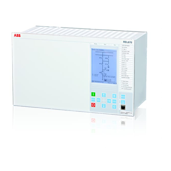
Section 3 1MRK506276-UUS B Overview Section 3 Overview About this chapter This chapter presents a general overview of the Operator's manual. Operator overview The Human machine interface (HMI) on the IED provides an ideal mechanism for the day to day operation and even advanced use of the IED. The keypad, LCD and LEDs on the front of the IED are what constitute the HMI. - Page 24 Section 3 1MRK506276-UUS B Overview The type of IED, the main function type, its serial number, ordering number and production date are found here. Operator's manual...
-
Page 25: Section 4 Understand The Local Human-Machine Interface
Section 4 1MRK506276-UUS B Understand the local human-machine interface Section 4 Understand the local human-machine interface About this chapter This chapter describes the display, its keys (buttons) and LEDs that make up the HMI. How the keys are used to navigate the HMI, how to interpret the graphic information on the LCD and, what the LEDs indicate is explained in the sections that follow. - Page 26 Section 4 1MRK506276-UUS B Understand the local human-machine interface IEC06000531 V1 EN Figure 2: The HMI keypad. Table describes the HMI keys that are used to operate the IED. Table 1: HMI keys on the front of the IED Function Press to close or energize a breaker or disconnector.
-
Page 27: Key Activated Screens
Section 4 1MRK506276-UUS B Understand the local human-machine interface Function Press to navigate forward between screens and move right in editing mode. IEC05000109 V1 EN Press to navigate backwards between screens and move left in editing mode. IEC05000110 V1 EN Press to move up in the single line diagram and in the menu tree. -
Page 28: Lcd
Section 4 1MRK506276-UUS B Understand the local human-machine interface 4.4.1 Medium The following case sizes can be equipped with the medium size LCD: • 1/2 x 19” • 3/4 x 19” • 1/1 x 19” This is a fully graphical monochrome LCD which measures 4.7 x 3.5 inches. It has 28 lines with up to 40 characters per line. -
Page 29: Indication Leds
Section 4 1MRK506276-UUS B Understand the local human-machine interface 4.5.3 Indication LEDs The LED indication module comprising 15 LEDs is standard in 670 series. Its main purpose is to present an immediate visual information for protection indications or alarm signals. Alarm indication LEDs and hardware associated LEDs are located on the right hand side of the front panel. -
Page 30: How To Navigate
Section 4 1MRK506276-UUS B Understand the local human-machine interface How to navigate 4.7.1 Read To read values and access information about the objects being monitored the operator must navigate the menu tree using the arrow keys. The active submenu or value is highlighted. - Page 31 Section 4 1MRK506276-UUS B Understand the local human-machine interface By pressing the L/R key until the uppermost of the two LEDs next to the key lights up, local operator control can be exercised from the HMI. An apparatus is selected using the up and down arrow keys. The active apparatus is highlighted in the display.
-
Page 33: Section 5 Understand The Hmi Tree
• Test • Reset • Authorization • Language Each main menu item can have several other submenus. 5.1.1 Menu-tree for REL670 Main menu Sub menu Sub-sub menu Control Single line diagram Commands Measurements Analog primary values Analog secondary values Analog mean values... - Page 34 Section 5 1MRK506276-UUS B Understand the HMI tree Main menu Sub menu Sub-sub menu General settings Power system Communication Analog modules I/O modules Impedance protection Current protection Voltage protection Control Monitoring Metering Setting group N Differential protection Impedance protection Current protection Voltage protection Frequency protection Multipurpose protection...
-
Page 35: Section 6 Read Measured Values
Section 6 1MRK506276-UUS B Read measured values Section 6 Read measured values About this chapter This chapter describes measurement categories and how to locate them using the HMI. Each measurement category has a section of its own that includes a general description of the type of quantity being measured and the path in the local HMI to the measurement. -
Page 36: View Analog Primary Values
Section 6 1MRK506276-UUS B Read measured values the measurements menu the operator will only see data from the hardware and software installed. View analog primary values 6.2.1 Overview The analog primary values are analog quantities measured on the primary side of the TRM and reflect the actual current or voltage on the primary side of the VTs and CTs. -
Page 37: View Analog Mean Values
Section 6 1MRK506276-UUS B Read measured values Analog secondary values shows secondary CT currents and VT voltages. These are the actual current and voltage values at the TRM inputs. For analog values received from Merging Units, no analog secondary values are shown. Main menu/Measurements/Analog secondary values Displays up to 24 channels with secondary CT and VT data. -
Page 38: View Monitoring Values
Section 6 1MRK506276-UUS B Read measured values View monitoring values 6.5.1 Service values CVMMXU Main menu/Measurement/Monitoring/ServiceValues(MMXU)/SVR Displays up to three instances of CVMMXU with measured values for S, P, Q, PF, U, I, ILead, ILag and F. 6.5.2 Current phasors CMMXU Main menu/Measurement/Monitoring/CurrentPhasors(MMXU)/CP All three phase currents and their phase angles are displayed here. -
Page 39: View Metering Values
Section 6 1MRK506276-UUS B Read measured values The Voltage sequence component displays the positive (V1), negative (V2) and zero (V0) sequence components in the system, and includes the magnitude and phase angle of each component. View metering values 6.6.1 Pulse counter logic PCGGIO Main menu/Measurements/Metering/PulseCounter(PCGGIO)/PC The output data generated from the pulse counter function include data about the status of the counter and counter values. -
Page 41: Section 7 Event List
Section 7 1MRK506276-UUS B Event list Section 7 Event list About this chapter This chapter describes how to find and read the event list. View events 7.1.1 Overview Events displays recorded events such as trips and breaker opened or closed. Main menu/Events Displays a list of events in chronological order and where each event has a time stamp. -
Page 43: Section 8 Handle Disturbances
Section 8 1MRK506276-UUS B Handle disturbances Section 8 Handle disturbances About this chapter This chapter describes disturbance detection and handling. This includes resetting LED alarms, triggering disturbance reports, fault distance calculation and the viewing of several fault indicators. Identify a disturbance A disturbance record can be generated manually by using the Manual Trig functionality in the HMI menu. -
Page 44: View Event Recordings
Section 8 1MRK506276-UUS B Handle disturbances 8.2.3 View event recordings The Event recording section in the Disturbance report shows the recording number. The path in the HMI is shown below. Main menu/Disturbance records/Record xx/Event recording 8.2.4 View trip values In the Trip values section of a disturbance recording both the pre-fault and the fault values for current, voltage and phase angle can be viewed. -
Page 45: Section 9 Read And Change Settings
Section 9 1MRK506276-UUS B Read and change settings Section 9 Read and change settings About this chapter This chapter describes how to find and change settings and parameters. The chapter is divided into two sections which match the way the two categories of settings are divided up in the HMI. -
Page 46: Timesynch
Section 9 1MRK506276-UUS B Read and change settings 9.1.2.2 TimeSynch Main menu/Settings/Time/Synchronization/TimeSynch Here the parameters FineSyncSource, CourseSyncSrc and SyncMaster are switched on or off. 9.1.2.3 TimeSynchBIN Main menu/Settings/Time/Synchronization/TimeSynchBIN Binary input synchronization settings available here are the position of the of the module, the number of the binary input and the detection mode. -
Page 47: General Settings
Section 9 1MRK506276-UUS B Read and change settings General settings Setting group 1 must be selected before making any changes to the parameters in General settings menu. Parameters under General settings that are changed will cause the IED to restart. This occurs automatically and requires no manual intervention. -
Page 48: Remote Communication
Section 9 1MRK506276-UUS B Read and change settings 9.2.2.2 Remote communication Main menu/Settings/General settings/Communication/LDCM configuration/ LDCM Displays settings for Remote Binary Communication (CRB) and for Remote Multi Communication (CRM). The multi communication block can send both binary and analog data whereas the binary can only send binary data. Each instance of CRB has several settable parameters where the channel mode can be set on or off, terminal numbers can be entered, synchronization can be set to master or slave and opto power can be set high or low. -
Page 49: Station Communication
Section 9 1MRK506276-UUS B Read and change settings Main menu/Settings/General settings/Communication/SLM configuration/Rear optical LON port/SPA Settings for SPA over LON are made here. The operation setting is used to switch the function on or off and the slave address setting is where the slave address is entered. Main menu/Settings/General settings/Communication/SLM configuration/Rear optical LON port/Horizontal communication This setting is used to activate or deactivate horizontal communication. -
Page 50: Ethernet Configuration
Section 9 1MRK506276-UUS B Read and change settings Includes available instances of GOOSE binary receive (GB) where setting Operation can be set On or Off. IEC61850–8–1 Main menu/Settings/General settings/Communication/Station communication/ IEC61850–8–1 Includes settings for the IED name, operation (on/off) and GOOSE. Multicommand send Main menu/Settings/General settings/Communication/Station communication/ MultiCommandSend/MT... -
Page 51: Analog And I/O Modules
Section 9 1MRK506276-UUS B Read and change settings Main menu/Settings/General settings/Communication/Ethernet configuration/ Rear OEM-Port AB The IP address, IP mask and Mode for the IEC 61850-8-1 communication using the Optical Ethernet Module (OEM) at the rear of the IED are set here. Main menu/Settings/General settings/Communication/Ethernet configuration/ Rear OEM-Port CD The IP address (with different IP address when a second channel is used), IP mask and... -
Page 52: I/O Modules
Section 9 1MRK506276-UUS B Read and change settings parameters where the type of channel is set, the primary and secondary values from VTs and CTs and for Current Transformers the WYE point location (line side or busbar side) is set. Main menu/Settings/General Settings/Analog modules/MergingUnit Displays parameters for the merging units. -
Page 53: Hmi
Section 9 1MRK506276-UUS B Read and change settings 9.2.4 9.2.4.1 Overview Under HMI in General settings there are submenus for LEDs, Screen, Functions, Reference channel service values and the Change lock function. In the LED submenu there are settings for operation, illumination times, and sequence types for the LEDs on the IED front panel. -
Page 54: Control
Section 9 1MRK506276-UUS B Read and change settings 9.2.5 Control 9.2.5.1 Apparatus control Overview Under Control in General settings, parameters for Apparatus control can be adjusted. These are the parameters for among others Bay control, Switch controller, Reservation input, Circuit breakers and Circuit switches. The parameters include delay times, dependencies, pulse times and characteristics. -
Page 55: Control Commands
Section 9 1MRK506276-UUS B Read and change settings Displays available instances of the local/remote function LocalRemote, LocRemControl that permit the user to set the control mode. Reservation input RESIN Main menu/Settings/General Settings/Control/Apparatus Control/ ReservationInput/RE Displays available instances of the Reservation input function RESIN with one settable parameter per function for future use. -
Page 56: Monitoring
Section 9 1MRK506276-UUS B Read and change settings 9.2.6 Monitoring 9.2.6.1 Overview Under monitoring there are parameters for setting Service values, current phasors, Voltage phasors, Disturbance reports, Fault locator and the Measured value expander block. 9.2.6.2 Service values CVMMXU Main menu/Settings/General Settings/Monitoring/ServiceValues(MMXN)/SVR Displays available instances of CVMMXU. -
Page 57: Generic Measured Value Mvggio
Section 9 1MRK506276-UUS B Read and change settings 9.2.6.5 Generic measured value MVGGIO Main menu/Settings/General Settings/Monitoring/GenericMeasuredValue(GGIO)/ Displays available instances of settings for the Measured value function MVGGIO with a number of settable parameters. These settings are used to define the range of values used in the function block and to set the threshold values. -
Page 58: Pulse Counter Logic Pcggio
Section 9 1MRK506276-UUS B Read and change settings 9.2.7.2 Pulse counter logic PCGGIO Main menu/Settings/General settings/Metering/PulseCounter(PCGGIO)/PC In the Pulse counter PCGGIO folder there are a number of instances of the pulse counter function PCGGIO. Each instance has a setting and some settable parameters. The setting Operation is used to turn the function on or off. -
Page 59: Impedance Protection
Section 9 1MRK506276-UUS B Read and change settings Displays available instances of HZPDIF (87X) with settings for operation, the alarm voltage level [V] on the CT secondary side, the time delay to activate the alarm, the operating voltage level [V] on the secondary side of the CT and the value of the series resistor in [Ω]. -
Page 60: Fullscheme Distance Protection, Quadrilateral For Earth Faults Zmmpdis, Zmmapdis (21)
Section 9 1MRK506276-UUS B Read and change settings Displays available adjustable parameters. These include the ohm per phase for resistive and reactive reach as well as the ohm per loop for phase to phase, and phase to ground fault resistance. Zones can also be set on or off. 9.3.3.5 Fullscheme distance protection, quadrilateral for earth faults ZMMPDIS, ZMMAPDIS (21) -
Page 61: Directional Impedance Element For Mho Characteristics Zdmrdir (21D)
Section 9 1MRK506276-UUS B Read and change settings Includes settings for base current, voltage and impedance direction angles. 9.3.3.10 Directional impedance element for mho characteristics ZDMRDIR (21D) Main menu/Settings/Setting group N/Impedance protection/Directional Impedance/ZDM Includes settings for base current, voltage and impedance direction angles. 9.3.3.11 Directional impedance quadrilateral, including series compensation ZDSRDIR (21D) -
Page 62: Power Swing Detection Zmrpsb (78)
Section 9 1MRK506276-UUS B Read and change settings Measurement mode, impedance settings and other pole slip protection parameters are found here. 9.3.3.16 Power swing detection ZMRPSB (78) Main menu/Settings/Setting Group N/Impedance protection/ PowerSwingDetection(RPSB,78))/PSD Includes settings for operation, reactive and resistive boundaries, various timers, base settings for current levels and several others. -
Page 63: Directional Over-Power Protection Goppdop (32)
Section 9 1MRK506276-UUS B Read and change settings Includes current and timer settings. 9.3.4.4 Directional over-power protection GOPPDOP (32) Main menu/Settings/Setting Group N/Current protection/ DirOverPowerProtection(PDOP,32)/GOP Includes power, angle and calibration factor settings. 9.3.4.5 Directional under-power protection GUPPDUP (37) Main menu/Settings/Setting Group N/Current protection/ DirUnderPowerProtection(PDUP,37)/GUP Includes power, angle and calibration factor settings. -
Page 64: Pole Discrepancy Protection Ccrpld (52Pd)
Section 9 1MRK506276-UUS B Read and change settings 9.3.4.9 Pole discrepancy protection CCRPLD (52PD) Main menu/Settings/Setting Group N/Current protection/PoleDiscordance(RPLD, 52PD)/PD Displays instances of CCRPLD (52PD) with some settings per instance. The settings are for operation, base current, trip time delay, contact function selection, current function selection, asymmetrical magnitude of current and current release threshold. -
Page 65: Voltage Protection
Section 9 1MRK506276-UUS B Read and change settings 9.3.5 Voltage protection 9.3.5.1 Overview For Voltage protection there are settings for Under-voltage, Over-voltage, Residual over- voltage and Overexcitation protection. There are three instances of parameters in each category except in the case of Overexcitation which has two instances. Each instance consists of a number of parameters that make it possible to switch the function On or Off, set rated quantities or make other adjustments necessary for the fine tuning of the function itself. -
Page 66: Two Step Undervoltage Protection Uv2Ptuv (27)
Section 9 1MRK506276-UUS B Read and change settings 9.3.5.6 Two step undervoltage protection UV2PTUV (27) Main menu/Settings/Setting Group N/Voltage protection/ UnderVoltage2Step(PTUV,27)/TUV Displays available settable parameters. The operation mode, the operate voltage as percentage of UbaseVbase are examples of the settings available here. 9.3.5.7 Voltage differential protection VDCPTOV (60) Main menu/Settings/Setting Group N/Voltage protection/VoltageDiff(PTOV,60)/... -
Page 67: Underfrequency Protection Saptuf (81)
Section 9 1MRK506276-UUS B Read and change settings 9.3.6.4 Underfrequency protection SAPTUF (81) Main menu/Settings/Setting Group N/Frequency protection/ Underfrequency(PTUF,81)/TUF Displays available instances of SAPTUF (81) with a number of settings per instance. These include parameters like operation, base voltage, and pickup frequency. To ensure the proper operation of the Underfrequency function the Operation setting must be On. -
Page 68: Phase Segregated Scheme Communication Logic For Distance Protection Zc1Ppsch (85)
Section 9 1MRK506276-UUS B Read and change settings Displays available settable parameters which include scheme type, coordination time for blocking coordination scheme, minimum duration of a carrier send signal and security timer for loss of carrier guard detection. 9.3.8.3 Phase segregated scheme communication logic for distance protection ZC1PPSCH (85) Main menu/Settings/Setting Group N/Scheme communication/ ZPhSegSchComm(PSCH,85)/ZC1P... -
Page 69: Local Acceleration Logic Zclcplal
Section 9 1MRK506276-UUS B Read and change settings 9.3.8.8 Local acceleration logic ZCLCPLAL Main menu/Settings/Setting group N/Scheme communication/Local AccelerationLogic(PLAL)/ZCLC Displays available settable parameters for setting OperationOn or Off, setting time delays, enable and disable various functions. 9.3.9 Secondary system supervision 9.3.9.1 Overview Under Secondary circuit supervision there are settings for Current circuit supervision... -
Page 70: Autorecloser Smbrrec (79)
Section 9 1MRK506276-UUS B Read and change settings circuit breakers. The autorecloser settings include the number of shots, first shot combinations and many other useful settings. 9.3.10.2 Autorecloser SMBRREC (79) Main menu/Settings/Setting Group N/Control/AutoRecloser(RREC,79)/AR Displays available instances of the autorecloser function SMBRREC (79) with several settable parameters per instance. -
Page 71: Logic
Section 9 1MRK506276-UUS B Read and change settings 9.3.12 Logic 9.3.12.1 Overview Under Logic there are settings for Trip logic, Trip matrix, Logic gate, Logic SR memory and Logic timer set. Under each of these function categories there are a number of instances, each with a parameter set. -
Page 72: Activate Setting Group
Section 9 1MRK506276-UUS B Read and change settings Activate setting group Main menu/Settings/Activate setting group Available setting groups can be configured in PCM600. Under activate setting group one of these setting groups can be chosen for the application at hand. Language Under the language part of the main menu the language options available in the HMI are located. -
Page 73: Section 10 Diagnose Ied Status
Section 10 1MRK506276-UUS B Diagnose IED status Section 10 Diagnose IED status About this chapter This chapter describes where in the HMI tree to find the cause of an internal IED failure and information about the IED as such. 10.1 Read internal events Main menu/Diagnostics/Internal events Internal events in the diagnostics menu of the HMI tree shows a time stamped list of... - Page 74 Section 10 1MRK506276-UUS B Diagnose IED status Main menu/Diagnostics/IED status/Merging units/MergingUnit:x The list includes all the status signals of each merging unit. Main menu/ Diagnostics/Communication/Front port Displays various communication status signals for front port communication. Main menu/ Diagnostics/Communication/Rear OEM - port AB Displays various communication status signals for rear AB port communication.
-
Page 75: Section 11 Test The Ied
Section 11 1MRK506276-UUS B Test the IED Section 11 Test the IED About this chapter This chapter describes the tests that can be performed in the test section of the HMI. 11.1 Overview The test part of the tree view in the HMI has a number of submenus for test and viewing activities. -
Page 76: Ied Test Mode
Section 11 1MRK506276-UUS B Test the IED Control displays the Synchronism-checkAutorecloser, and Apparatus control functions. The Synchronism-checkand the Autorecloser functions include a number of function related measurements such as calculated differences of measurements and number and kind of reclosing attempts. Apparatus control includes up to 19 functions each with their own set of measurement data regarding interlocking, breaker and isolator conditions. -
Page 77: Binary Input Module Bim
Section 11 1MRK506276-UUS B Test the IED 11.3.1.1 Binary Input Module BIM Main menu/Test/Binary input values/Binary input modules Displays available binary input modules with several binary values per module. 11.3.1.2 Signal matrix for binary input SMBI Main menu/Test/Binary Input Values/SMT binary inputs/Instance:x Displays available instances of SMT binary inputs with several inputs per instance. -
Page 78: Differential Protection
Section 11 1MRK506276-UUS B Test the IED 11.5.2 Differential protection Main menu/Test/Function test modes/Differential protection Test of the high impedance restricted ground fault protection. 11.5.3 Impedance protection Main menu/Test/Function test mode/Impedance protection Test of switch onto fault logic, distance protection zones one to five, local acceleration logic, power swing detection and phase selection with load encroachment. -
Page 79: Secondary System Protection
Section 11 1MRK506276-UUS B Test the IED Test of scheme communication logic, for residual overcurrent protection and distance protection, as well as current reversal and weak end infeed logic, for distance protection and residual overcurrent protection. 11.5.9 Secondary system protection Main menu/Test/Function test modes/Secondary system supervision Test of current circuit supervision and fuse failure supervision. -
Page 80: Differential Protection
Section 11 1MRK506276-UUS B Test the IED 11.6.2 Differential protection 11.6.2.1 High impedance differential protection HZPDIF (87) Main menu/Test/Function status/Differential protection/ HighImpDifferential(PDIF,87)/HZD Displays available instances of HZPDIF (87) with some measurements per instance. These are the trip signal, the alarm signal and the measured RMS voltage on the secondary side of the CT. -
Page 81: Fullscheme Distance Protection, Quadrilateral For Earth Faults Zmmpdis, Zmmapdis (21)
Section 11 1MRK506276-UUS B Test the IED Displays instances of ZMCPDIS (21). Main menu/Test/Function status/Impedance Protection/DistanceZones(PDIS,21)/ Displays instances of ZMCAPDIS (21). 11.6.3.4 Fullscheme distance protection, quadrilateral for earth faults ZMMPDIS, ZMMAPDIS (21) Main menu/Test/Function status/Impedance protection/QadEarthDistance(PDIS, 21)/ZMM Displays the output data of ZMMPDIS (21) for zone 1. Main menu/Test/Function status/Impedance protection/QadEarthDistance(PDIS, 21)/ZMM Displays the output data of ZMMAPDIS (21)for zone 2-5. -
Page 82: Directional Impedance Zdrdir (21D)
Section 11 1MRK506276-UUS B Test the IED 11.6.3.8 Directional impedance ZDRDIR (21D) Main menu/Test/Function status/Impedance protection/ DirectionalImpedance(RDIR)/ZD Displays one instance of ZDRDIR (21D) showing one measurement indicating the status of pickup signals. 11.6.3.9 Directional impedance element for mho characteristic ZDMRDIR (21D) Main menu/Test/Function status/Impedance Protection/ DirectionalImpedance(RDIR,21D)/ZDM Displays instances of ZDMRDIR (21D). -
Page 83: Power Swing Detection Zmrpsb (78)
Section 11 1MRK506276-UUS B Test the IED 11.6.3.14 Power swing detection ZMRPSB (78) Main menu/Test/Function status/Impedance protection/ PowerSwingDetection(RPSB,78)/PSD1 Displays one instance of ZMRPSB (78) with three measurements. These indicate a power swing and show the measured impedances for the inner and outer impedance boundaries. -
Page 84: Directional Under-Power Protection Guppdup (37)
Section 11 1MRK506276-UUS B Test the IED 11.6.4.4 Directional under-power protection GUPPDUP (37) Main menu/Test/Function status/Current protection/ DirUnderPowerProtection(PDUP,37)/GUP Displays the output data of GUPPDUP (37). 11.6.4.5 Instantaneous phase overcurrent protection PHPIOC (50) Main menu/Test/Function status/Current protection/ InstPhaseOverCurrent(PIOC,50)/IOC1 Displays available instances of PHPIOC (50) with a number of measurements per instance showing the trip status in general and per phase. -
Page 85: Sensitive Directional Residual Over Current And Power Protection Sdepsde (67N)
Section 11 1MRK506276-UUS B Test the IED Displays available instances of EF4PTOC (51N,67N) with a number of measurements per instance. The measurements indicate trip and pickup signal status as well as the 2nd harmonic block signal status. 11.6.4.10 Sensitive directional residual over current and power protection SDEPSDE (67N) Main menu/Test/Function status/Current protection/SensDirResOvCurr(PSDE, 67N)/SDE... -
Page 86: Two Step Overvoltage Protection Ov2Ptov (59)
Section 11 1MRK506276-UUS B Test the IED Displays available instances of OEXPVPH (24) with a number of measurements per instance. These measurements indicate whether values are out of the measuring range (ERROR) and if the overexcitation function has caused a trip (TRIP). The thermal status as a percentage of the trip level and the calculated time to trip are among the other outputs available here. -
Page 87: Rate-Of-Change Frequency Protection Sapfrc (81)
Section 11 1MRK506276-UUS B Test the IED Displays available instances of SAPTOF (81) with some measurements per instance consisting of trip and pickup signal status. The pickup duration as percentage of the total trip time and a blocking indication as a result of low voltage. 11.6.6.2 Rate-of-change frequency protection SAPFRC (81) Main menu/Test/Function status/Frequency protection/... -
Page 88: Scheme Communication
Section 11 1MRK506276-UUS B Test the IED 11.6.8 Scheme communication Scheme communication functions which are used in conjunction with distance protection generate viewable data about the signals used in these applications. Depending on the options chosen, data about weak end infeed, ground faults etc. is sent to and from IEDs. -
Page 89: Scheme Communication Logic For Residual Overcurrent Protection Ecpsch (85)
Section 11 1MRK506276-UUS B Test the IED Displays one instance of ECRWPSCH (85) with four measurements per instance. 11.6.8.6 Scheme communication logic for residual overcurrent protection ECPSCH (85) Main menu/Test/Function status/Scheme communication/ EFSchemeCommunication(PSCH,85)/EFC Displays available instances of ECPSCH (85) with some measurements indicating carrier and trip status. - Page 90 Section 11 1MRK506276-UUS B Test the IED Displays available instances of the function with an open and a close parameter for each disconnection device. The enable open (EN_OPEN) parameter will have the output value one if an open operation is allowed and a zero output if an open operation is not allowed.
- Page 91 Section 11 1MRK506276-UUS B Test the IED Interlock, one and a half circuit breaker-and-a-half line A Main menu/Test/Function status/Control/Apparatus control/Interl11½CBLineA/ Displays available measurements per breaker arrangement (instances of IL). The measurements show the states of the various disconnectors, breakers and grounding switches.
- Page 92 Section 11 1MRK506276-UUS B Test the IED Displays available instances of the function IF with several boolean outputs per instance. These indicate for which disconnect devices closing and switching of is allowed and also indicate the status and validity of devices. For example, the measurement named 1289OPTR indicates whether or not 189 and 289 are in the open position.
-
Page 93: Autorecloser Smbrrec (79)
Section 11 1MRK506276-UUS B Test the IED counter (CNT_VAL), the latest value of the error indication during command (L_CAUSE) and error indication during command (CAUSE) which have integer outputs, the measurement outputs have boolean values indicating the status of processes and devices. Bay reserve QCRSV Main menu/Test/Function status/Control/Apparatus control/BayReserve(CRSV)/ Displays available instances of the function QCRSV with several measurements per... -
Page 94: Commands
Section 11 1MRK506276-UUS B Test the IED 11.6.10.3 Commands In the commands menu it is possible to view three sets of values. These are found under the submenus menucascade/uicontrol. Automation bits, command function for DNP3.0 AutomationBits Main menu/Test/Function status/Control/Commands/Automation Bits/ABI Displays the output data of the AutomationBits function. -
Page 95: Monitoring
Section 11 1MRK506276-UUS B Test the IED Displays available instances of SESRSYN (25) with a number of measurements per instance. These include information about which lines and buses selected, various voltage and frequency differences and feedback on synchronization status. 11.6.11 Monitoring Monitoring includes large amounts of viewable data including Disturbance report data, Service values, Current phasors, Voltage phasors, Milliampere signal level supervision,... -
Page 96: Global Positioning System
Section 11 1MRK506276-UUS B Test the IED Main menu/Test/Function status/Monitoring/GenericMeasuredValue(GGIO)/MV Displays the analog output from the MVGGIO block. The value shown here depends on the settings and the logical configuration of the preprocessing blocks. The measurement displayed may be current, voltage, frequency, phase angle etc. 11.6.11.6 Global positioning system Main menu/Test/Function status/Monitoring/GPS... -
Page 97: Logic
Section 11 1MRK506276-UUS B Test the IED 11.6.12 Logic Under the Logic function folder there is viewable data for trip logic (showing number of poles that have tripped and trip signal information), event counter values, Logic gate outputs, Logic SR memory output states and Logic timer set output states are also shown here. -
Page 98: Logic Sr/Rs Memory
Section 11 1MRK506276-UUS B Test the IED Displays available instances of the gate output. The output data type is an integer with a possible value from 0 to 255. 11.6.12.6 Logic SR/RS memory Main memory/Test/Function status/Logic/LogicSRMemory/SM Displays available instances of the function SM. The output data presented in the HMI is boolean and indicates whether or not a signal is present. -
Page 99: Setting Groups
Section 11 1MRK506276-UUS B Test the IED The MultiCommand Send indication is used to display data from the Local Optical network (LON). MultiCommand receive Main menu/Test/Function status/Communication/Station communication/ MultipleCommandReceive/CM The MultiCommand Receive indications displayed here show available sets of output data. -
Page 100: Led Test
Section 11 1MRK506276-UUS B Test the IED 11.7 LED Test Main menu/Test/LED test The Test LEDs menu enables the operator to activate LEDs manually. LEDs that do not light up are defective. Defective LEDs are also logged in Disturbance records under Monitoring. -
Page 101: Section 12 Control And Supervise The Bay
Section 12 1MRK506276-UUS B Control and supervise the bay Section 12 Control and supervise the bay About this chapter This chapter describes the various control and supervision functions available in the HMI. In particular, how the single line diagram available on the display can be used for this purpose. -
Page 102: Locating And Using The Single Line Diagram
Section 12 1MRK506276-UUS B Control and supervise the bay 12.1.2 Locating and using the single line diagram It is possible to navigate the SLD screen using the up and down keys on the IED keypad. The apparatus under control is highlighted as the user moves from symbol to symbol using the keypad. -
Page 103: Control Screen Messages
Section 12 1MRK506276-UUS B Control and supervise the bay Symbol Description Disconnector xx05000238.vsd IEC05000238 V1 EN Junction xx05000240.vsd IEC05000240 V1 EN Motor xx05000241_ansi.vsd ANSI05000241 V1 EN Reactor xx05000242_ansi.vsd ANSI05000242 V1 EN Surge arrestor xx05000243_ansi.vsd ANSI05000243 V1 EN Trafo 2 windings xx05000244_ansi.vsd ANSI05000244 V1 EN Trafo 3 windings... -
Page 105: Section 13 Reset
Section 13 1MRK506276-UUS B Reset Section 13 Reset About this chapter This chapter describes how to reset the IED and when this is necessary. 13.1 Reset guide 13.1.1 Reset counters 13.1.1.1 Reset autorecloser SMBRREC (79) The recorded number of reclosings are reset under Reset counters in the HMI tree. Main menu/Reset/Reset counters/Autorecloser(RREC,79)/AR In the dialog box that appears, choose YES to reset. -
Page 106: Reset Pulse Counter Pcggio
Section 13 1MRK506276-UUS B Reset 13.1.1.5 Reset pulse counter PCGGIO The Pulse counter is reset under Reset counters menu in the HMI tree. Main menu/Reset/Reset counters/PulseCounter(GGIO)/PC In the dialog box that appears, choose YES to reset. 13.1.1.6 LDCM clear counters Main menu/Reset/Reset counters/LDCMCommunication/LDCMX Activating Reset of LDCM counters sets the counter concerned to zero. -
Page 107: All Indication Leds
Section 13 1MRK506276-UUS B Reset 13.1.3.2 All indication LEDs Activating the Reset of indication LEDs will zero all fifteen LEDs to the right of the LCD. Main mnenu/Reset/Reset LEDs/All indication LEDs In the dialog box that appears, choose YES to reset. 13.1.4 Reset lockout SMPPTRC (94) Objects that are considered at risk after a trip may be prevented from reconnecting by a... -
Page 109: Section 14 Authorization
Section 14 1MRK506276-UUS B Authorization Section 14 Authorization About this chapter This chapter describes password procedures and levels of access in the system. 14.1 Overview To safeguard the interests of our customers, both the IED and the tools that are accessing the IED are protected, subject of authorization handling. -
Page 110: Authorization Handling In The Ied
Section 14 1MRK506276-UUS B Authorization Main menu/Authorization 14.3 Authorization handling in the IED At delivery the default user is the SuperUser. No Log on is required to operate the IED until a user has been created with the User Management Tool. If there is no user created, an attempt to log on will display a message box: “No user defined!”... -
Page 111: Section 15 Glossary
Section 15 1MRK506276-UUS B Glossary Section 15 Glossary About this chapter This chapter contains a glossary with terms, acronyms and abbreviations used in ABB technical documentation. Alternating current Application configuration tool within PCM600 A/D converter Analog to digital converter ADBS... - Page 112 Section 15 1MRK506276-UUS B Glossary COMTRADE Standard Common Format for Transient Data Exchange format for Disturbance recorder according to IEEE/ANSI C37.111, 1999 / IEC60255-24 Contra-directional Way of transmitting G.703 over a balanced line. Involves four twisted pairs of with two are used for transmitting data in both directions, and two pairs for transmitting clock signals Central processor unit Carrier receive...
- Page 113 Section 15 1MRK506276-UUS B Glossary Electrostatic discharge FOX 20 Modular 20 channel telecommunication system for speech, data and protection signals FOX 512/515 Access multiplexer FOX 6Plus Compact, time-division multiplexer for the transmission of up to seven duplex channels of digital data over optical fibers G.703 Electrical and functional description for digital lines used by local telephone companies.
- Page 114 Section 15 1MRK506276-UUS B Glossary specifications from the PCI SIG (Special Interest Group) for the electrical EMF Electro Motive Force. Intelligent electronic device I-GIS Intelligent gas insulated switchgear Instance When several occurrences of the same function are available in the IED they are referred to as instances of that function. One instance of a function is identical to another of the same kind but will have a different number in the IED user interfaces.
- Page 115 Section 15 1MRK506276-UUS B Glossary National Control Centre OCO cycle Open-close-open cycle Overcurrent protection OLTC On load tap changer Over voltage Overreach A term used to describe how the relay behaves during a fault condition. For example a distance relay is over-reaching when the impedance presented to it is smaller than the apparent impedance to the fault applied to the balance point, i.e.
- Page 116 Section 15 1MRK506276-UUS B Glossary Real time clock Remote terminal unit Substation Automation Switch or push-button to close Station control system System configuration tool according to standard IEC 61850 SMA connector Subminiature version A, A threaded connector with constant impedance. Signal matrix tool within PCM600 Station monitoring system SNTP...
- Page 117 Section 15 1MRK506276-UUS B Glossary Underreach A term used to describe how the relay behaves during a fault condition. For example a distance relay is under-reaching when the impedance presented to it is greater than the apparent impedance to the fault applied to the balance point, i.e. the set reach.
- Page 120 ABB Inc. 3450 Harvester Road Burlington, ON L7N 3W5, Canada Phone Toll Free: 1-800-HELP-365, menu option #8 ABB Mexico S.A. de C.V. Paseo de las Americas No. 31 Lomas Verdes 3a secc. 53125, Naucalpan, Estado De Mexico, MEXICO Phone (+1) 440-585-7804, menu...