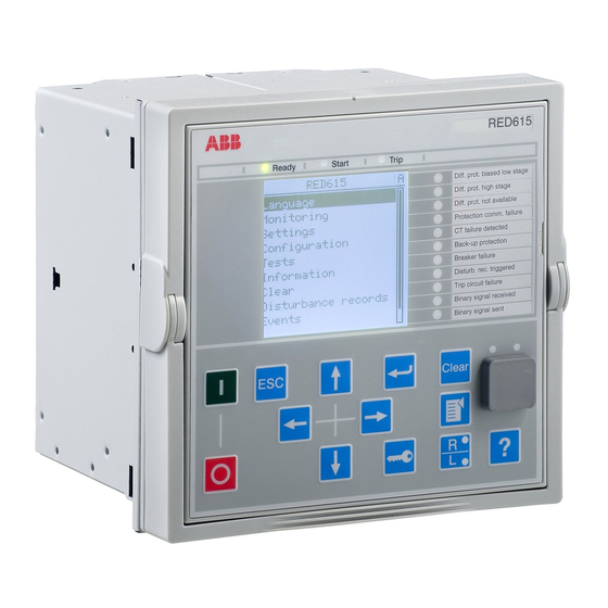
ABB RED615 Product Manual
Line differential protection and control
Hide thumbs
Also See for RED615:
- Technical manual (896 pages) ,
- Operation manual (116 pages) ,
- Applications manual (116 pages)
Table of Contents
Advertisement
Quick Links
Advertisement
Table of Contents

Related Manuals for ABB RED615


Summary of Contents for ABB RED615
- Page 1 ® Relion 615 series Line Differential Protection and Control RED615 Product Guide...
-
Page 2: Table Of Contents
30. Document revision history...........63 Disclaimer The information in this document is subject to change without notice and should not be construed as a commitment by ABB. ABB assumes no responsibility for any errors that may appear in this document. © Copyright 2012 ABB. -
Page 3: Description
IEC 61850 optic link or a galvanic pilot wire connection. with GOOSE messaging, IEC 60870-5-103, ® RED615 is a member of ABB’s Relion product ® Modbus and DNP3. family and part of its 615 protection and control product series. - Page 4 Line Differential Protection and Control 1MRS756500 F RED615 Product version: 4.0 Table 2. Supported functions Functionality Protection Three-phase non-directional overcurrent protection, low stage, instance 1 ● ● ● Three-phase non-directional overcurrent protection, high stage, instance 1 ● ● ● Three-phase non-directional overcurrent protection, high stage, instance 2 ●...
- Page 5 Line Differential Protection and Control 1MRS756500 F RED615 Product version: 4.0 Table 2. Supported functions, continued Functionality Master trip, instance 1 ● ● ● Master trip, instance 2 ● ● ● Control Circuit-breaker control ● ● ● Disconnector control, instance 1 ●...
-
Page 6: Protection Functions
Line Differential Protection and Control 1MRS756500 F RED615 Product version: 4.0 3. Protection functions The line differential protection function includes a The IED offers two-stage phase-segregated line stabilized low stage and an instantaneous high differential protection, phase overcurrent stage. The stabilized low stage provides sensitive... - Page 7 Line Differential Protection and Control 1MRS756500 F RED615 Product version: 4.0 GUID-81A76312-4CC1-4AE8-A0A3-14C9800EE0E2 V3 EN Figure 2. Protection function overview of standard configuration B...
-
Page 8: Application
Protection function overview of standard configuration C 4. Application Combining horizontal GOOSE communication RED615 can be used in a variety of applications over a station bus and binary signal transfer over requiring an absolutely selective unit type the protection communication link offers new protection system. - Page 9 GUID-D4440C4D-6C02-4A37-A38B-1AEDCA9246FC V1 EN Figure 4. Closed loop network configuration with RED615 line differential protection and control IEDs Under certain operational circumstances, such as the protection devices of the network when the maintenance of primary equipment or substation...
- Page 10 Line Differential Protection and Control 1MRS756500 F RED615 Product version: 4.0 GUID-245166BA-1052-4EDC-8C2D-9C968FA05C66 V3 EN Figure 5. RED615 protecting an interconnecting feeder between two primary distribution substations...
- Page 11 Line Differential Protection and Control 1MRS756500 F RED615 Product version: 4.0 GUID-9DC3BAB9-9FA4-4A6D-83C4-E1A7FCE811B0 V3 EN Figure 6. Line differential protection of an overhead line feeder using RED615 with the standard configuration B...
- Page 12 Line Differential Protection and Control 1MRS756500 F RED615 Product version: 4.0 figure 6 selectivity of earth-fault protection is tripping of the circuit breaker. If the earth-fault is ensured using binary signal transfer (BST) within the protected zone, no blocking signal will...
- Page 13 Line Differential Protection and Control 1MRS756500 F RED615 Product version: 4.0 GUID-9EFBFF56-5045-4B24-9C29-01C98ABA81A1 V3 EN Figure 7. Line differential protection of an overhead line feeder using RED615 with the standard configuration C and auto-reclosing option.
-
Page 14: Supported Abb Solutions
The upper circuit breaker is 5. Supported ABB solutions substation level functionality. COM600 features a ABB’s 615 series protection and control IEDs web-browser based HMI providing a together with the Grid Automation controller customizable graphical display for visualizing... -
Page 15: Control
System 800xA 6. Control circuit-breaker control the IED features two RED615 integrates functionality for the control of control blocks which are intended for motor- a circuit breaker via the front panel HMI or by operated control of disconnectors or circuit means of remote controls. -
Page 16: Measurement
IED for each inputs and binary outputs freely available per controllable primary device taken into use. standard configuration in RED615 is listed in the Depending on the chosen standard configuration table below. Table 4. Number of controllable objects in addition to CB... -
Page 17: Disturbance Recorder
Line Differential Protection and Control 1MRS756500 F RED615 Product version: 4.0 8. Disturbance recorder The available measurement modes include DFT, The IED is provided with a disturbance recorder RMS and peak-to-peak. In addition, the maximum featuring up to 12 analog and 64 binary signal demand current with time stamp is separately channels. -
Page 18: Protection Communication And Supervision
The protection communication supervision communication, RED615 IEDs in combination continuously monitors the protection with RPW600 communication modems offer a communication link. The IED immediately blocks modern phase-segregated line differential the line differential protection function in case that protection solution over existing pilot wire cables. -
Page 19: Access Control
Line Differential Protection and Control 1MRS756500 F RED615 Product version: 4.0 RED615 RED615 Fibre-optic line differential communication link Protection communication and supervision Binary signal transfer GUID-8CE71CC9-F0EA-4BE9-B693-173CAEA9FA58 V1 EN Figure 10. Fibre-optic protection communication link RED615 RED615 RPW600 Pilot wire line differential... -
Page 20: Station Communication
Line Differential Protection and Control 1MRS756500 F RED615 Product version: 4.0 All binary inputs and outputs contacts are freely Please refer to the Input/output overview table configurable with the signal matrix or application and the terminal diagrams for more detailed configuration functionality of PCM600. - Page 21 Line Differential Protection and Control 1MRS756500 F RED615 Product version: 4.0 Modbus implementation supports RTU, ASCII and The IED supports the following time TCP modes. Besides standard Modbus synchronization methods with a time-stamping functionality, the IED supports retrieval of time-...
- Page 22 Line Differential Protection and Control 1MRS756500 F RED615 Product version: 4.0 Client A Client B Network Network Managed Ethernet switch Managed Ethernet switch with RSTP support with RSTP support REU615 REM615 RED615 REF615 RET615 GUID-AB81C355-EF5D-4658-8AE0-01DC076E519C V3 EN Figure 12. Self-healing Ethernet ring solution Table 6.
-
Page 23: Technical Data
Line Differential Protection and Control 1MRS756500 F RED615 Product version: 4.0 19. Technical data Table 7. Dimensions Description Value Width frame 177 mm case 164 mm Height frame 177 mm (4U) case 160 mm Depth 201 mm (153 + 48 mm) - Page 24 Line Differential Protection and Control 1MRS756500 F RED615 Product version: 4.0 Table 9. Energizing inputs Description Value Rated frequency 50/60 Hz Current inputs Rated current, I 1/5 A Thermal withstand capability: • Continuously 20 A • For 1 s 100 A...
- Page 25 Line Differential Protection and Control 1MRS756500 F RED615 Product version: 4.0 Table 12. Signal outputs and IRF output Description Value Rated voltage 250 V AC/DC Continuous contact carry Make and carry for 3.0 s 10 A Make and carry 0.5 s...
- Page 26 20 km < 8 dB SM 9/125 μm Maximum allowed attenuation caused by connectors and cable altogether Use single-mode fibre with recommended minimum length of 3 m to connect RED615 to the pilot wire modem RPW600. Table 17. IRIG-B Description Value...
- Page 27 Line Differential Protection and Control 1MRS756500 F RED615 Product version: 4.0 Table 20. Environmental tests Description Type test value Reference Dry heat test • 96 h at +55ºC IEC 60068-2-2 • 16 h at +70ºC Dry cold test • 96 h at -25ºC IEC 60068-2-1 •...
- Page 28 Line Differential Protection and Control 1MRS756500 F RED615 Product version: 4.0 Table 21. Electromagnetic compatibility tests Description Type test value Reference 1 MHz/100 kHz burst disturbance IEC 61000-4-18 test: IEC 60255-22-1, class III IEEE C37.90.1-2002 • Common mode 2.5 kV •...
- Page 29 Line Differential Protection and Control 1MRS756500 F RED615 Product version: 4.0 Table 21. Electromagnetic compatibility tests, continued Description Type test value Reference Voltage dips and short interruptions: 30%/10 ms IEC 61000-4-11 60%/100 ms 60%/1000 ms >95%/5000 ms Power frequency immunity test:...
- Page 30 Line Differential Protection and Control 1MRS756500 F RED615 Product version: 4.0 Table 24. Product safety Description Reference LV directive 2006/95/EC Standard EN 60255-27 (2005) EN 60255-1 (2009) Table 25. EMC compliance Description Reference EMC directive 2004/108/EC Standard EN 50263 (2000) EN 60255-26 (2007) Table 26.
- Page 31 Line Differential Protection and Control 1MRS756500 F RED615 Product version: 4.0 Protection functions Table 27. Line differential protection (LNPLDF) Characteristics Value Depending on the frequency of the current measured: f Operation accuracy ±2 Hz Low stage ±2.5% of the set value High stage ±2.5% of the set value...
- Page 32 Line Differential Protection and Control 1MRS756500 F RED615 Product version: 4.0 Table 29. Binary signal transfer (BSTGGIO) Characteristic Value Fiber optic link < 5 ms Galvanic pilot wire Signalling delay link < 10 ms Table 30. Three-phase non-directional overcurrent protection (PHxPTOC)
- Page 33 Line Differential Protection and Control 1MRS756500 F RED615 Product version: 4.0 Table 31. Three-phase non-directional overcurrent protection (PHxPTOC) main settings Parameter Function Value (Range) Step Start Value PHLPTOC 0.05...5.00 x I 0.01 PHHPTOC 0.10...40.00 x I 0.01 PHIPTOC 1.00...40.00 x I 0.01...
- Page 34 Line Differential Protection and Control 1MRS756500 F RED615 Product version: 4.0 Table 32. Non-directional earth-fault protection (EFxPTOC) Characteristic Value Operation accuracy Depending on the frequency of the current measured: f ±2 Hz EFLPTOC ±1.5% of the set value or ±0.002 x I EFHPTOC ±1.5% of set value or ±0.002 x I...
- Page 35 Line Differential Protection and Control 1MRS756500 F RED615 Product version: 4.0 Table 33. Non-directional earth-fault protection (EFxPTOC) main settings Parameter Function Value (Range) Step Start value EFLPTOC 0.010...5.000 x I 0.005 EFHPTOC 0.10...40.00 x I 0.01 EFIPTOC 1.00...40.00 x I 0.01...
- Page 36 Line Differential Protection and Control 1MRS756500 F RED615 Product version: 4.0 Table 34. Directional earth-fault protection (DEFxPDEF) Characteristic Value Operation accuracy Depending on the frequency of the current measured: f ±2 Hz DEFLPDEF Current: ±1.5% of the set value or ±0.002 x I Voltage ±1.5% of the set value or ±0.002 x U...
- Page 37 Line Differential Protection and Control 1MRS756500 F RED615 Product version: 4.0 Table 35. Directional earth-fault protection (DEFxPDEF) main settings Parameter Function Value (Range) Step Start Value DEFLPDEF 0.010...5.000 x I 0.005 DEFHPDEF 0.10...40.00 x I 0.01 Directional mode DEFLPDEF and...
- Page 38 Line Differential Protection and Control 1MRS756500 F RED615 Product version: 4.0 Table 37. Transient/intermittent earth-fault protection (INTRPTEF) main settings Parameter Function Value (Range) Step Directional mode INTRPTEF 1=Non-directional 2=Forward 3=Reverse Operate delay time INTRPTEF 40...1200000 ms Voltage start value (voltage INTRPTEF 0.01...0.50 x Un...
- Page 39 Line Differential Protection and Control 1MRS756500 F RED615 Product version: 4.0 Table 39. Admittance-based earth-fault protection (EFPADM) main settings Parameter Values (Range) Unit Step Default Description Voltage start value 0.05...5.00 0.01 0.05 Voltage start value Directional mode 1=Non-directional 2=Forward Directional mode...
- Page 40 Line Differential Protection and Control 1MRS756500 F RED615 Product version: 4.0 Table 40. Wattmetric based earth-fault protection (WPWDE) Characteristic Value Operation accuracy Depending on the frequency of the current measured: fn ±2 Hz Current and voltage: ±1.5 % of the set value or ±0.002 x In Power: ±3 % of the set value or ±0.002 x Pn...
- Page 41 Line Differential Protection and Control 1MRS756500 F RED615 Product version: 4.0 Table 42. Harmonics earth-fault protection (HAEFPTOC) Characteristic Value Operation accuracy Depending on the frequency of the current measured: fn ±2 Hz ±5 % of the set value or ±0.004 x In...
- Page 42 Line Differential Protection and Control 1MRS756500 F RED615 Product version: 4.0 Table 44. Residual overvoltage protection (ROVPTOV) Characteristic Value Operation accuracy Depending on the frequency of the voltage measured: f ±2 Hz ±1.5% of the set value or ±0.002 x U...
- Page 43 Line Differential Protection and Control 1MRS756500 F RED615 Product version: 4.0 Table 47. Negative phase-sequence overcurrent protection (NSPTOC) main settings Parameter Function Value (Range) Step Start value NSPTOC 0.01...5.00 x I 0.01 Time multiplier NSPTOC 0.05...15.00 0.01 Operate delay time NSPTOC 40...200000 ms...
- Page 44 Line Differential Protection and Control 1MRS756500 F RED615 Product version: 4.0 Table 51. Circuit breaker failure protection (CCBRBRF) main settings Parameter Function Value (Range) Step Current value (Operating CCBRBRF 0.05...1.00 x I 0.05 phase current) Current value Res CCBRBRF 0.05...1.00 x I 0.05...
- Page 45 Line Differential Protection and Control 1MRS756500 F RED615 Product version: 4.0 Table 53. Three-phase thermal overload (T1PTTR) main settings Parameter Function Value (Range) Step Env temperature Set T1PTTR -50...100°C (Ambient temperature used when the AmbSens is set to Off) Current multiplier (Current T1PTTR 1...5...
- Page 46 Line Differential Protection and Control 1MRS756500 F RED615 Product version: 4.0 Table 55. Three-phase inrush detection (INRPHAR) main settings Parameter Function Value (Range) Step Start value (Ratio of the INRPHAR 5...100 % 2nd to the 1st harmonic leading to restraint)
- Page 47 Line Differential Protection and Control 1MRS756500 F RED615 Product version: 4.0 Supervision functions Table 57. Current circuit supervision (CCRDIF) Characteristic Value < 30 ms Operate time Including the delay of the output contact. Table 58. Current circuit supervision (CCRDIF) main settings...
- Page 48 Line Differential Protection and Control 1MRS756500 F RED615 Product version: 4.0 Control functions Table 59. Autoreclosing (DARREC) Characteristic Value Operate time accuracy ±1.0% of the set value or ±20 ms...
- Page 49 Line Differential Protection and Control 1MRS756500 F RED615 Product version: 4.0 Measurement functions Table 60. Three-phase current measurement (CMMXU) Characteristic Value Operation accuracy Depending on the frequency of the current measured: f ±2 Hz ±0.5% or ±0.002 x I (at currents in the range of 0.01...4.00 x I...
-
Page 50: Local Hmi
Line Differential Protection and Control 1MRS756500 F RED615 Product version: 4.0 20. Local HMI default single line diagram. The SLD view can also The IED is available with two optional displays, a be accessed using the web-browser based user large one and a small one. The large display is interface. -
Page 51: Mounting Methods
Line Differential Protection and Control 1MRS756500 F RED615 Product version: 4.0 Table 65. Large display Rows in the view Characters per row Character size Small, mono-spaced (6x12 pixels) Large, variable width (13x14 pixels) 8 or more Depending on the selected language 21. -
Page 52: Selection And Ordering Data
Line Differential Protection and Control 1MRS756500 F RED615 Product version: 4.0 with a mechanical coding system preventing on the upper part of the plug-in-unit. An order current measuring IED units from being inserted number label is placed on the side of the plug-in into a IED case for a voltage measuring IED unit unit as well as inside the case. - Page 53 Line Differential Protection and Control 1MRS756500 F RED615 Product version: 4.0 The communication module hardware determines the available communication proto - H B D C A C A D C 1 B A N 1 X E cols. Choose the hardware from one of the rows below to define the digits # 9-10.
- Page 54 Line Differential Protection and Control 1MRS756500 F RED615 Product version: 4.0 H B D C A C A D B K C 1 B A N 1 Description Language English English and German English and Swedish English and Spanish English and Russian...
-
Page 55: Accessories And Ordering Data
3.0 meter LC-LC single-mode fibre-optic patch cable for connecting one Pilot Wire 1MRS120547-3 modem to the RED615 IED Please note that two patch cables are required for connecting the Pilot Wire communication package (RPW600AMF). Table 67. Mounting accessories... - Page 56 The Table 68. Tools Configuration and setting tools Version PCM600 2.4 SP1 or later Web-browser based user interface IE 7.0, IE 8.0 or IE 9.0 RED615 Connectivity Package 4.0 or later...
- Page 57 Line Differential Protection and Control 1MRS756500 F RED615 Product version: 4.0 Table 69. Supported functions Function WebHMI PCM600 Basic/ PCM600 Engineering Engineering IED parameter setting ● ● ● Saving of IED parameter settings in the IED ● ● ● Signal monitoring ●...
-
Page 58: Terminal Diagrams
Line Differential Protection and Control 1MRS756500 F RED615 Product version: 4.0 26. Terminal diagrams GUID-FBFA9940-E37D-4C32-A083-0367AAEDE267 V2 EN Figure 19. Terminal diagram for configuration A and C... - Page 59 Line Differential Protection and Control 1MRS756500 F RED615 Product version: 4.0 GUID-A05D9233-4377-48D7-9F00-4218F0E7D4DC V2 EN Figure 20. Terminal diagram for configuration B...
-
Page 60: Certificates
RPW600 User’s Guide, ® document id 6621-2260. The document is A1 for Relion 615 series. Certificate number: available for download on the RED615 product 30920420-Consulting 09-1712. page. Det Norske Veritas (DNV) has issued a Type The download area on the right hand side of the Approval Certificate for RED615. -
Page 61: Functions, Codes And Symbols
Line Differential Protection and Control 1MRS756500 F RED615 Product version: 4.0 29. Functions, codes and symbols Table 70. RED615 functions, codes and symbols Function IEC 61850 IEC 60617 IEC-ANSI Protection Three-phase non-directional overcurrent protection, low PHLPTOC1 3I> (1) 51P-1 (1) - Page 62 Line Differential Protection and Control 1MRS756500 F RED615 Product version: 4.0 Table 70. RED615 functions, codes and symbols, continued Function IEC 61850 IEC 60617 IEC-ANSI Circuit breaker failure protection CCBRBRF1 3I>/Io>BF 51BF/51NBF Three-phase inrush detector INRPHAR1 3I2f> Master trip TRPPTRC1...
-
Page 63: Document Revision History
Line Differential Protection and Control 1MRS756500 F RED615 Product version: 4.0 30. Document revision history Document revision/date Product version History A/2008-10-03 First release B/2009-07-03 Content updated to correspond to the product version C/2010-06-11 Content updated to correspond to the product... - Page 68 Contact us ABB Oy Distribution Automation P.O. Box 699 FI-65101 VAASA, Finland Phone +358 10 22 11 +358 10 22 41094 www.abb.com/substationautomation...