Panasonic EYFMA1B Service Manual
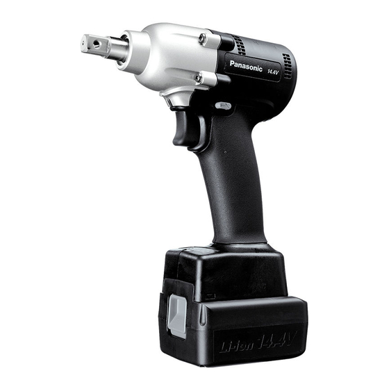
Cordless impact wrench
Hide thumbs
Also See for EYFMA1B:
- Operating instructions manual (216 pages) ,
- Operating instructions manual (60 pages)
Table of Contents
Advertisement
TABLE OF CONTENTS
1 Warning -------------------------------------------------------------- 2
2 Specifications ----------------------------------------------------- 2
3 Troubleshooting Guide ----------------------------------------- 3
4 Service Fixture and Adjustment----------------------------- 6
5 Disassembly and Assembly Instructions ---------------- 9
6 Measurements and Adjustments---------------------------15
7 Schematic Diagram ---------------------------------------------16
8 Wiring Connection Diagram ---------------------------------17
9 Exploded View and Replacement Parts List -----------18
Model No.
Model No.
Model No.
Europe
PAGE
© Panasonic Corporation 2015. All rights reserved.
Unauthorized copying and distribution is a violation
of law.
Order Number PTD1512E08CE
Cordless Impact Wrench
EYFMA1B
EYFMA1J
EYFMA1JR
PAGE
Advertisement
Table of Contents

Related Manuals for Panasonic EYFMA1B


Summary of Contents for Panasonic EYFMA1B
-
Page 1: Table Of Contents
5 Disassembly and Assembly Instructions ---------------- 9 6 Measurements and Adjustments---------------------------15 7 Schematic Diagram ---------------------------------------------16 8 Wiring Connection Diagram ---------------------------------17 9 Exploded View and Replacement Parts List -----------18 © Panasonic Corporation 2015. All rights reserved. Unauthorized copying and distribution is a violation of law. -
Page 2: Warning
1 Warning Caution: • Pb free solder has a higher melting point that standard solder; Typically the melting point is 50 - 70°F (30 - 40°C) higher. Please use a soldering iron with temperature control and adjust it to 750 ± 20°F (400 ± 10°C). In case of using high temperature solder- ing iron, please be careful not to heat too long. -
Page 3: Troubleshooting Guide
3 Troubleshooting Guide... -
Page 6: Service Fixture And Adjustment
4 Service Fixture and Adjustment 4.1. Check Parts Identify Procedure... -
Page 9: Disassembly And Assembly Instructions
5 Disassembly and Assembly Instructions 5.1. Disassembly Instructions Ref. No. 1A Procedure 1A Removal of Fixation cover. 1. Remove four screws where tightening fixation cover. 2. Pull off the fixing cover assembly. 3. Once removing the fixing cover, the driving shaft assembly may come out. - Page 10 Procedure 1A 1B 1C Ref. No. 1C Removal of Housing. 1. Remove nine housing screws. 2. Then open the housing A and B. NOTE: When opening the housings, make sure that the main PCB is on the housing A. If the main PCB sticks in the housing B and pull it out from the hous- ing A, the ribbon cable may be defected.
- Page 11 Procedure 1A 1B 1C 1D 1E Ref. No. 1E Removal of Motor assembly. 1. Separate the motor assembly from the driving shaft assembly. 2. Take out the motor rotor assembly from the motor stator. NOTE: Make sure not to damage the magnet by motor rotor. NOTE: Make sure not to scratch FET circuit by motor rotor.
- Page 12 5.2. Reassembly Instructions Ref. No. 2A Procedure 2A Assembly of Motor assembly. 1. Confirm if the metal powder is stuck around the rotor. If so, take out by something like packaging tape. 2. Insert the motor rotor into the stator. NOTE: Confirm the coil does not touch with the fan.
- Page 13 Procedure 2A 2B 2C Ref. No. 2C Assembly of Switch and Motor assembly. 1. Attach the quick connect terminal of the white lead wire from the motor stator with the switch assembly (M+). 2. Apply grease (FLOIL AH-137N-2 / WEWGW2) on the both side and both end of ribbon cable where insert into the connectors.
- Page 14 Procedure 2A 2B 2C 2D Ref. No. 2D Assembly of Driving assembly. 1. Confirm to attach the fixing rubber on Housing B. 2. Insert the motor and driving shaft assembly into the housing. 3. Confirm to set the motor lead wire (white) under the black lead wire and confirm if there is no pinching with switch.
-
Page 15: Measurements And Adjustments
6 Measurements and Adjustments 6.1. Trial Operation (after checking Troubleshooting Guide.) A. ASSEMBLY Confirm if there is NO gap between Housing A and B by pinching the lead wires. Confirm all screws are tightened firmly. Confirm if there is no deformation on the battery terminal. B. -
Page 16: Schematic Diagram
7 Schematic Diagram... -
Page 17: Wiring Connection Diagram
8 Wiring Connection Diagram... -
Page 18: Exploded View And Replacement Parts List
9 Exploded View and Replacement Parts List 9.1. Exploded View for EYFMA1B... - Page 19 9.2. Replacement Parts List for EYFMA1B Safety Ref. No. Part No. Part Name & Description Quantity Remarks WEYFMA1BK308 HOUSING AB SET WEYFMA1JL968 TIGHT SCREW W/WASHER (M4*25) WEYFMA1JS317 FIXATION COVER WEY6631K0867 SLIDER WEYFMA1BL119 ANVIL WEYFMA1JL107 DRIVING SHAFT ASSEMBLY WEY6504L1357 PLANET GEAR...
- Page 20 9.3. Exploded View for EYFMA1J...
- Page 21 9.4. Replacement Parts List for EYFMA1J Safety Ref. No. Part No. Part Name & Description Quantity Remarks WEYFMA1JK309 HOUSING AB SET WEYFMA1JL968 TIGHT SCREW W/WASHER (M4*25) WEYFMA1JS317 FIXATION COVER WEY6631K0867 SLIDER WEYFMA1JL117 ANVIL WEYFMA1JL107 DRIVING SHAFT ASSEMBLY WEY6504L1357 PLANET GEAR (2PCS/PK) WEY6506L1346 (2PCS/PK)
- Page 22 9.5. Exploded View for EYFMA1JR...
- Page 23 9.6. Replacement Parts List for EYFMA1JR Safety Ref. No. Part No. Part Name & Description Quantity Remarks WEYFMA1JK319 HOUSING AB SET WEYFMA1JL968 TIGHT SCREW W/WASHER (M4*25) WEYFMA1JS317 FIXATION COVER WEY6631K0867 SLIDER WEYFMA1JL117 ANVIL WEYFMA1JL107 DRIVING SHAFT ASSEMBLY WEY6504L1357 PLANET GEAR (2PCS/PK) WEY6506L1346 (2PCS/PK)