Table of Contents
Advertisement
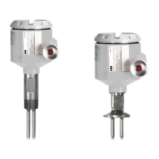
Operating instruction manual OI/TX-EN Rev. J
TX and TS
Thermal Dispersion Level Switches
Flow, level, granular solids and
temperature switch
K-TEK Products
Introduction
This operating instruction manual provides the following
information:
–
Calibration / set point procedure - see page 5
–
Configuration - see page 7
–
Installation instructions - see page 12
–
Troubleshooting - see page 18
Advertisement
Table of Contents

Related Manuals for ABB TX series


Summary of Contents for ABB TX series
- Page 1 Operating instruction manual OI/TX-EN Rev. J TX and TS Thermal Dispersion Level Switches Flow, level, granular solids and temperature switch K-TEK Products Introduction This operating instruction manual provides the following information: – Calibration / set point procedure - see page 5 –...
-
Page 2: Table Of Contents
9.2 Procedure for Measuring Voltage to the Sensor Using DVM (with power applied) ........18 9.2.1 With Power Disconnected Measure Resistance of Heater and Sensors ........18 10.0 APPENDIX A INSTRUMENT RANGEABILITY ....................19 10.1 TX Series ..............................19 10.1 IX Series ..............................19 11.0 APPENDIX B CONVERSION TABLE ......................20 12.0 APPENDIX C REMOTE MOUNTING ......................21 13.0 APPENDIX D TX HEATING VS. -
Page 3: Principle Of Operation
1.0 PRINCIPLE OF OPERATION ABB’s thermal dispersion switch consists of two temperature sensors (Resistance Temperature Detectors), heater, power supply, amplifier, current generator, comparator and a relay (DPDT) for output. The type of temperature sensor used is either a silicon semi-conductor, which is used on the standard units, or a platinum RTD which is used for high temperature applications (see ordering options on data sheets). -
Page 4: Explanations
2.0 EXPLANATIONS The TX Thermal Dispersion switch has two RTD elements, one of which is heated by a small, low wattage electric heating element. The thermal dispersion switch operates on the principle of a difference in thermal conductivity (TC) between mediums (air/vapor vs. liquid or high vs. low flows of air, vapor or liquid). Once the switch has stabilized in any given process condition, it can be adjusted such that a change (increase or decrease) in the amount of heat con- ducted away from the heated RTD (thermal dispersion) due to a change in thermal conductivity of the process at the sensors will cause the acative (heated) RTD to change in temperature (resistance). -
Page 5: Calibration / Set Point Procedure
B. Make connections to pins 1 and 3 of P2 (Pin 1 is nearest the green LED). 1. Temporarily insert small pieces of solid wire in P1 or P2; or, 2. Use ABB TX service plug connected to P1 on: a. Main board (using gender changer adapter) for (single relay output); or, b. -
Page 6: Calibrate From Low Tc (Thermal Conductivity) Process Conditions
Note that adjusting R18 affects both alarm recognition time (time for the TX switch to recognize an alarm condition at the sensors) as well as recovery time (time for the TX switch to recognize that the conditions have returned to normal) by positioning the “alarm/recovery”... -
Page 7: Configuration
*DEFAULT All TX series switches can be configured to function as a window comparator. That is, to detect between two different flow rates or two different temperatures. The switch can monitor for a combination of level and temperature, or flow and temperature with the dual switch point option. -
Page 8: Default Setting
4.0 CONFIGURATION (cont’d) Default Setting Switch set for Liquid Flow (Fail Safe Low Flow) JP 3: Relay setting as shown for State A Energizes when above flow set-point of R18 Two Jumpers x 2mm Switch set for Level or Air Flow (Fail Safe) High Level or High Flow JP3: Relay set for State B... - Page 9 4.0 CONFIGURATION (cont’d) LIQUID FLOW (BOTTOM BOARD) JP3 Jumper Configuration CONDITION State A State B Relay Energized LED On Flow > Set-Point Flow < Set-Point Fail Safe Normal Condition Normal Condition Relay De-energized LED OFF Flow < Set-Point Flow > Set-Point LEVEL OR AIR FLOW (BOTTOM BOARD) JP3 Jumper Configuration CONDITION...
-
Page 10: Second Switchpoint Option Board (Top Board)
Second Switchpoint Option Board (Top Board) The TX-2000 option board plugs into the TX-1000 main electronics module. It is mounted directly above the main module. It has two 3 pole terminal blocks that connect to the board’s double-pole double-throw relay contacts. These contacts can be set to switch at a set point that is independent of the setting on the main board. - Page 11 Second Switchpoint Option Board (Top Board) (cont’d) LIQUID FLOW (TOP BOARD) JP11 Jumper Configuration CONDITION State A State B Relay Energized LED On Flow < Set-Point Flow > Set-Point Relay De-energized LED OFF Flow > Set-Point Flow < Set-Point LEVEL OR AIR FLOW (TOP BOARD) JP11 Jumper Configuration CONDITION State A...
-
Page 12: Installation
5.0 INSTALLATION The instrument should be inserted into process line so that the wrench flats (the two flat sections between the pipe threads that permit you to torque the sensor head threads into the process line with a wrench) are perpendicular to the direction of flow. -
Page 13: Installation For Liquid Level Operation
Wiring Diagram - Dual Compartment Housing Wiring diagram for dual compartment housing (alumi- num and stainless steel). With the dual compartment housing option and /DS option there will only be one mV output 24-28 VDC SPDT switch (form C) available for each board. (You lose the DPDT function on each board.) Installation for Liquid Level Operation SIDE MOUNTED—The instrument can be mounted directly to the vessel being monitored or in a standpipe paral-... -
Page 14: Installation For Remote Electronics
Installation for Remote Electronics The remote electronics housing is used when the process environment is at a temperature that exceeds the maximum operating temperature (140°F or 65°C) of the electronics module. The remote housing simply contains a terminal block interface for a cable, which connects to another housing containing the electronics that is located in a more suitable environment. -
Page 15: Installation Setup
Installation Setup * For use on flanged valves only. High Flow Option TX - Standard Unit In flow applications the switch must see laminar flow. To assure laminar flow, allow a length of 10 times the diameter of the pipe size after a turn in a pipe before inserting the switch. If inserting the unit in a “tee” the tee size should be the same size as the line or smaller. -
Page 16: Flow Rate Detection
FLOW RATE DETECTION Configure circuit board jumpers JP3 (Relay State A) so the relay will be energized (green LED on) at the minimum flow rate then adjust as follows: Allow the product to flow at the minimum rate for approximately three minutes. (This will allow the unit to establish an accurate flow set point and delta voltage.) The orientation of the probe is important to minimize the time to respond to a minimum flow rate. -
Page 17: Temperature Switch Option
8.0 TEMPERATURE SWITCH OPTION In the temperature switch configuration, the heater can be disabled and the active RTD is not used. The reference RTD is used to measure the temperature of the process medium. The resistance of the reference RTD is directly propor- tional to temperature. -
Page 18: Troubleshooting
If the voltage measurements are incorrect then suspect board failure. It resistance measurements are incorrect suspect probe failure. Please call ABB Service Department for a replacement board or probe. If the voltage and resistance mea- surements are correct suspect incorrect setup or not allowing enough time for unit to switch. The switch has an inherent time delay. -
Page 19: Appendix A Instrument Rangeability
10.0 APPENDIX A Instrument Rangeability 10.1 TX Series 10.2 IX Series Operating instruction manual | TX Thermal Disperson Level Switches 19... -
Page 20: Appendix B Conversion Table
11.0 APPENDIX B - Conversion Table Examples: Example 1: 100 CFM in 4” line = 100 x .1884 = 18.84 F.P.S. Example 2: 10 G.P.M. in 3” line = 10 x .0434 = .434 F.P.S. Test Conditions: 60°F, 14.7PSIA, SCH. 40 Line 20 TX Thermal Disperson Level Switches | Operating instruction manual... -
Page 21: Appendix C Remote Mounting
12.0 APPENDIX C - Remote Mounting TERMINAL NUMBER Standard Temperature Range Special Temperature Range, Option H1 –320°F - +500°F SEE WIRE MARKERS TERMINAL NUMBER Special Temperature Range, Option H2 –100°F - +900°F Integral Electronics Remote Electronics Type J BLUE WHITE + DRAIN Cable (PVC) GREEN BLACK OF PAIR... -
Page 22: Appendix D Tx Heating Vs. Dispersion
13.0 APPENDIX D - TX Heating vs. Dispersion Above is a graph of the model TX probe. The longer line depicts the time response of the RTD by internal heating. The shorter line depicts the delta voltage or delta temperature or delta resistance decreasing when immersed in water. 22 TX Thermal Disperson Level Switches | Operating instruction manual... -
Page 23: Warranty Statement
ABB will repair or replace, at ABB’s election, defective items which are returned to ABB by the original purchaser within the period specified above from the shipment date of the item and which is found, upon examination by ABB, to its satisfaction, to contain de- fects in materials or workmanship which arose only under normal use and service and which were not the result of either alterations, misuse, abuse, improper or inadequate adjustments, applications or servicing of the product. -
Page 24: Customer Support
15.0 CUSTOMER SUPPORT ABB (USA, Canada, International) 18321 Swamp Road Prairieville, LA 70769 USA Tel: (1) 225.673.6100 Fax: (1) 225.673.2525 Email: service@ktekcorp.com Website: www.abb.com/level 24 TX Thermal Disperson Level Switches | Operating instruction manual... -
Page 25: Abb Rma Form
Be sure to include the Return Authorization (RA) number on the shipping label or package to the attention: Customer Service. A copy of this document should also be included with the packing list. ABB wants to maintain a safe work environment for its employees. - Page 26 26 TX Thermal Disperson Level Switches | Operating instruction manual...
- Page 27 Operating instruction manual | TX Thermal Disperson Level Switches 27...
- Page 28 Prairieville, LA 70769 USA notice. With regard to purchase orders, the agreed Phone: +1 225 673 6100 particulars shall prevail. ABB does not accept any Service: +1 225 677 5836 responsibility whatsoever for potential errors or possible lack of information in this document.