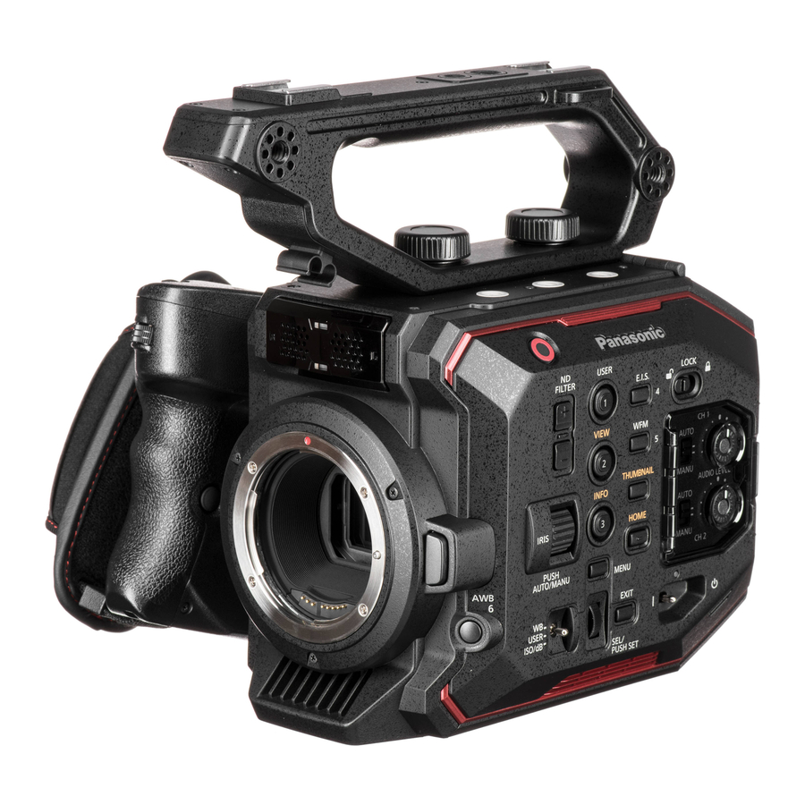
Panasonic AU-EVA1 Manual
Hide thumbs
Also See for AU-EVA1:
- Setup manual (8 pages) ,
- Manual (21 pages) ,
- Operating instructions manual (184 pages)
Table of Contents
Advertisement
Quick Links
Download this manual
See also:
Setup Manual
Advertisement
Table of Contents

Related Manuals for Panasonic AU-EVA1


Summary of Contents for Panasonic AU-EVA1
- Page 1 Book This document describes features available since Firmware Version 2.50 V2.51E...
-
Page 2: Table Of Contents
Table of contents 1. Sensor & format ........................5 1-1. Super 35mm sized imager with 5.7K resolution ............6 1-2. Active area ........................6 1-3. Record time ........................7 1-4. Applicable memory cards....................8 2. Preparation before filming ....................9 2-1. - Page 3 3-1-32. CARDS/MEDIA ...................... 42 3-1-33. CLIP NAME ......................42 3-1-34. 2 SLOTS FUNC..................... 42 3-1-35. PRE REC ....................... 42 3-1-36. REC FUNCTION ....................42 3-1-37. TC .......................... 43 3-1-38. AUDIO CH SETTINGS ................... 44 3-1-39. AUDIO INPUT ......................44 3-1-40.
- Page 4 5. File format ..........................73 5-1. Folder structure in the record media ................74 5-2. Folder name (MOV format) .................... 75 5-3. File name (MOV format) ....................76 6. Appendix ..........................77 6-1. Battery runtime ......................78 6-2. Scene file preset ......................79 6-3.
-
Page 5: Sensor & Format
1. Sensor & format... -
Page 6: Super 35Mm Sized Imager With 5.7K Resolution
1. Sensor & format The AU-EVA1 is a cinema camera recorder, featuring a newly developed super 35mm sized imager with 5.7K resolution, and can record in several formats and compression, offering up to 10-bit 4:2:2 even in 4K. The EVA1 contains V-Log/V-Gamut capture to deliver high dynamic range and a broad color gamut. -
Page 7: Record Time
1. Sensor & format 1-3. Record time (Bold: Available since firmware ver.2.02) Rec time Resolution Main Codec Frame rate Sampling (128GB) 29.97p, 24p, 25p, 422All-Intra 400M 4:2:2 10bit 23.98p 29.97p, 24p, 25p, 422LongGOP150M 4:2:2 10bit 1h50m 4096x2160 23.98p (4K) 420LongGOP150M 59.94p, 50p 4:2:0 8bit 1h50m... -
Page 8: Applicable Memory Cards
1. Sensor & format 1-4. Applicable memory cards Applicable type or speed class of SD memory card varies depends on record format and mode. Minimum requirement of speed class Record bit-rate, Format memory Speed Video record mode card type class speed class speed class 400Mbps... -
Page 9: Preparation Before Filming
2. Preparation before filming... -
Page 10: Terminals
2. Preparation before filming 2-1. Terminals Image resolution of HDMI and SDI OUT signals vary depend on the system settings. See 6-3. Output signals (SDI&HDMI) REAR VIEW USB2.0 HOST (for Wi-Fi SERVICE terminal adaptor connection) (for maintenance) PHONES OUT (3.5mm stereo) HDMI2.0 OUT (Support up to 4K60p 4:2:2 10-bit) -
Page 11: Accessory And Tripod Mounting Holes
2. Preparation before filming 2-2. Accessory and tripod mounting holes The AU-EVA1 has multiple standard screw holes for accessories, industrial standard 1/4-20UNC 3/8-16UNC size and cinema/broadcast equipment standard . Two holes are prepared on the carrying handle and eight holes on the top. -
Page 12: Home Screen
2. Preparation before filming 2-3. HOME screen Centralized control screen can be recalled by pressing the HOME button. Various functions can be rapidly accessed from this screen. HOME button COLOR (Gamma & Gamut) See P.13 for details. Switching ON/OFF VFR, and frame rate, Switching ON/OFF shutter, and rates to be listed can be added/removed angle/speed, display mode (deg./sec.) -
Page 13: Color Settings
2. Preparation before filming 2-3-1. COLOR settings On the AU-EVA1, settings of Gamma & Gamut is called “COLOR”. Image COLOR to be recorded can be set in the MAIN COLOR screen. COLOR settings for SDI, HDMI, and LCD output can individually be set. -
Page 14: Ei Setting
2. Preparation before filming 2-3-2. EI setting Setting of Exposure Index (ISO) Select adjustment criteria of ISO from Set ISO value which adjustable range 800BASE, 2500BASE, and NATIVE ONLY varies by ISO SELECT setting. *It is available since firmware version 2.02... -
Page 15: Audio Setting
2. Preparation before filming 2-3-3. AUDIO setting Assignment of audio channel sand setting of audio source. INT(R): Built-in MIC (R) INT(L): Built-in MIC (L) INPUT1: AUDIO INPUT1 INPUT1: AUDIO INPUT1 INPUT2: AUDIO INPUT2 LINE: AUDIO equipment is connected LINE: AUDIO equipment is connected MIC: MICROPHONE is connected MIC: MICROPHONE is connected... - Page 16 2. Preparation before filming 2-3-3. Audio setting (continued) The AU-EVA1 is equipped with a built-in stereo microphone and two external audio inputs. Different levels (LINE/MIC) can be assigned for external inputs. Setting audio (record with the built-in microphone) 1. In HOME screen, tap “AUDIO” item.
- Page 17 2. Preparation before filming 2-3-3. Audio setting (continued) Setting audio (record with the external microphone) 1. Switch OFF the power of the EVA1 and connect microphone(s) to AUDIO INPUT terminals. AUDIO INPUT1 AUDIO INPUT2 2. Switch ON the power of the EVA1 and tap “AUDIO” item at the HOME screen, and then set CH1 IN to INPUT1 and CH2 IN to INPUT2 for audio source.
- Page 18 MIC level can be set to -40dB, -50dB or -60dB as determined by MENU > AUDIO INPUT> INPUT MIC LEVEL. Choose the closest value with sensitivity your microphone has. Following is an example of one of Panasonic’s microphone AG-MC200G. With this microphone, choosing “-40dB” would be suitable as the closest value with the microphone.
-
Page 19: Info Screen
2. Preparation before filming 2-3-4. INFO screen This screen can be displayed by pressing INFO button in HOME screen mode. DIAGNOSTIC: See 6-4. Error and warning system (P.84) for details of error and warning messages. SWITCHES: Displays functions assigned to USER buttons at a glance. - Page 20 2. Preparation before filming 2-3-4. INFO screen (continued) VERSION: Displays firmware version of the unit. NETWORK: Displays network related settings.
- Page 21 2. Preparation before filming 2-3-4. INFO screen (continued) AUDIO: Displays audio related settings. MEDIA: Displays memory card status.
-
Page 22: User Assignable Buttons
2. Preparation before filming 2-4. User assignable buttons Features can quickly be recalled from 9 user assignable buttons and a dial. USER 8 (EXPAND) USER 9 (OPEN IRIS FA) USER 4 (EIS) USER 5 (WFM) USER 7 (SLOT SEL) USER 1 (ONE PUSH AF) USER 2 (PEAK/SQUARES FA) -
Page 23: Assigning Features
2. Preparation before filming 2-4-1. Assigning features MENU > SYSTEM SETTINGS > USER SWITCHES > Assign any function to any button. * See P.24 for assignable functions including their details. -
Page 24: Assignable Functions
2. Preparation before filming 2-4-2. Assignable functions ( ) : Feature that turns OFF when switch off the unit once. Menu item Description INHIBIT The USER button is disabled (nothing is assigned). Perform the auto white balance adjustment. Focus mode becomes AUTO while keep pressing the USER button. This ONE PUSH AF function works with lenses equipped with AF function. -
Page 25: Checking Functions Assigned To User Buttons
2. Preparation before filming 2-4-3. Checking functions assigned to USER buttons Press “HOME” button > “INFO” button > tap “SWITCHES” HOME screen Press “INFO” button 割り付けた機能一覧(SWITCHES 画面) HOME button INFO button... -
Page 26: Menu Settings
3. MENU settings... -
Page 27: Menu Items Over View
3. MENU settings 3-1. MENU items over view The AU-EVA1 has two levels of menu layers. MENU Purpose How to open Press “MENU” button or keep pressing LCD MENU Most basic advanced settings can be touch screen for 1 second while VIEW screen set in this layer. -
Page 28: System Mode
3. MENU settings (SYSTEM SETTINGS) 3-1-1. SYSTEM MODE Menu item Description Value (factory default setting underlined) FREQUENCY Set the system frequency 23.98p, 24.00p, 25.00p, 29.97p, 50.00p, 59.94p, 50.00i, 59.94i SDI RAW Set resolution for RAW data out. OFF, S35 5.7K, CROP 4K, CROP&MIX 2K 4-9. -
Page 29: User Switches
MONITOR VOL 3-1-4. SIDE LOCK Menu item Description Value (factory default setting underlined) The AU-EVA1 has a key lock switch, Keys LOCK , UNLOCK and a Dial to be locked or not can be USER 1 LOCK , UNLOCK selected. -
Page 30: Led & Fan
3. MENU settings (SYSTEM SETTINGS) 3-1-5. LED & FAN Value (factory default setting Menu item Description underlined) Set the tally lamp to be used TALLY LED FRONT, REAR, BOTH, OFF during recording. Set the access lamp to be used ACCESS LED ON, OFF when accessing memory card. -
Page 31: Language
3. MENU settings (SYSTEM SETTINGS) 3-1-9. LANGUAGE Menu item Description Value (factory default setting underlined) LANGUAGE Set the menu language * This menu item will not be displayed for some models and when the AREA SETTING item in the OPTION MENU (see P.57) is set to “AREA1”. 3-1-10. -
Page 32: Fps
3. MENU settings (CAMERA SETTINGS) 3-1-11. FPS Menu item Description Value (factory default setting underlined) VFR SW Turn ON/OFF variable ON , OFF frame rate mode. VALUE Set frame rate. The maximum number of frame rate (FPS) can vary depends on setting “SYSTEM SETTING > SENSOR MODE”. - Page 33 3. MENU settings (CAMERA SETTINGS) 3-1-13. EI Menu item Description Value (factory default setting underlined) MODE Set unit of Exposure Index ISO , dB (EI) ISO SELECT Set the EI control mode when ISO is selected in the NATIVE ONLY, 800BASE, 2500BASE MODE item.
-
Page 34: White
3. MENU settings (CAMERA SETTINGS) 3-1-14. WHITE Menu item Description Value (factory default setting underlined) Available when VALUE item is set to “AWB Perform Auto white balance adjustment MEMORY” only. VALUE Recall auto white balance ATW, AWB MEMORY, 3200K+0.0GMg, value on a preset table. 4300K+0.0GMg, 5600K+0.0GMg, 6300K+0.0GMg Add an AWB value to the... -
Page 35: Auto Black Balance
3. MENU settings (CAMERA SETTINGS) 3-1-18. E.I.S. Menu item Description Value (factory default setting underlined) Turn ON/OFF electric image ON, OFF stabilizer. ZOOM Set focal length of the lens for AUTO, MANUAL POSITION precise electric image stabilizing DATA operation. For AUTO adjustment, EF lenses that support providing focal length information is required. -
Page 36: Name Edit
3. MENU settings (SCENE FILE SETTINGS) 3-1-20. NAME EDIT Menu item Description Value (factory default setting underlined) NAME EDIT Edit scene file name Max. eight characters 3-1-21. SCENE DATA Menu item Description Value (factory default setting underlined) LOAD Load custom scene files from YES, NO the built-in memory. -
Page 37: Gamma
3. MENU settings (SCENE FILE SETTINGS) 3-1-23. GAMMA Menu item Description Value (factory default setting underlined) GAMMA Set gamma mode V-255570L1, V-504580L1, VIDEO, HLG SELECT Output (%) V-Log V-255570L1 V-504580L1 6 Input (stop) V-255570L1: Attaching importance to contrast The curve has 14 stop of latitude. The V-255570 means that start curve angle up to 10% is approx. -
Page 38: Knee
3. MENU settings (SCENE FILE SETTINGS) GAMMA (continued) Menu item Description Value (factory default setting underlined) MASTER GAMMA Set master gamma curve 0.30 -- 0.75 in units of 0.01. BLACK GAMMA Set depression and expansion of gamma (Depressing) -8 -- OFF -- +8 (Expanding) curve for dark areas. -
Page 39: Hlg Knee
3. MENU settings (SCENE FILE SETTINGS) 3-1-25. HLG KNEE Menu item Description Value (factory default setting underlined) Turn ON/OFF the Knee in HLG KNEE SW ON, OFF gamma mode. Set the Knee point in HLG KNEE POINT 55% -- 109% gamma mode in the units of 1%. -
Page 40: Chroma
3. MENU settings (SCENE FILE SETTINGS) 3-1-29. CHROMA Menu item Description Value (factory default setting underlined) Set chroma level of Pb and Pr LEVEL OFF, -99% -- 0% -- 99% signals. 3-1-30. MATRIX Menu item Description Value (factory default setting underlined) Turn ON/OFF the color matrix ON, OFF adjustment. -
Page 41: Color Correction
3. MENU settings (SCENE FILE SETTINGS) 3-1-31. COLOR CORRECTION Menu item Description Value (factory default setting underlined) Turn ON/OFF the color correction. ON, OFF Set saturation and phase of color on PARAM -63 -- 0 -- 63 16 color axes of a picture. Effect of color correction... -
Page 42: Cards/Media
3. MENU settings (REC SETTINGS) 3-1-32. CARDS/MEDIA Menu item Description Value (factory default setting underlined) FORMAT MEDIA Perform SD card format. SLOT1 , SLOT2 3-1-33. CLIP NAME Menu item Description Value (factory default setting underlined) CAM INDEX Set the camera ID code, to be recorded as the initial letter of A -- Z the clip name in MOV format. - Page 43 3. MENU settings (REC SETTINGS) 3-1-37. TC Menu item Description Value (factory default setting underlined) SET TC Set the timecode value. SET UB Set the users bit information. 00 -- FF TC/UB/Dur. timecode display TC = Timecode mode. UB = Users bit Dur.
-
Page 44: Audio Ch Settings
3. MENU settings (AUDIO SETTINGS) 3-1-38. AUDIO CH SETTINGS Value (factory default setting Menu item Description underlined) INT(L): Built-in microphone (L) Set audio source on the channel 1. INPUT1: AUDIO INPUT1 IN SELECT INT(R): Built-in microphone(R) Set audio source on the channel 2. INPUT1: AUDIO INPUT1 IN SELECT INPUT2: AUDIO INPUT2... -
Page 45: Audio Output
3. MENU settings (AUDIO SETTINGS) 3-1-40. AUDIO OUTPUT Menu item Description Value (factory default setting underlined) Set monitor audio output MONITOR OUT CH1, CH2, STEREO, MIX channel of phones out. Select audio output mode on phones out. Choose “LIVE” MONITOR DELAY when delay audible... -
Page 46: Sdi Out
3. MENU settings (OUTPUT SETTINGS) 3-1-43. SDI OUT Image resolution of SDI OUT signal varies depends on the combination of settings, see 6-3. Output signals (SDI&HDMI) (P.80) for the details. Menu item Description Value (factory default setting underlined) OUTPUT SW Turn ON/OFF SDI signal ON, OFF output. -
Page 47: Hdmi Out
3. MENU settings (OUTPUT SETTINGS) 3-1-44. HDMI OUT Image resolution of HDMI OUT signal varies depends on the combination of settings, see 6-3. Output signals (SDI&HDMI) (P.80) for the details. Menu item Description Value (factory default setting underlined) SIGNAL SEL Set output signal format on the SDI: Vary by OUT FORMAT setting HDMI OUT. -
Page 48: Sdi/Hdmi Indicator
3. MENU settings (OUTPUT SETTINGS) 3-1-45. SDI/HDMI INDICATOR Camera status information to be shown on the image can be set individually by SDI/HDMI OUTs. Menu item Description CLIP NAME Clip name PIXEL/FREQ System resolution and frequency for the main recorder MAIN COLOR COLOR (Gamma &... -
Page 49: Lcd Indicator
3. MENU settings (OUTPUT SETTINGS) 3-1-47. LCD INDICATOR Camera status information to be shown on the LCD image can be set individually. Menu item Description CLIP NAME Clip name PIXEL/FREQ System resolution and frequency for the main recorder MAIN COLOR COLOR (Gamma &... - Page 50 3. MENU settings (OUTPUT SETTINGS) LCD INDICATOR (continued) Camera status information to be shown on the LCD image can be set individually. Menu item Description Frame rate in FPS SHUTTER Shutter speed / open angle Exposure index WHITE Status of white balance adjustment 19,20 IRIS/ZOOM Zoom position and aperture level of the lens...
-
Page 51: Lcd Marker
3. MENU settings (OUTPUT SETTINGS) 3-1-48. LCD MARKER Marker characters to be shown on the LCD image can be set individually. Menu item Description Value (factory default setting underlined) CENTER Set shape of MARKER center marker SAFETY MARKER Set the type of safety 1:Boxed, 2:Corner only, OFF zone marker. -
Page 52: Lcd Ei Assist
3. MENU settings (OUTPUT SETTINGS) 3-1-50. LCD EI ASSIST Settings of Exposure index control related. Menu item Description Value (factory default setting underlined) ZEBRA Turn ON/OFF the zebra ON, OFF indicator on the LCD image. ZEBRA1 DETECT Set the zebra pattern1. 0% -- 80% -- 109% (Right downward) ZEBRA2 DETECT... -
Page 53: Lcd Levelgauge
3. MENU settings (OUTPUT SETTINGS) 3-1-51. LCD LEVELGAUGE Settings of level gauge to be displayed on the LCD image. Menu item Description Value (factory default setting underlined) LEVEL GAUGE Turn ON/OFF level gauge ON, OFF function. LEVEL GAUGE Set the current horizontal and RESET vertical position... -
Page 54: Scene File
3. MENU settings (FILE) 3-1-53. SCENE FILE Value (factory default setting Menu item Description underlined) Import custom scene files from the SD LOAD memory card. Store custom scene files to the SD SAVE memory card (overwrite to existing files). Store custom scene files to the SD SAVE AS memory card as a new file. -
Page 55: Network Sel
INFRA(MANUAL) Connect to a wireless access point. Access point can be searched by entering an SSID manually. Display network name of the SSID AU-EVA1 unit. Set connection type. (available BAND when TYPE item is set to 2.4GHz, 5GHz “DIRECT”) CHANNEL Set Wi-Fi channel of 2.4GHz... -
Page 56: Connection History
CLIENT: Request the IP address to external network device. Available in INFRA(SELECT) INFRA(MANUAL) modes. SERVER: Offer an IP address to a device connected to the AU-EVA1. IP ADDRESS Set an IP address. Available when DHCP setting is set to “OFF” or 192.168.0.1 “SERVER”. -
Page 57: Area Settings
3. MENU settings (OPTION メニュー) *** This menu item is not available for AU-EVA1MC and AU-EVA1EJ models. *** 3-1-60. AREA SETTINGS Menu item Description Value (factory default setting underlined) Change certain menu items such as AREA DATE FORMAT, HEADROOM by AREA1, AREA2, AREA3 SETTINGS area setting. -
Page 58: Understanding Advanced Features
4. Understanding advanced features... -
Page 59: Understanding Variable Frame Rate (Vfr) Recording
4. Understanding advanced features 4-1. Understanding Variable Frame Rate (VFR) recording How to use 1. Set following 3 items to use the VFR function in MENU > SYSTEM SETTINGS > SYSTEM MODE. The maximum available frame rates (up to 60, 120, or 240fps) varies with the “SENSOR MODE”... -
Page 60: Monitoring Image And Recording
4. Understanding advanced features 4-2. Monitoring image and recording The AU-EVA1 has an HDMI 2.0 terminal and a 6G-SDI OUT, images can be output from these terminals at the same time in different resolutions. The same content display with LCD MONITOR available on the SDI OUT as the LCD crone display function. -
Page 61: Understanding Focus Assist Modes
4. Understanding advanced features 4-3. Understanding focus assist modes The AU-EVA1 has five different focus assist modes, they can be individually recalled with USER assignable buttons (except for monochrome focus assist mode). EXPAND Part of image can be magnified up to 4 times... - Page 62 4. Understanding advanced features 4-3. Understanding focus assist feature (continued) FOCUS SQUARE Green square boxes are displayed on the viewfinder image, whose size increases as the object behind the box comes into focus. Adjust focus ring/control so that size of the boxes over the subject/area of interest become maximum.
-
Page 63: Understanding Sport Meter As Exposure Index (Ei) Assist
SPOT METER function. Overwiew The graph on the figure 4-1 shows the AU-EVA1’s V-Log gamma curve. It is designed to have the same characteristic as the original VARICAM’s (35 and LT) curve hense, LUTs developed for VARICAM series can also be used for the AU-EVA1’s footage, Please note that EVA1 exposure latitude is 14 stop while VARICAM35/LT is 14.5 stops.. - Page 64 4. Understanding advanced features 4-4. Using sport meter as Exposure Index (EI) assist Adjusting EI with percent (%) display (example) 1. Set display unit of the spot meter function. MENU > OUTPUT SETTINGS > LCD EI ASSIST > SPOT METER UNIT > % 2.
-
Page 65: Understanding Electric Image Stabilizer (Eis) Function
4. Understanding advanced features 4-5. Understanding Electric Image Stabilizer (EIS) function The AU-EVA1 is equipped with an image stabilization function that works electrically with assistance of built-in gyro sensors. The following figure illustrates the effective area of the function, and the area for motion detection and stabilizing (which is wider than the normal Super35 image area). -
Page 66: Understanding Dual Memory Card Slot Feature
4. Understanding advanced features 4-6. Understanding dual memory card slot feature SIMUL (Simultaneous) Record the same content onto two SD memory cards simultaneously. Even if recording stops on one card unexpectedly, recording on the other card can continue. Record Record ・... -
Page 67: Synchronize Timecode
4. Understanding advanced features 4-7. Synchronize timecode The AU-EVA1 has a timecode IN/OUT terminal (common use for IN and OUT). The following describes workflow know-how when using timecode synchronization feature with two AU-EVA1. Synchronize TCG 01:20:00:20 TCG 01:20:00:20 Preparation 1. Connect TC IN/OUT terminals on both master and slave units with a BNC cable. -
Page 68: Understanding Remote Operation Via Eva Rop Application
EVA ROP application Panasonic AJ-WM50 etc. Setting up equipment (Overview) 1. Install the Panasonic EVA ROP application from Apple App Store or Google Play to the tablet device. 2. Connect the wireless module to the USB2.0 HOST terminal on the AU-EVA1. - Page 69 Enter SSID name (Default: AU-EVA1) SSID Choose “2.4GHz” or “5GHz” depends on Wi-Fi adaptor type. BAND CHANNEL(2.4GHz) AUTO CHANNEL(5GHz) AUTO Enter connection password used to connect to the AU-EVA1 from ENCRYPT KEY the tablet device. (Default: 01234567890123456789abcdef) DHCP SERVER IP ADDRESS Default:192.168.0.1 SUBNET MASK Default:255.255.255.0...
- Page 70 1. Install the Panasonic EVA ROP app from App Store. 2. Open “Setting” > Wi-Fi > “, and choose an SSID of the AU-EVA1 (example AU-EVA1). 3. Enter connection password (factory default: 01234567890123456789abcdef) to connect to the AU-EVA1 via Wi-Fi network.
-
Page 71: Understanding Raw Output Feature
4. Understanding advanced features 4-9. Understanding RAW output feature 10-bit RAW data output is available for the greatest flexibility in post image adjustment. The RAW data is output from SDI OUT (RAW data cannot be recorded with the built-in recorder in the EVA1). 6G SDI x1 Settings to use RAW data output 1. -
Page 72: Updating Firmware
4. Understanding advanced features 4-10. Updating firmware 1. Download firmware package from the support website at https://panasonic.biz/cns/sav/pass_e 2. Unzip the package and copy “UPDATE.HDC” file to the ROOT (the top-most) directory in the SD memory card. Copy to Root Extract directory 3. -
Page 73: File Format
5. File format... -
Page 74: Folder Structure In The Record Media
5. File format 5-1. Folder structure in the record media Folder structure example SD card volume PRIVATE PANA_GRP 001QAQAM Video data (4K 59.94p, LPCM audio) 002RCQAM Video data (UHD 29.97p, LPCM audio) clips BACKUP.TMP For file management INDEX.DAT For file management AVCHD AVCHDTN Thumbnail data... -
Page 75: Folder Name (Mov Format)
5. File format 5-2. Folder name (MOV format) Folders storing MOV clips are named depends on resolution, frame rate, video format, and other settings below. Example B002 PRIVATE PANA_GRP 0 01QA QAM 001QAQAM 002RCQAM Record mode Fixed Scan mode Frame rate Resolution File number (incremental) Example: a folder is named as “001QAQAM”... -
Page 76: File Name (Mov Format)
5. File format 5-3. File name (MOV format) The AU-EVA1 supports 20-digits cine style clip naming for MOV clips as the same structure with VARICAM series (AU-V35LT1G etc.) for easy clip management. Example of cine style file name B 0 0 2 C 0 1 0 - 1 7 0 9 1 8 - E 1 2 5 . m o v... -
Page 77: Appendix
6. Appendix... -
Page 78: Battery Runtime
6. Appendix 6-1. Battery runtime Voltage & capacity Part number Hours to charge Operation time (Minimum) 7.28V 3h 20min 2h 50min 5900mAh, 43Wh VW-VBR59 (comes standard/optional) 7.28V 4h 00min 4h 15min 8850mAh, 64Wh VW-VBR89G (Optional) 7.28V 4h 40min 5h 40min 11800mAh, 86Wh VW-VBR118G (Optional) -
Page 79: Scene File Preset
6. Appendix 6-2. Scene file preset MAIN Menu item SCENE1 SCENE2 SCENE3 SCENE4 SCENE5 (eV-LOOK1) (eV-LOOK2) (BC-LOOK1) (BC-LOOK2) (HDR) M.PED R PED G PED B PED PEDESTAL OFFSET GAMMA SELECT V255570L1 V504580L1 VIDEO VIDEO MASTER GAMMA 0.45 0.50 BLACK GAMMA B.GAMMA RANGE KNEE SW... -
Page 80: Output Signals (Sdi&Hdmi)
6. Appendix SDI OUT 6-3. Output signals (SDI&HDMI) Image resolution of SDI OUT signal varies depends on the combination of settings below. MENU > SYSTEM SETTINGS > SYSTEM MODE > FREQUENCY and MAIN PIXEL MENU > OUTPUT SETTINGS > SDI OUT > SIGNAL SEL and OUT FORMAT MENU SETTING SIGNAL OUT FORMAT (OUT FORMAT MENU ITEM) - Page 81 6. Appendix SDI OUT 6-3. Output signals (SDI&HDMI) Image resolution of SDI OUT signal varies depends on the combination of settings below. MENU > SYSTEM SETTINGS > SYSTEM MODE > FREQUENCY and MAIN PIXEL MENU > OUTPUT SETTINGS > SDI OUT > SIGNAL SEL and OUT FORMAT MENU SETTING SIGNAL OUT FORMAT (OUT FORMAT MENU ITEM)
- Page 82 6. 付録 6. Appendix HDMI 出力 HDMI OUT 6-3. Output signals (SDI&HDMI) Image resolution of HDMI OUT signal varies depends on the combination of settings below. MENU > SYSTEM SETTINGS > SYSTEM MODE > FREQUENCY and MAIN PIXEL MENU > OUTPUT SETTINGS > HDMI OUT > SIGNAL SEL and OUT FORMAT MENU SETTINGS SIGNAL OUT FORMAT FREQU...
- Page 83 6. Appendix HDMI OUT 6-3. Output signals (SDI&HDMI) Image resolution of HDMI OUT signal varies depends on the combination of settings below. MENU > SYSTEM SETTINGS > SYSTEM MODE > FREQUENCY and MAIN PIXEL MENU > OUTPUT SETTINGS > HDMI OUT > SIGNAL SEL and OUT FORMAT MENU SETTINGS SIGNAL OUT FORMAT FREQU...
-
Page 84: Error And Warning System
6. Appendix 6-4. Error and warning system When the AU-EVA1 detects any error or system trouble, the camera alearts is indicated on the LCD monitor (HOME and VIEW screen), and the tally lamp. SYSTEM ERROR WARNING... - Page 85 6. Appendix 6-4. Error and warning system When the AU-EVA1 detects any error or system trouble, the camera alearts is indicated on the LCD monitor (HOME and VIEW screen), and the tally lamp. ALERT...
- Page 86 6. Appendix 6-4. Error and warning system MESSAGE...
- Page 87 6. Appendix 6-4. Error and warning system MESSAGE...
-
Page 88: Troubleshoot (Invalid Error Message)
6. Appendix 6-5. Troubleshoot (INVALID error message) Following tables show major causes and ways to cope with “INVALID” error message. When occurred? Cause Remedy White balance mode is NOT set to Set CAMERA SETTINGS > WHITE > VALUE > AWB Executed Auto white AWB. - Page 89 6. Appendix 6-5. Troubleshoot (INVALID error message) Following tables show major causes and ways to cope with “INVALID” error message. When occurred? Cause Remedy REC CHECK function does not work while in recording, stop INTERVAL record mode is running. recording and try again. REC CHECK function does not work while SIMUL mode is SIMUL record mode is being turned working.
- Page 90 6. Appendix 6-5. Troubleshoot (INVALID error message) Following tables show major causes and ways to cope with “INVALID” error message. When occurred? Cause Remedy SD card being mounted is just one. Need two cards to perform SLOT Mount one more SD card. SEL.
- Page 91 6. Appendix 6-5. Troubleshoot (INVALID error message) Following tables show major causes and ways to cope with “INVALID” error message. When occurred? Cause Remedy Tapped the LCD MAIN COLOR setting is NOT set to Set SYSTEM SETTINGS > COLOR SETTINGS > MAIN > screen to set SDI OUT V-Log.
-
Page 92: Genuine Accessories
6. Appendix 6-6. Genuine accessories Mic-holder adaptor (with 1x 6mm screw) Carrying handle Part No. 1KP1AUEVA1Z Part No. 1KH1AUEVA1Z Mic-holder mounting screes (12mm in length) Part No. VYC1144 (2pcs.) Mic-holder, Part No. VYC1146 Grip, Part No. 2YM2AUEVA1Z Grip belt, Part No. VFC5098 LCD monitor mounting bracket LCD monitor, Part No. - Page 93 6. Appendix AU-EVA1 Genuine accessory Battery packs (Quick charging with AG-BRD50 charger available with AG-VBR series packs) AG-VBR118G AG-VBR89G AG-VBR59 VW-VBD58 (11,800mAh) (8,850mAh) (5,900mAh) (5,800mAh) Battery charger Microphone AG-BRD50 AJ-MC200G (Supports quick charging with (+48V, XLR) AG-VBR battery packs) Wireless LAN module AJ-WM50 (Supports 2.4GHz / 5GHz)
-
Page 94: Specifications
6. Appendix 6-7. Specifications General specification DC 7.28 V (Battery Operation) Power DC 12 V (AC adapter operation) Power Consumption 19 W (when using LCD monitor) Operating Temperature 0 °C to 40 °C (32°F to 104°F) Operating Humidity 10% to 80% (relative humidity) Storage Temperature -20 °C to 60 °C (-4°F to 140°F) Body: Approx. - Page 95 6. Appendix Memory card recorder SDHC memory card (4 GB to 32 GB) SDXC memory card (32 GB to 128 GB) Recording Media UHS-Ⅰ/UHS-Ⅱ UHS Speed Class3 is supported, Video Speed Class V90 is supported Recording Slot SD memory card slot x 2 4096 x 2160 (4K), 3840 x 2160 (UHD), Recording Resolution 2048 x 1080 (2K), 1920 x 1080 (FHD),...
- Page 96 6. Appendix Video output 0.8 V [p-p], 75 Ω, 4K (6G), HD (3G/1.5G) Output format (4:2:2 10 bit): ・ 4096 x 2160: 29.97p, 25p, 24p, 23.98p ・ 3840 x 2160: 29.97p, 25p, 24p, 23.98p ・ 1920 x 1080: 59.94p, 50p, 59.94i, 50i, 29.97p, 29.97PsF, 25p, 25PsF, 24p, 24PsF, 23.98p, 23.98PsF SDI OUT ・...
- Page 97 6. Appendix LCD monitor 3.5-type LCD monitor (approx. 1,150,000 dots) Size Touch panel (MENU control, Shooting assist functions) Switches MIRROR (OFF, B/T, ROTATE) Hand grip Mounting One touch rotatable/Detachable Mechanism Switches REC, MENU.MENU/IRIS multifunctional dial, User switch x 2 Accessories comes standard Battery (5900mAh), Battery charger, AC adapter, AC cable, Shoulder Accessories strap, Microphone holder, Microphone holder adapter, LCD monitor (with...
-
Page 98: Dimensions
6. Appendix 6. Appendix 6-8. Dimensions... -
Page 99: Revision History
Revision history Document Issued History Version Jan 2018 First edition issued V1.00E Added Apr 2018 V2.00E - Description of new features, available since the firmware ver2.02. Added - Description of the changes and enhancements with the firmware June 2018 V2.50E ver 2.50. - Page 100 Panasonic Corporation Download firmware, check frequently asked questions for the https://panasonic.biz/cns/sav/pass_e...