Table of Contents
Advertisement
Quick Links
GE
Digital Solutions
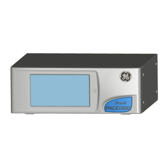
Pressure Automated Calibration Equipment
User manual - K0470 Revision A
PACE Indicators
© 2010 General Electric Company. All Rights Reserved. Specifications are subject to change
without notice. GE is a registered trademark of General Electric Company. Other company or
product names mentioned in this document may be trademarks or registered trademarks of their
respective companies, which are not affiliated with GE.
Advertisement
Table of Contents

Related Manuals for GE K0470


Summary of Contents for GE K0470
- Page 1 © 2010 General Electric Company. All Rights Reserved. Specifications are subject to change without notice. GE is a registered trademark of General Electric Company. Other company or product names mentioned in this document may be trademarks or registered trademarks of their...
- Page 2 Technical Advice For technical advice contact the manufacturer. * A qualified technician must have the necessary technical knowledge, documentation, special test equipment and tools to carry out the required work on this equipment. [EN] English K0470 Revision A...
- Page 3 General purpose interface bus Rt CAS Rate of Calibrated airspeed Mercury Rt MACH Rate of MACH Hertz Receive data Standard commands for Indicated airspeed SCPI programmable instruments IDOS Intelligent digital output sensor (GE product) Sales data sheet K0470 Revision A [EN] English...
- Page 4 Metre Negative milliampere °C Degrees Celsius Maximum °F Degrees Fahrenheit mbar Millibar Related publications K0467 User Guide and Safety Instructions K0469 PACE Heritage Communications Manual K0450 PACE Series Calibration Manual K0472 PACE Series SCPI Manual [EN] English K0470 Revision A...
- Page 5 BEFORE APPLYING PRESSURE, EXAMINE ALL FITTINGS AND EQUIPMENT FOR DAMAGE. REPLACE ALL DAMAGED FITTINGS AND EQUIPMENT. DO NOT USE ANY DAMAGED FITTINGS AND EQUIPMENT. DO NOT EXCEED THE MAXIMUM WORKING PRESSURE OF THE INSTRUMENT. THIS EQUIPMENT IS NOT RATED FOR OXYGEN USE. K0470 Revision A [EN] English...
- Page 6 O @ 60°F 0.097890364 29.8516987 Unit Conversion Convert FROM pressure VALUE 1 in pressure UNITS 1 TO pressure VALUE 2 in pressure UNITS 2, calculate as follows: VALUE 2 VALUE 1 x FACTOR 1 FACTOR 2 [EN] English K0470 Revision A...
-
Page 7: Table Of Contents
Preparation for Use Connecting the Instrument Mounting kits Electrical connections 2-10 OPERATION Preparation Power-up Sequence Measure Mode Operation and Example Procedures Global Set-up Selections 3-11 Supervisor Set-up 3-12 Instrument Status 3-13 MAINTENANCE Introduction Visual inspection Cleaning K0470 Revision A [EN] English... - Page 8 REFERENCE AND SPECIFICATION Installation notes Reference port Icons Measure Set-up Status Global Set-up Supervisor Set-up Calibration 6-27 Specification 6-27 6.10 Options 6-28 6.11 Installation and Ancillary Equipment 6-31 6.12 Return Goods/Material Procedure 6-31 6-13 Packaging Procedure 6-31 [EN] English K0470 Revision A...
- Page 9 Intentionally blank K0470 Revision A viii [EN] English...
-
Page 10: Description
The instrument can be used as follows: • Free-standing instrument positioned on a horizontal surface. • Rack-mounted in a standard 19 inch rack using the rack-mount option kit. • Panel mount using the panel-mount option kit. [EN] English 1 - 1 K0470 Revision A... - Page 11 1 Description Options available for the PACE1000 refer to the data sheet. Information and notes on applications (Ref: Reference and Specification, Section 6) or www.gemeasurement.com K0470 Revision A 1 - 2 [EN] English...
-
Page 12: Installation
Check the contents of the PACE1000 packaging with the list that follows: Packaging List - PACE1000 PACE1000 Pressure Indicator. Adaptor, power supply (GE part number 191-370). iii) User guide and safety instructions, and CD containing the full documentation suite. Calibration certificate. -
Page 13: Connecting The Instrument
Note: For instruments with NPT connections, use applicable bonded sealing as shown in figure below. ISO 228 G1/8 ISO 228 G1/8 bonded seal bonded seal Recommended method Alternative method below 100 bar Figure 2-1, Sealing Pneumatic Connections K0470 Revision A 2 - 2 [EN] English... - Page 14 Make sure the user systems can be isolated and vented. Connect the Unit Under Test (UUT) to the output connection port. Note: For instruments with NPT connections, use applicable bonded sealing as shown in figure below. [EN] English 2 - 3 K0470 Revision A...
- Page 15 Switch off the power supply before connecting or disconnecting the instrument. Use the appropriate sealing method for all pressure connections. Note: For instruments with NPT connections, use applicable bonded sealing as shown in figure below. K0470 Revision A 2 - 4 [EN] English...
- Page 16 ISO 228 Male to AN6 37° Male IO-ADAPT-BARB ISO 228 Male to 1/4 Hose IO-ADAPT-1/4NPT ISO 228 Male to 1/4 NPT Female Refer to the data sheet for the range of adaptors. [EN] English 2 - 5 K0470 Revision A...
- Page 17 Observe absolute cleanliness when using the instrument. Severe damage can be caused if equipment connected to this instrument is contaminated. Connect only clean equipment to the instrument. To avoid any contamination, an external filter is recommended. K0470 Revision A 2 - 6 [EN] English...
- Page 18 The hydraulic liquid must be clean, refer to specification given in the Data sheet. Connect the Unit Under Test (UUT) to the appropriate connection port. Fill and bleed the UUT and connecting pipes. [EN] English 2 - 7 K0470 Revision A...
-
Page 19: Mounting Kits
Refer to the electrical connections below before fitting the instrument into the equipment rack. Temporarily locate the two spigots* to each side of the equipment rack. Locate and slide the instrument into the rack. Locate the instrument on the spigots*. K0470 Revision A 2 - 8 [EN] English... - Page 20 Support the instrument and connect the cables and pipes. Refer to the electrical connections below before fitting the instrument into the panel. Secure the instrument in the panel with four screws and washers [EN] English 2 - 9 K0470 Revision A...
-
Page 21: Electrical Connections
REAR PANEL. CAUTIONS Use the power adaptor supplied with the instrument (GE part no. 191-370). Using other power adaptors may cause over-heating, this can result in a fire. Do not let the power adaptor come into contact with any moisture or liquids. - Page 22 The pin connections for the 9-pin D-type, RS232 connector and the relationship between the instrument and the RS232 control signals, together with device interconnection interface is shown in Table 2-1. The instrument is configured as Data Circuit Terminating Equipment (DCE). [EN] English 2 - 11 K0470 Revision A...
- Page 23 DCE Ready internally Equipment Connector Cable Screen chassis shell Table 2-1, RS232 Connections Handshaking connections Software handshaking use: TXD, RXD and GND. Hardware handshaking use: TXD, RXD, GND, CTS, RTS and DTR. K0470 Revision A 2 - 12 [EN] English...
- Page 24 Repeat this procedure for all the instruments in the system. Use the Supervisor set-up (communications) menu on each instrument to set-up the required communication parameters (Ref: Section 3.8). [EN] English 2 - 13 K0470 Revision A...
- Page 25 2 Installation Figure 2-8 - IEEE 488 Connection K0470 Revision A 2 - 14 [EN] English...
-
Page 26: Operation
The touch screen shows the measured pressure in the parameters selected in set-up. The instrument is now ready for use. Do not touch the display screen during power-up [EN] English 3 - 1 K0470 Revision A... -
Page 27: Measure Mode
1 Pressure reading 2 Functions enabled 3 Zero key (vent system before starting zero sequence) 4 Function area 5 Status area 6 Current pressure range Display Icons Tare enabled Filter pressure reading Percentage Ethernet not connected Reference level difference Ethernet connected (gas head correction) K0470 Revision A 3 - 2 [EN] English... - Page 28 Function area Min/Avg/Max is performed on the reading selected for display in the top screen. The Ethernet LAN Status indication (1) shows the following: • Colour red - not connected • Colour green - connected [EN] English 3 - 3 K0470 Revision A...
- Page 29 3 Operation Data Logging The “Datalog” icon (1) is present when a memory card is fitted: K0470 Revision A 3 - 4 [EN] English...
- Page 30 PACE Pressure Indicators User Manual [EN] English 3 - 5 K0470 Revision A...
- Page 31 3 Operation K0470 Revision A 3 - 6 [EN] English...
- Page 32 3.6: More next page: Status Exit set-up. Next page of menu options. Loops Absolute range selection available when from last page to first page. barometric option installed. Stores settings and exits set-up. [EN] English 3 - 7 K0470 Revision A...
-
Page 33: Operation And Example Procedures
When selected, e.g. Basic, the screen changes to show the selected task. To measure pressure in the task proceed as follows: Select the required units of pressure measurement from the measure set-up menu. K0470 Revision A 3 - 8 [EN] English... - Page 34 • QNH - Atmospheric pressure at Mean Sea Level (MSL) (may be local, measured pressure or a Regional Forecast Pressure (RFP). When set on altimeter it reads altitude. Runway (on Earth’s surface) QNE QNH QFE 29.9212 inHg (1013.25 kPa) Sea Level Reference Datum Datum (adjusted) [EN] English 3 - 9 K0470 Revision A...
- Page 35 On completion, the display shows the leak rate results with leak rate per second or per minute in the current pressure units selected in measure set-up. Leak test Start Settings Test time /second Leak rate /minute K0470 Revision A 3 - 10 [EN] English...
-
Page 36: 3.5 Global Set-Up Selections
Recall current user set-up Resolution - Measure display resolution Display Back light - % brightness - Timer (time-out) setting Audio volume - % of full volume Satus area Function area Reading Display Mode Graph [EN] English 3 - 11 K0470 Revision A... -
Page 37: Supervisor Set-Up
Enter the equivalent value in Pascals Instrument alias name Language Europe North America Area of Use Japan Asia Rest of World Restore last settings Restore previous defaults Y/N? Additional selections for options enabled: Aeronautical etc. K0470 Revision A 3 - 12 [EN] English... -
Page 38: Instrument Status
Analogue O/P Boot ROM Software VFC Main Code Hardware VFC Boot ROM Message Ethernet (optional) IEEE488* Communications RS232* Ethernet * current settings, see 6.7 Current set-up More next page: Support Contact details [EN] English 3 - 13 K0470 Revision A... - Page 39 Instrument Main Code Instrument OS Build Instrument Boot ROM Example Additional selections for options enabled: Analgue etc. Analogue O/P Main Code Analogue O/P Boot ROM Exit set-up. VFC Main Code VFC Boot ROM K0470 Revision A 3 - 14 [EN] English...
-
Page 40: Maintenance
Inspect for obvious signs of damage and dirt on the following: External of the instrument. Power supply adaptor Associated equipment. Damaged parts must be replaced contact GE Service. For cleaning (Ref: Cleaning Section 4.3). Cleaning CAUTION Do not use solvents for cleaning. - Page 41 4 Maintenance Intentionally blank K0470 Revision A 4 - 2 [EN] English...
-
Page 42: Testing And Fault Finding
4. Record the PACE auto IP address (The test screen below has auto IP address 3.115.21.237) 5. Open the PC command prompt screen. 6. Using the “ping” command, ping the PACE IP address (see screen capture below). The PACE will reply if operating correctly. [EN] English 5 - 1 K0470 Revision A... - Page 43 Ethernet open ports and their usage: 80/tcp PACE Web server (http) 111/tcp ONC RPC port mapper 372/tcp VXI-11 communication (Dynamically allocated) 443/tcp Web server (https) 5025/tcp PACE SCPI communication socket 111/udp ONC RPC port mapper K0470 Revision A 5 - 2 [EN] English...
- Page 44 PACE Pressure Indicators User Manual Ethernet testing using a web browser [EN] English 5 - 3 K0470 Revision A...
-
Page 45: Fault Finding
Vent system pressure. Instrument will not zero. Check for blockage. Contact approved service agent for repair. Table 5.1 - Fault Diagnosis Approved Service Agents For the list of service centres logon to www.gemeasurement.com K0470 Revision A 5 - 4 [EN] English... -
Page 46: Reference And Specification
1.228 1.219 1.210 1.201 1.193 1.259 1.249 1.240 1.231 1.222 1.213 1.204 1.271 1.261 1.252 1.243 1.234 1.225 1.216 1.283 1.274 1.264 1.255 1.246 1.237 1.228 Note: 100 kPa = 1 bar [EN] English 6 - 1 K0470 Revision A... -
Page 47: Reference Port
The indicator and UUT references should be connected together (using the optional differential connection kit) to provide a common reference to atmosphere. K0470 Revision A 6 - 2 [EN] English... -
Page 48: Icons
Correction source Correction SCM Correction sensor sensor Correction valve Current set-up Date & time Diagnostic Diagnostic Delete analogue output barometric option Diagnostic control Diagnostic sensor controller Diagnostic source Diagnostic general Diagnostic RS232 sensor [EN] English 6 - 3 K0470 Revision A... - Page 49 Information Instrument In limits Instrument accuracy Instrument alias Language Leak test name Lock Lock tasks Logic output Max-min Max peak Min peak Nudge Passive mode Percentage Power-up Preset Pressure Pressure filter Process K0470 Revision A 6 - 4 [EN] English...
- Page 50 Set serial number Set time Set-up zero Slew rate linear Slew rate max rate Software upgrade Software build Software upgrade history Status Status area Step (single) Stop Supervisor set-up Switch test Tare Support Task [EN] English 6 - 5 K0470 Revision A...
-
Page 51: Measure Set-Up
“captured” as the tare value. The display shows the selected tare value in the pressure window. Peak: Maximum, minimum and average display of pressure readings. Task Selecting Task enables a set of pre-determined functions and software enabled optional functions. K0470 Revision A 6 - 6 [EN] English... -
Page 52: Status
Communications, IEEE 488 and RS232 are fitted as standard. Additional communication types are options - USB and Ethernet. f. Current set-up - read only data. g. Support • List contact information for support and advice. [EN] English 6 - 7 K0470 Revision A... -
Page 53: Global Set-Up
Save/recall user set-up Save user set-up. Recall user set-up. Display Resolution Backlight Audio volume Status area Display Mode • Reading (default) • Graph * The instrument date and time must have been set correctly. K0470 Revision A 6 - 8 [EN] English... -
Page 54: Supervisor Set-Up
Data throughput. Baud rates slower than 115k2 baud will slow the new data update rate pro-rata. Even at a 115k2 baud rate the readings are slower than using IEEE. IDOS is a slower sensor than internal sensors. [EN] English 6 - 9 K0470 Revision A... - Page 55 PACE 1000 equipment. This procedure only allows supervisor to select these user pre-installed values. To initially define / change or delete the RS232 Comms Range values, refer to (Ref: K0472 PACE SCPI Remote Communications Manual). K0470 Revision A 6 - 10 [EN] English...
- Page 56 PACE Pressure Indicators User Manual On the main screen, touch any of the three horizontal touch areas on the screen. On the MEASURE SETUP screen, select GLOBAL SETUP. [EN] English 6 - 11 K0470 Revision A...
- Page 57 6 Reference and Specification Select SUPERVISOR SETUP. Enter the Supervisor PIN and press the top touch area. Use the back arrow in the top right corner of the screen to delete any incorrect data entries. K0470 Revision A 6 - 12 [EN] English...
- Page 58 On the SUPERVISOR screen, select COMMS. On the COMMUNICATIONS screen, select COMMS RANGE SETUP. On the COMMS RANGE SETUP, Use the Up and Down arrows to highlight the desired Range (Ranges 1 to 10). [EN] English 6 - 13 K0470 Revision A...
- Page 59 A firewall protects the Ethernet connection. The firewall is always turned on. The following ports are unfiltered to allow remote communication and control. Port Description 80/tcp http (Web server) 111/tcp rpcbind (RPC for VXI) 111/udp rpcbind (RPC for VXI) 443/tcp https (Web server) K0470 Revision A 6 - 14 [EN] English...
- Page 60 Touch any of the three horizontal Measure touch pads on the home screen to open the CONTROL SET UP screen. On the MEASURE SETUP screen, select GLOBAL SETUP. Select SUPERVISOR SET UP. [EN] English 6 - 15 K0470 Revision A...
- Page 61 Note: The factory set Supervisor PIN is 0268. If the Supervisor PIN has been locally changed, make sure that the new PIN is kept in a safe place. If the new PIN is lost, it can only be reset at a GE Service Centre. Press COMMUNICATIONS STATUS to open the COMMUNICATIONS STATUS screen.
- Page 62 ADDRESS field. Press the top touch pad on the screen to enter the ADDRESS TYPE screen. Use the UP and Down arrows to highlight the desired address type (either AUTO IP or STATIC). [EN] English 6 - 17 K0470 Revision A...
- Page 63 Use the keyboard to input the new host name and then press the top button on the screen to set the host name. The screen automatically returns to the ETHERNET PARAMETERS screen. K0470 Revision A 6 - 18 [EN] English...
- Page 64 On the ETHERNET PARAMETER screen, use the UP and DOWN arrows on the right of the screen to highlight the WEB PASWORD field. Press the top touch pad on the screen to enter the WEB PASSWORD screen. The keyboard screen opens. [EN] English 6 - 19 K0470 Revision A...
- Page 65 To turn the LAN status indicator on or off, complete the following: On the ETHERNET PARAMETER screen, use the UP and DOWN arrows on the right of the screen to highlight the SHOW LAN STATUS field. K0470 Revision A 6 - 20 [EN] English...
- Page 66 Press the top touch pad on the screen to set the new setting. To change ACCESS MODE, complete the following: On the ETHERNET PARAMETER screen, use the UP and DOWN arrows on the right of the screen to highlight the ACCESS CONTROL field. [EN] English 6 - 21 K0470 Revision A...
- Page 67 Press the ACCESS CONTROL OPEN touch pad on the top of the screen to open the ACCESS MODE screen. Use the UP and DOWN arrows to highlight the required parameter. The choices are OPEN or RESTRICTED. K0470 Revision A 6 - 22 [EN] English...
- Page 68 ACCESS CONTROL field. Press the ACCESS CONTROL touch pad on the top of the screen. Use the UP and DOWN arrows to highlight the CONTROLLER IP ADDRESS field. [EN] English 6 - 23 K0470 Revision A...
- Page 69 ACCESS CONTROL field. Press the ACCESS CONTROL button on the top of the screen. Use the UP and DOWN arrows to highlight the SELECT FROM RECENT field. K0470 Revision A 6 - 24 [EN] English...
- Page 70 UUT positioned higher than the reference level of the PACE1000 enter a positive height correction. • for UUT positioned lower than the reference level of the PACE1000 enter a negative height correction. [EN] English 6 - 25 K0470 Revision A...
- Page 71 Note: Confirmation of the new PIN permanently replaces the old PIN. Record this new PIN and keep in a safe place. If new PIN is lost it can only be reset by returning the instrument to a GE service centre. User defined units Permits the user to define a set of units.
-
Page 72: Calibration
Note: Confirmation of the new PIN permanently replaces the old PIN. Record this new PIN and keep in a safe place. If new PIN is lost it can only be reset by returning the instrument to a GE service centre. For more information regarding calibration, refer to PACE Calibration Manual K0450. -
Page 73: 6.10 Options
Safety Extra-Low Voltage (SELV) requirements. Update rate of Analogue Output option from the control module. 15-way female D connector Front view of Analogue Option PCB connector Analogue Output Bandwidth = 0.5 x Update Rate (Hz) K0470 Revision A 6 - 28 [EN] English... - Page 74 0V return not used +24V DC OUT @ 100mA not used SW IN 1 not used SW IN 2 not used analogue + not used analogue - not used [EN] English 6 - 29 K0470 Revision A...
- Page 75 +24V DC OUT @ 100mA Relay 2 normally CLOSED SW IN 1 Relay 2 normally OPEN SW IN 2 Relay 2 common not used Relay 3 normally CLOSED not used Relay 3 normally OPEN K0470 Revision A 6 - 30 [EN] English...
-
Page 76: Installation And Ancillary Equipment
Refer to the PACE1000 data sheet for details. 6.12 Return Goods/Material Procedure If the unit requires calibration or is unserviceable return it to the nearest GE Service Centre listed at www.gemeasurement.com Contact the Service Department to obtain a Return Authorisation (Worldwide excluding USA). - Page 77 Seal carton with approved sealing tape. Mark carton “FRAGILE” on all sides, top, and bottom of shipping container. Environment The following conditions apply for both shipping and storage: • Temperature range-20° to +70°C (-4° to +158°F) K0470 Revision A 6 - 32 [EN] English...
- Page 78 www.gemeasurement.com...