Table of Contents

Related Manuals for GE Optima XR646


Summary of Contents for GE Optima XR646
- Page 1 Optima XR640 Optima XR646 Digital Radiographic System Operator Manual 5495975-1EN Rev. 9 © 2013-2017 General Electric Company. All rights reserved. 5495975-1EN Rev.9 © 2013-2017 General Electric Company. All rights reserved.
-
Page 2: En Rev.9
5495975-1EN Rev.9 © 2013-2017 General Electric Company. All rights reserved. -
Page 3: En Rev.9
X-RAY Caution X-RAY Caution Though this equipment is built to the highest standards of electrical and mechanical safety, the useful x- Ray beam becomes a source of danger in the hands of the unauthorized or unqualified operator. Exces- sive exposure to x-radiation causes damage to human tissue. Therefore, adequate precautions must be taken to prevent unauthorized or unqualified persons from operating this equipment or exposing themselves or others to its radiation. -
Page 4: En Rev.9
Canadian Standards Association (CSA). International Electrotechnical Commission (IEC), international standards organization, when applicable. GE Healthcare reserves the right to make changes in specifications and features shown herein, or dis- continue the product described at any time without notice or obligation. -
Page 5: En Rev.9
Contact Information Contact Information Optima XR646 Optima XR646 Systems can be sold by the below names and be manufactured by the below manufactur- ers. Model Name Manufacturer (*) Manufacturer address Manufacturing Site Optima XR646 GE HUALUN No.1 Yong Chang North... - Page 6 Revision History Revision History Revision History Revision Date Description of Change 19th Dec 2013 Initial release. 28 Nov 2014 New Design Change: Update Table Warning Labels and picture of lock in Chapter 2. Add a new section of “Digital Cassette Imaging in Extended Table Detector Tray” in Chapter 8.
-
Page 7: En Rev.9
Revision History Revision History Revision Date Description of Change 23 Jan 2017 To add Standard Table & Manual Wallstand and upgraded Collimator, detailed revise happened together with having corrected legend errors as below. 1. In chapter 2: Revised Table 2-5 Maximum Attenuation Equivalent mm AL with adding new items and correcting legend errors under section General Use Warn- ings;... -
Page 8: En Rev.9
Revision History Revision History Revision Date Description of Change 18 May 2017 This revise is revised for Wireless Regulatory Information and manual wallstand fol- low up action in operator manual. Detailed as below. 1. In Medical Device Directive: Deleted original wireless Regulatory statement under Medical Device Directive. -
Page 9: Table Of Contents
Table of Contents Table of Contents Chapter 1: Introduction How to access the electronic version of a manual on a website ........1-1 Technical Manual Updates . - Page 10 Table of Contents System Power On and Reset ............. . 2-28 Electrical Type .
- Page 11 Table of Contents System Interlocks................4-7 Grid Interlock .
- Page 12 Table of Contents Battery and Tether ..............7-7 Replace the battery .
- Page 13 Table of Contents Adjust the Overhead Tube Suspension (OTS) Position ........8-24 Adjust the Tube Position .
- Page 14 Table of Contents Grids ..................8-68 Grid and Accessories Holder .
- Page 15 Table of Contents Resume Suspended Exams..............10-12 Select or Change Protocols.
- Page 16 Table of Contents Quick Print ................11-27 Print Multiple Images .
- Page 17 Table of Contents Print Images ................13-5 Print Single Image .
- Page 18 Table of Contents Periodic Maintenance Schedule............14-18 Chapter 15: Preferences Accessing Preferences .
- Page 19 Table of Contents Enable or Disable Technical Mode ............15-35 Export the Deviation Index Log .
- Page 20 Table of Contents Configure Groups ............... . A-10 Add a Local Group.
- Page 21 Table of Contents This page intentionally left blank. 5495975-1EN Rev.9 TOC-13 © 2013-2017 General Electric Company. All rights reserved.
-
Page 22: Chapter 1: Introduction
How to access the electronic version of a manual on a website The Operator Manual is available through the GE Customer Website at: http://www3.gehealthcare.com/en/Global_Gateway Note: A file compression/archival (zip/unzip) utility must be installed on the user’s computer. 1. Select country. -
Page 23: Technical Manual Updates
6. From the zip file, choose your language (EN). Technical Manual Updates When operating or servicing GE Healthcare products, please contact your GE representative for the latest version of product documentation. Product documentation may also be available on-line at the GE Healthcare support documentation library. -
Page 24: Safety Information
Note that you will find additional safety information throughout your Learning and Reference Guide. If you need additional training, seek assistance from qualified GE Healthcare personnel. The equipment is intended for use by qualified personnel only. This guide should be kept with the equipment and be readily available at all times. -
Page 25: Graphic Conventions And Legends
Chapter 1: Introduction Graphic Conventions and Legends Table 1-1 describes the conventions used when working with menus, buttons, text boxes and keyboard keys. Table 1-1 Conventions for menus, buttons, text boxes, and keyboard keys Example Describes Select Marking an option in a group of check boxes or radial buttons Choosing an option from a drop-down list Activating a tab Highlighting row items... -
Page 26: Software User Interface Controls
Chapter 1: Introduction Software User Interface Controls This manual refers to “controls” that appear on the software screens. Table 1-2 describes the most com- mon controls that appear on the software user interface. Table 1-2 Common software user interface controls Control and Description Examples Button... - Page 27 Chapter 1: Introduction Table 1-2 Common software user interface controls Control and Description Examples A tab to move between two screens Tabs are similar to the tabs on file folders. They categorize related information on a single screen. Clicking on a tab reveals the information related to that tab.
-
Page 28: Chapter 2: Safety And Regulatory
Indications for Use The Optima XR646 is intended to generate digital radiographic images of the skull, spinal col- umn, chest, abdomen, extremities, and other body parts in patients of all ages. Applications can be performed with the patient sitting, standing, or lying in the prone or supine position and the system is intended for use in all routine radiography exams. -
Page 29: Contraindication
Regulations for the electrical equipment of buildings published by the Institution of Electrical Engineers. All assembly operations, extensions, re-adjustments, modifications, or repairs are carried out by GE Healthcare Technologies authorized service representatives. The equipment must be used in accordance with the instructions for use. - Page 30 Chapter 2: Safety and Regulatory WARNING All system components, including the OTS (Overhead Tube Suspension), Table, Wallstand, and Operator Console must obtain their power from the Power Distribution Unit (PDU) in the System Cabinet. WARNING Radiographic equipment must be operated by qualified personnel and only after sufficient training.
-
Page 31: Know The Equipment
Chapter 2: Safety and Regulatory Know the Equipment Read and understand all of the instructions in this Operator Manual before attempting to use the product. IEC Equipment Classifications This product is a stationary general purpose radiographic x-ray system. The following equip- ment classifications are applicable to this product: ... - Page 32 Chapter 2: Safety and Regulatory promptly stop the radio emission and contact the following address: Contact us at: ______________________________________ Note: The “UWB radio function” stated in the operation manual refers to the wireless com- munication function of the UWB radio systems. For Canada Canada, Industry Canada (IC) Notices This Class B digital apparatus complies with ICES-003, Issue 4, February 7 2004 and RSS 220,...
- Page 33 Chapter 2: Safety and Regulatory Relocate this device. Increase the separation between the device and the receiver. Connect the device into an outlet on a circuit different from that of other electronics. Consult the dealer or an experienced radio technician for help. Note: This device must be installed and used in strict accordance with the manufacturer's instructions as described in the user documentation that comes with the product.
-
Page 34: Wireless Regulatory Information For Eu
Wireless Regulatory Information For EU Wireless Parts Included The following wireless parts are included in this product: Table 2-1 Frequency Item Name Function GE P/N Transmit Power Band UWB Host UWB host 5397317-5 6 GHz - 9 GHz ≤ -41.3 dBm/MHz Dongle... -
Page 35: Eu Authorized Representative
The wireless parts listed above are CE marked according to the provisions of the RED Directive (2014/53/EU). GE Medical Systems LLC., here by declares that these parts are in compliance with the essential requirements and other relevant provisions of Directive 2014/53/EU. -
Page 36: Electromagnetic Compatibility
When trying to fix the monitor video loss or inoperable mouse issues, cycling the system power on/off may cause the monitor to display “can’t open boot device error” message. if so, contact GE healthcare service. CAUTION For continued safe use of this equipment, use only manufacturer recom- mended accessories. - Page 37 Use of cables not properly shielded and grounded may result in the equipment causing radio frequency interference. The Optima XR646 systems are predominantly intended for use in non-domestic environments, and not directly connected to the Public Mains Network that supplies buildings used for domestic purposes.
- Page 38 Table 2-3 Guidance and manufacturer’s declaration – electromagnetic emissions Guidance and manufacturer’s declaration – electromagnetic emissions The Optima XR646 is intended for use in the electromagnetic environment specified below. The customer or the user of The Optima XR646 should assure that it is used in such an environment.
- Page 39 Table 2-4 Guidance and manufacturer’s declaration – electromagnetic immunity Guidance and manufacturer’s declaration – electromagnetic immunity The Optima XR646 is intended for use in the electromagnetic environment specified below. The customer or the user of the Optima XR646 should assure that it is used in such an environment.
- Page 40 Table 2-5 Guidance and manufacturer’s declaration – electromagnetic immunity Guidance and manufacturer’s declaration – electromagnetic immunity The Optima XR646 is intended for use in the electromagnetic environment specified below. The customer or the user of The Optima XR646 should assure that it is used in such an environment.
-
Page 41: Radiation Safety
Recommended separation distances between portable and mobile RF communications equipment and the Optima XR646 The Optima XR646 is intended for use in an electromagnetic environment in which radiated RF disturbances are controlled. The customer or the user of The Optima XR646 can help prevent electromagnetic interference by maintaining a minimum distance between portable and mobile RF communications equipment (transmitters) and The Optima XR646 as recommended below, according to the maximum output power of the communications equipment. -
Page 42: Radiation Protection
Chapter 2: Safety and Regulatory Radiation Protection Because exposure to X-ray radiation may be damaging to health, use great care to provide protection against exposure to the primary beam. Some of the effects of X-ray radiation are cumulative and may extend over a period of months or years. The best safety rule for X-ray operator is “Avoid exposure to the primary beam at all times”. -
Page 43: Emergency Procedures
Chapter 2: Safety and Regulatory Emergency Procedures It is not always possible to determine when some components, such as the X-ray tubes, are nearing the end of their operating lives. These components could stop operating during a patient examination. CAUTION The facility must establish procedures for handling the patient in case of the loss of radiographic imaging or other system functions during an exam. -
Page 44: General Use Warnings
Read and become familiar with all instruc- tions in this manual before using this equipment. If further assistance is needed, please contact GE. WARNING It is the responsibility of the owner to make certain that only properly trained, fully qualified personnel are authorized to operate the equip- ment. - Page 45 WARNING Perform periodic maintenance to ensure continued safe use of the equipment. Follow recommended preventative maintenance schedule as outlined in the GE Field Service Manual. CAUTION Collision with the OTS may cause minor injury. Ensure there is no one in the path of the OTS during positioning.
- Page 46 Chapter 2: Safety and Regulatory CAUTION Attention to the possible adverse effect arising from materials located in the X-ray beam. Refer to the table below for maximum attenuation equivalent of possible materials located in the x-ray beam. Table 2-7 Maximum Attenuation Equivalent mm AL Item mm Al Image Pasting patient barrier...
-
Page 47: Laser Radiation Warnings
Chapter 2: Safety and Regulatory Laser Radiation Warnings WARNING The collimator uses lasers to create the linear centering cross beams. Laser radiation. Do NOT stare into beam! When you switch on the linear laser light localizer, make sure no person looks directly into the laser to avoid eye injuries or impaired vision. -
Page 48: Patient Positioning Warnings
Chapter 2: Safety and Regulatory Patient Positioning Warnings CAUTION To avoid patient injury, always assist the patient on or off the table at the beginning or end of an exam. CAUTION Make sure that patient connected lines, tubes, etc. are long enough to allow full travel of the system and will not become pinched or pulled. -
Page 49: Tabletop Motion Warnings
Chapter 2: Safety and Regulatory CAUTION The OTS tracks to the wallstand receptor. Use caution when moving receptor in small room configurations. Always be sure that the patient is clear of the OTS before selecting a wallstand configuration. WARNING The OTS is designed to remain stable under power on conditions. When power to the system is removed, the OTS may drift up or down. - Page 50 Chapter 2: Safety and Regulatory Figure 2-4 Table pinch point 5495975-1EN Rev.9 2-23 © 2013-2017 General Electric Company. All rights reserved.
-
Page 51: Digital Detector Warnings
Chapter 2: Safety and Regulatory Digital Detector Warnings CAUTION Do Not Drop. CAUTION Device weighs 4.32 kg (9.52 lbs) without battery. CAUTION Do not use a defibrillator while patient remains in contact with detector. CAUTION Maximum applied weight: 110kg (242 lb) standing; 160kg (352 lb) distrib- uted. -
Page 52: Symbols
Chapter 2: Safety and Regulatory Table 2-8 Pinch Points and Crush Hazard Summary Component Warning OTS -Column and Tube CAUTION Potential Pinch Point: The area where the tube connects to the column may create a pinch point when the tube is rotated. - Page 53 Chapter 2: Safety and Regulatory Table 2-9 Special notices Symbol Description Hand crushing hazard. This symbol indicates that serious injury to the hand may occur. Follow Instructions for use No stepping or standing on unit. The component on which the symbol appears cannot support the weight of a person.
-
Page 54: X-Ray Tube Operational Symbols
Chapter 2: Safety and Regulatory Table 2-9 Special notices Symbol Description Gost Mark. This mark indicates that the Device is confirmed according Russian standards. The symbol indicates the instruction for use of Lateral positioning bar. X-ray Tube Operational Symbols Table 2-10 describes the operational symbols for the system such as X-ray emissions and col- limator locations. -
Page 55: System Power On And Reset
Chapter 2: Safety and Regulatory Table 2-10 Operational symbols Symbol Description Identifies controls or indicators associated with the selection of a small focal spot or the connection for the corresponding filament. Identifies controls or indicators associated with the selection of focal spot or the connection for the corresponding filament. -
Page 56: Electrical Type
Chapter 2: Safety and Regulatory Electrical Type Table 2-12 describes the electrical protection rating based on system type. Table 2-12 Electrical type Symbol Description Type B Equipment indicates the equipment provides a particular degree of protection against electrical shock regarding leakage current and protective earthing per IEC60601-1. -
Page 57: Ground
Chapter 2: Safety and Regulatory Ground Table 2-14 describes the different types of grounding used in your system. Table 2-14 Ground types Symbol Description Functional Earth (ground) Terminal indicates a terminal directly connected to a point of a measuring supply or control circuit or to a screening part, which is intended to be earthed for functional purposes. -
Page 58: Collimator
Chapter 2: Safety and Regulatory Collimator Table 2-15 describes the collimator controls and the radiation field. Table 2-15 Collimator descriptions Symbol Description Control for indicating radiation field by using light. Identifies controls for opening the collimator blades, or indicates partially or fully open state. -
Page 59: Identification And Compliance Plates
12.5 degree MX100 Collimator 5234954 Rear of collimator. 5730663 Workstation PC (Z420) 5843000-3 Top front of PC 5843001-3 Optima XR646 System Top of system cabinet 5502131 Rating Plate System rating plate for Top front of PC 5730354 Optima XR646 WSO... -
Page 60: Nrtl Listed Label
Chapter 2: Safety and Regulatory Components Identification Plate Location Digital Wall Stand GCWS-C1 (standard Left side of carriage. arm) GCEWS-C1 (extended arm) Manual Wallstand GCMWS-C6 Left side of carriage Standard Table GCTBL-C6 Right side Wall Stand Ion 5143310 (3-cell) Inside wall stand detector housing Chamber 5261064 (4-cell) Flash Pad Detector... - Page 61 Chapter 2: Safety and Regulatory Figure 2-6 Digital Table Warning Label Table 2-17 Digital Table warning Labels Icons Item Description Label Table pinch point label 5495975-1EN Rev.9 2-34 © 2013-2017 General Electric Company. All rights reserved.
- Page 62 Chapter 2: Safety and Regulatory Table 2-17 Digital Table warning Labels Icons Item Description Label Patient load label WARNING 1. The table can be moved vertically when the load is less than or equal to 220 kg (485 lbs), located in the center of the tabletop end and the tabletop is positioned in the center. 2.
-
Page 63: Standard Table Warning Labels
Chapter 2: Safety and Regulatory Table 2-17 Digital Table warning Labels Icons Item Description Label Tray load label Standard Table Warning Labels Figure 2-7 Standard Table Warning Label 5495975-1EN Rev.9 2-36 © 2013-2017 General Electric Company. All rights reserved. - Page 64 Chapter 2: Safety and Regulatory Table 2-18 Standard Table warning Labels Icons Item Description Label Table pinch point label Patient load label WARNING 1. The table can be moved vertically when the load is less than or equal to 180kg (397lbs), located in the center of the tabletop end and the tabletop is positioned in the center.
-
Page 65: Ots Label
Chapter 2: Safety and Regulatory Table 2-18 Standard Table warning Labels Icons Item Description Label Inhibition warning label Clamp Hand label Tray Symbol Note: This symbol indicates that the tray moved out can’t support the body extremities weight for X_ray exposure. OTS Label 5495975-1EN Rev.9 2-38... -
Page 66: Collimator Label
Chapter 2: Safety and Regulatory Figure 2-8 OTS Label Collimator Label Figure 2-9 Collimator Label Figure 2-10 Collimator Caution Label 5495975-1EN Rev.9 2-39 © 2013-2017 General Electric Company. All rights reserved. - Page 67 Chapter 2: Safety and Regulatory 5495975-1EN Rev.9 2-40 © 2013-2017 General Electric Company. All rights reserved.
-
Page 68: Lateral Bar Label
Chapter 2: Safety and Regulatory Lateral Bar Label Figure 2-11 Lateral Bar Label “Maximum Load Allowed: 30 kgf” Keyboard Label Figure 2-12 Keyboard Label 5495975-1EN Rev.9 2-41 © 2013-2017 General Electric Company. All rights reserved. -
Page 69: Rcim Label
To be used by authorized personnel only. UDI Label Every Optima XR646 system has an unique marking for identification. The Unique Device Identification (UDI) marking appears on the product label which is located on system cabinet. UDI: Unique Device Identifier - A UDI is an unique numeric or alphanumeric identification code assigned to medical devices by the manufacturer of the device. -
Page 70: Regulatory Requirements
Chapter 2: Safety and Regulatory Regulatory Requirements Note: This equipment generates, uses, and can radiate radio frequency energy. The equip- ment may cause radio frequency interference to other medical and non-medical devices and radio communications. To provide reasonable protection against such interference, this product complies with emission limits for Group 1 Class A Medical Devices as stated in EN 60601-1-2. -
Page 71: Disposal Of Waste
Chapter 2: Safety and Regulatory Disposal of Waste This symbol indicates that the waste of electrical and electronic equipment must not be dis- posed as unsorted municipal waste and must be collected separately. Please contact an authorized representative of the manufacturer for information concerning the decommis- sioning of your equipment. -
Page 72: Pollution Control Label
Chapter 2: Safety and Regulatory Pollution Control Label The following product pollution control information is provided according to SJ/T11364-2006 Marking for Control of Pollution caused by Electronic Information Products. Figure 2-17 Pollution control symbol This symbol indicates the product contains hazardous materials in excess of the limits estab- lished by the Chinese standard SJ/T11363-2006 Requirements for Concentration Limits for Certain Hazardous Substances in Electronic Information Products. -
Page 73: Dose Chart
Chapter 2: Safety and Regulatory Dose Chart Table 2-19 to compare film speed to dose values. Table 2-19 Dose Chart Expected receptor Default Dose (µGy) at 80 kVp Equivalent Film Speed is less than: 16.00 12.90 10.00 8.00 6.25 5.00 4.00 3.20 2.50... -
Page 74: X-Ray Source Assembly Filtration
Multi-Leaf Collimator (p. 8-26) for detailed information. CAUTION This system is designed to be used with only the GE MX100 tube and col- limator model number 5234954. Replacement of either of these compo- nents with different types may render the system non-compliant to applicable radiation safety standards and regulations. -
Page 75: Environmental Protection
Environmental protection With the disposal of waste products, residues and equipment accessories that are out of their expected service life, to avoid the impact of environment, please comply with local statute or call GE Service. 5495975-1EN Rev.9 2-48 © 2013-2017 General Electric Company. All rights reserved. - Page 76 Chapter 2: Safety and Regulatory This page intentionally left blank. 5495975-1EN Rev.9 2-49 © 2013-2017 General Electric Company. All rights reserved.
-
Page 77: Chapter 3: Pediatrics And Small Patients
Chapter 3: Pediatrics and small patients Chapter 3: Pediatrics and small patients GE Healthcare strongly suggests reducing radiation dose to As Low As Reasonably Achievable (ALARA) in all patients, especially pediatric and small patients, whenever it is determined that an x-ray is necessary. -
Page 78: What Do I Need To Know About
Chapter 3: Pediatrics and small patients What Do I Need to Know About? This section presents the concepts necessary to understand Pediatric x-ray imaging. The concepts you need to understand are: • Radiation Exposure Sensitivity • Suggestions for Minimizing Unnecessary Dose •... -
Page 79: Guidelines For Adjusting Individual Exposure Parameters By Patient
Use of ion chambers for AEC require careful positioning of patient and should be considered prior to making an exposure. GE recommends that each facility work with your Radiologist and Physicist. Refer to Image Acquisition Chapter located in this operator manual for more information on AEC chambers and sensing areas. -
Page 80: Patient Dose Reporting
Should any changes occur to your system, the database back up may be retrieved with saved protocols. For questions or further information, contact your local GE Healthcare representative. 5495975-1EN Rev.9 © 2013-2017 General Electric Company. All rights reserved. -
Page 81: Chapter 4: General Information
Chapter 4: General Information Chapter 4: General Information This chapter explains some of the basic operations and features of the system such as how to start up and shutdown the system software, how to login and log off, and how to view system status and mes- sages. -
Page 82: System Start Up And Shutdown
Chapter 4: General Information System Start Up and Shutdown This section describes the procedure for starting up and shutting down the system. The system should remain on at all times for optimal performance. However, a controlled system shut down and start up should be performed once a week as part of routine QAP. Refer to Chapter 14: Quality Assurance and Maintenance for more information. -
Page 83: Shutdown
Chapter 4: General Information Shutdown CAUTION Do not to turn the system off if the tube fan is running. Wait for the tube to cool and for the fan to stop. 1. Close all current exams. (Refer to Chapter 10: Image Acquisition-End Exam (p. 10-31) for more infor- mation.) 2. -
Page 84: Login And Log Off
Chapter 4: General Information Note: Wait approximately 30 seconds after a shutdown to power up the system. Login and Log off The following sections apply if the system is configured to use the Login feature in the Utilities User Inter- face, Refer to Appendix A: Login Administration for information on administering the login function. -
Page 85: Invalid Password Message
Chapter 4: General Information Invalid Password Message Your Password must be entered correctly for you to log in. If the password you entered is not the correct password for the selected User name, an error message will appear in the top portion of the Login screen: “Logon Failed. -
Page 86: Inactivity Time Out (Screen Saver)
Chapter 4: General Information Inactivity Time out (Screen Saver) Depending on the system’s configuration, the system may show the Login screen after a specified period of inactivity. The Login screen acts as a screen saver, covering displayed information to protect patient privacy. -
Page 87: System Interlocks
Chapter 4: General Information System Interlocks Your system has a series of interlocks that can place the system in an exposure hold state. When certain conditions exist outside of normal operation, the red LED on the user interface becomes lit. Grid Interlock If the Grid interlock is activated, the Exposure Hold icon will appear on the OTS user interface and at the Acquisition workstation screens. - Page 88 Chapter 4: General Information Figure 4-6 Finger pinch lock trigger The system will beep and a message will appear on the Acquisition Workstation informing you of the table lock. Exposures will be inhibited until the lock is resolved. To unlock the table top: 1.
-
Page 89: Emergency Stop
Chapter 4: General Information Emergency Stop Emergency stop immediately powers down the system—including table, OTS, wallstand, and x-ray tube— and stops image exposure. The digital table and RCIM are equipped with Emergency Stop buttons (Figure 4-8). To engage: Press the button. To release: Turn (RCIM) or pull (table) the e-stop button to release. -
Page 90: System Emergency Off Buttons
System Emergency OFF button can corrupt system files or result in loss of patient data. The facility designer determines the quantity and locations of the Emergency OFF buttons. GE recom- mends placing at least one Emergency OFF button near the doorway of every room in the system scan suite. -
Page 91: Tube Warm Up
Chapter 4: General Information Figure 4-10 Reset button on the RCIM 4. Release the button and wait until the Login or Worklist screen appears. As the system resets, various screens will appear on the monitor. This is normal. The system will auto-start and either the Login screen or Worklist screen will appear (depending on how your system is configured) when the system is ready. - Page 92 Chapter 4: General Information CAUTION Ensure no detector is in X-Ray path Table 4-1 Warm Tube functions Function Description Tube Heat Status Shows the current status of the tube. Warm up needed in __ Min Shows how many minutes until the tube needs to be warmed. A time of 0 minutes means that the tube must be warmed immediately.
-
Page 93: Identification Of Radiographs
Chapter 4: General Information 4. Press the Hand-switch Prep/Expose button to the Expose position and hold until the Exposures Required reads “0”. Note: The exposure hand switch should be held for 18 consecutive exposures to ensure proper tube warm up. The Exposures Required number counts down as each exposure is made. 5. -
Page 94: Ilinq
The iLinq system lets authorized Service Engineers and Applications Specialists, located at GE Health- care’ Service Support Centers, access X-ray systems (with your permission) to provide the following ser- vices: ... - Page 95 Chapter 4: General Information Figure 4-13 iLinq Main Screen 5495975-1EN Rev.9 4-15 © 2013-2017 General Electric Company. All rights reserved.
- Page 96 Settings The Settings page allows you to enter the default contact information that will display on the Contact GE Form. This includes a list of Contacts, System ID, Phone Number. Messages Receives messages from the Online Center.
- Page 97 Use this procedure to connect to the iLinq system when you need to report a problem with your system. 1. Click the [iLinq] icon on the Worklist or Acquisition screens. 2. Click [CONTACT GE]. 3. Enter the required information into the Contact GE iLinq screen. 4. Click [Submit Form]. 5495975-1EN Rev.9 4-17 ©...
- Page 98 iLinq closes and returns you to the Worklist or Acquisition screens. Installation and use of the iLinq system is limited to GE Customers with an X-ray system that is under warranty or covered by a valid GE Service Contract, in accordance with the terms and conditions of the iLinq Agreement or GE Service Contract.
-
Page 99: Chapter 5: Quick Steps
Chapter 5: Quick Steps Chapter 5: Quick Steps This section provides an overview of common tasks. Refer to the relevant chapters for detailed informa- tion. Hardware This following lists the basic processes for working with the system hardware. Refer to Chapter 8: System Hardware Overview for more information. -
Page 100: Position The Table Longitudinally And Transversely
Chapter 5: Quick Steps WARNING Before your patient gets on or off the digital table, always press the Table Lock Control button to block the foot pedal functions momentarily. This avoids injuries to the patient or damage to the equipment if a foot pedal is accidentally stepped Figure 5-1 inhibition warning label Position the Table Longitudinally and Transversely 1. -
Page 101: Adjust The Overhead Tube Suspension (Ots) Position
Chapter 5: Quick Steps Adjust the Overhead Tube Suspension (OTS) Position 1. Use the Longitudinal Lock Release button to move the OTS along the bridge of the overhead rail sys- tem. a) Press and hold the Longitudinal Lock Release button on the User Interface. b) Move the OTS to the desired position. -
Page 102: Rotate The Multi-Leaf Collimator
Chapter 5: Quick Steps CAUTION Potential Pinch Point: The area where the tube connects to the column may create a pinch point when the tube is rotated. Operators should keep their hands on the OTS handle and keep patient’s clear while rotating the tube. Rotate the Multi-Leaf Collimator 1. - Page 103 Chapter 5: Quick Steps 7. Select the Patient Size. The system default is Medium Adult. 8. Choose the Receptor: Table, Wallstand, or Table top (cassette). 9. Choose AEC or Fixed mode (if applicable for the protocol). 10. Confirm or adjust the Grid and SID status. Figure 5-2 Grid and SID status ...
-
Page 104: Manual Patient Entry (Worklist)
Chapter 5: Quick Steps Manual Patient Entry (Worklist) Add Patient Use this procedure to enter the patient’s information into your system. 1. On the Worklist screen click [ADD PATIENT]. 2. Enter the patient information. CAUTION Make sure the patient’s name, ID number, birth date, and gender information are entered correctly. -
Page 105: Chapter 6: Status Bar
Chapter 6: Status Bar Chapter 6: Status Bar Overview Figure 6-1 Status Bar-Worklist Screen 5495975-1EN Rev.9 © 2013-2017 General Electric Company. All rights reserved. - Page 106 Chapter 6: Status Bar Figure 6-2 Status Bar- Image Management Screen Table 6-1 Status Bar Icons Item Description Inhibits Counter Displayed only when there are available Inhibits Displays actual number of inhibits in the Inhibits Bar 5495975-1EN Rev.9 ©...
- Page 107 Chapter 6: Status Bar Item Description Inhibits Bar A system inhibit icon will display within the Inhibit Bar when an Inhibit message is present The Inhibit Bar will display only when there are Inhibits available When the user selects the Inhibit Bar, it expands and displays a list of all interlocks and error conditions preventing an exposure.
-
Page 108: Digital Detector Status
Chapter 6: Status Bar Item Description System Time Heat Units Remaining Shows the percentage of heat units remaining. Secondary Technique Display: Displays the technique values that the generator has loaded. Note: Could be the previous exposure techniques performed. iLinq Button Connects to iLinq remote support services. - Page 109 Chapter 6: Status Bar Icon Description Digital Detector – Sleep Mode Digital Detector- No detector registered to the system Digital Detector – Failed Communication Digital Detector – DOCKED Discharging Digital Detector Battery – 2 green bars - 100% - 50% capacity Discharging Digital Detector Battery –...
- Page 110 Chapter 6: Status Bar Icon Description Discharging Digital Detector Battery – 1 red bar - 0% capacity Charging Digital Detector Battery – 2 green bars - 100% capacity Charging Digital Detector Battery – Toggle between 1 green bar and 2 green bars - 51% - 100% capacity Charging Digital Detector Battery –...
- Page 111 Chapter 6: Status Bar Icon Description Digital Detector – DOCKED 5495975-1EN Rev.9 © 2013-2017 General Electric Company. All rights reserved.
- Page 112 Chapter 6: Status Bar This page intentionally left blank. 5495975-1EN Rev.9 © 2013-2017 General Electric Company. All rights reserved.
-
Page 113: Chapter 7: Digital Detector
Chapter 7: Digital Detector Chapter 7: Digital Detector This section outlines the basic detector functions, usage, care, and specifications. Detector Overview Detector primary functions are: To convert x-ray data into digital image data. To transfer the digital data to an external workstation for processing and display. The detector is an x-ray imaging device. -
Page 114: Electronics
Do not drop the detector at any time. Do not prop the device on an edge, against wall or bed. Keep detector in cradle, bracket, or other GE- supplied container. · Do not use unapproved chemical cleaners. Refer to Chapter 7: Digital Detector-Cleaning (p. -
Page 115: Hardware Overview
Chapter 7: Digital Detector Do not place other objects or patients on the detector if it is not on a flat surface, as shown in Figure 7-2. Figure 7-2 Detector surfaces have been treated with a finish to provide a smooth and easily cleanable surface. Take care to protect the surface from scratches. - Page 116 Chapter 7: Digital Detector Figure 7-3 Front of the Digital Detector Table 7-1 Front of the Digital Detector Item Description Handles Battery Indicator Lights Power Button Detector Area (inside the white marks) Antenna (inside the detector) Labels on the front of the digital detector 5495975-1EN Rev.9 ©...
-
Page 117: Back Of The Digital Detector
Chapter 7: Digital Detector Figure 7-4 Labels on the Front of the Digital Detector Table 7-2 Labels on the Front of the Digital Detector Item Description Centerline Do not defibrillate (IEC 5841 w/line) RF transmitter (IEC 5140) This side toward X-ray source (IEC 5338) Back of the Digital Detector ... -
Page 118: Detector Top
Chapter 7: Digital Detector Item Description Type B Applied Part (IEC 5840) Do not X-ray this side (IEC 5338 with cross) Maximum applied weight: 110kg (242 lb) concentrated; 160kg (352 lb) distributed Note: When the entire back surface is supported, the detector will operate within 5 sec- onds after applying or removing a load of 110kg onto a 45mm diameter area at any location of the detector front cover. -
Page 119: Detector Base
Chapter 7: Digital Detector Detector Base Figure 7-7 Detector Docking Connector Table 7-5 Detector Docking Connector Item Description Detector Docking Connector Accessories Battery and Tether The battery and the tether plug share the same connector. Only one of these can be plugged in at a time. Figure 7-8 Detector Battery and Tether 5495975-1EN Rev.9 ©... - Page 120 Chapter 7: Digital Detector Figure 7-9 Detector Battery and Tether Item Description Latch Battery Tether CAUTION The operator should not touch the pins on the tether cable connector and patient simultaneously. CAUTION Do not touch the battery pins and patient simultaneously when replacing detector batteries.
-
Page 121: Replace The Battery
Chapter 7: Digital Detector Replace the battery Figure 7-10 Replace the battery 1. Slide switch to the right. 2. Remove the battery. 3. Insert a charged battery. Battery Charging Charging of the detector battery should occur when the battery indicator is less than 10% or additional battery charge is necessary for patient imaging. -
Page 122: Battery Calibration
Chapter 7: Digital Detector Figure 7-11 Battery Charger Battery Calibration When battery calibration is needed, insert the battery in the left side or slot of the battery charger. Press the calibrate button shown in Figure 7-12. Battery calibration is indicated by a flashing yellow light. Figure 7-12 Battery Calibration Calibrate Button Detector Charging Bin... -
Page 123: Tether Interface Box (Tib)
Chapter 7: Digital Detector Note: The Bin can also be mounted to a wall. Please contact your GE Service Representative. Tether Interface Box (TIB) The standard attachable tether is 7m in length. Optional tether lengths are available in 4m or 10m. -
Page 124: Detector Grid
Chapter 7: Digital Detector Figure 7-16 Connect with detector Detector Grid The Digital Detector grid is integrated with a holder that fits the detector exactly. The grid fits over the detector handle and has raised edges to fit around the detector. Once together, you may handle the grid and detector as one unit. -
Page 125: Grid Attachment
Chapter 7: Digital Detector Grid Attachment When attaching the grid to the detector, caution should be taken to not pinch your fingers or other objects while assembling. Keep a firm grasp on the detector and grid. Observe the markings on the front cover of the grid prior to positioning. - Page 126 Chapter 7: Digital Detector Table 7-7 Detector Holder Detector Holder Detector in Holder Lateral Detector Holder Mobile Detector Holder 5495975-1EN Rev.9 7-14 © 2013-2017 General Electric Company. All rights reserved.
-
Page 127: Use
Chapter 7: Digital Detector Power On and Power Off On/Off The detector can be turned off by using the pressing the black power button for four seconds. The detec- tor can be turned on by pressing the black power button for one second. Detector Alignment To aid in proper alignment of the detector with respect to the X-ray source, there are alignment marks centered on the front side (imaging side) of the detector. -
Page 128: Indicator Led's
Chapter 7: Digital Detector Indicator LED’s Figure 7-19 Indicator LED’s Table 7-9 Indicator LED’s Item Description Battery LED’s Green, Green: Battery no less than 50% remaining power Off, Green: Battery remaining power between 25% and 49% Off, Yellow: Battery remaining power between 1% and 24% ... - Page 129 Chapter 7: Digital Detector The various states of the Indicator LED’s are shown in the illustrations below. Figure 7-20 Battery no less than 50% remaining; Wireless link connected; Detector ready Figure 7-21 Battery remaining between 25% and 49% ; Wireless link connected; Detector ready 5495975-1EN Rev.9 7-17 ©...
- Page 130 Chapter 7: Digital Detector Figure 7-22 Battery remaining between 1% and 24% ; Wireless link connected; Detector ready Figure 7-23 Battery no remaining power; Wireless link connected; Detector exposure not allowed 5495975-1EN Rev.9 7-18 © 2013-2017 General Electric Company. All rights reserved.
- Page 131 Chapter 7: Digital Detector Figure 7-24 Battery no less than 50% remaining; No Wireless link; Detector exposure not allowed Figure 7-25 Detector off (in sleep mode) 5495975-1EN Rev.9 7-19 © 2013-2017 General Electric Company. All rights reserved.
-
Page 132: Electro-Magnetic Interference
Chapter 7: Digital Detector Figure 7-26 Detector fault condition In this condition the battery LED’s may be lit to show the condition of the battery. Electro-magnetic Interference The detector has been designed and tested to meet all IEC regulations in regard to electro-magnetic (EM) susceptibility (and EMC). -
Page 133: Cleaning
Do not leave disposable wipes or cleaning cloths on the detector or grid for more than 60 seconds. Let the detector dry at least 60 seconds between cleanings. The following chemicals and products have been tested and approved by GE for cleaning the detector grid, and tether. ... -
Page 134: Communication
Chapter 7: Digital Detector – Detector: 4.3 kg(9.5 lbs.) – Battery: 0.2kg((0.5 lbs.) Tether Length: – default length: 7m – for selection length: 4m,10m Image area:40.4cm x 40.4cm(15.9 in X 15.9 in) Active matrix: 2022 x 2022 pixels ... - Page 135 Chapter 7: Digital Detector Table 7-10 Environmental Constraints Non Operating Environment Item Operating Environment Constraints Constraints This column contains additional This column defines additional operating environmental constraints, Non-operating environmental within which the subsystem function and constraints, within which the performance capabilities shall be in subsystem function and compliance.
- Page 136 Chapter 7: Digital Detector Non Operating Environment Item Operating Environment Constraints Constraints Shipping & Not applicable. The non-operating shipping Storage conditions shall be -20 to +60 with Environment the detector and packing. The shipping container shall protect the detector from vibration of 2 Grms for 8 hours in the x, y, and z axes, random vibration from 10 to 2 0 0 0 H z s u c h t h a t t h e i m a g e...
-
Page 137: Chapter 8: System Hardware Overview
Table only system–– One GE FlashPad wireless detector Table (Digital or Standard) and wallstand (standard or extended arm or manual)–– One Shared GE FlashPad wireless detector Table (Digital or Standard) and wallstand (standard or extended arm or manual)–– Two GE FlashPad wireless detectors ... -
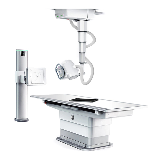
Page 138: Component Identification
Chapter 8: System Hardware Overview Component Identification The Optima XR646 system is made up of several major components and sub-components. Table 8-1 shows the main components. Refer to the individual sections within this chapter for more detailed infor- mation about each component and its related sub-components. - Page 139 Chapter 8: System Hardware Overview Digital Table(p. 8-51) Standard Table(p. 8-59) Chapter 7: Digital Detector(p. 7-1) 5495975-1EN Rev.9 © 2013-2017 General Electric Company. All rights reserved.
-
Page 140: Available Accessories
Chapter 8: System Hardware Overview Available Accessories Table 8-2 Available Options Digital Table Hand Grips and Compression Auto Image Paste Patient Positioner (Option)(p. 8-81) Band(p. 8-71) Radiographic Mobile Tables (Option)(p. 8-82) Wallstand with Extended Arm (Option)(p. 8-83) 5495975-1EN Rev.9 © 2013-2017 General Electric Company. All rights reserved. -
Page 141: Acquisition Workstation
Chapter 8: System Hardware Overview Weight-Bearing Stand (Option)(p. 8-84) Standard Table Hand Grips and Compression Band(p. 8-72) Acquisition Workstation The Acquisition Workstation (Figure 8-1) has its own dedicated computer and image data base. The Workstation applications are based on a graphical, single-screen, mouse and touch screen driven inter- face. -
Page 142: Radiology Control Interface Module (Rcim)
Chapter 8: System Hardware Overview Image display and manipulation Image transfer to other workstations using the DICOM standard Image transfer to a recordable CD or DVD Figure 8-1 Acquisition Workstation Note: Images displayed on the operator console image viewer are not intended for diagnostic use. Radiology Control Interface Module (RCIM) The Radiology Console Interface Module (RCIM) (Figure... - Page 143 Chapter 8: System Hardware Overview Figure 8-2 RCIM Table 8-3 RCIM controls Control Description 1. Emergency Immediately powers down the system (including table, OTS, Stop button wallstand, and x-ray tube) and stops image exposure. To engage: Press the button. To release: Turn the button clockwise (indicated by the arrows on the button) until it stops, then release.
- Page 144 Chapter 8: System Hardware Overview Table 8-3 RCIM controls Control Description 6. X-ray Lights up when x-rays are being emitted, including tube warm Exposure up and QAP. indicator The system beeps as X-rays are produced when the Prep/ Expose button on the Hand-switch is pressed. The tone ends when the exposure is terminated or completed.
-
Page 145: Hand Switch
Chapter 8: System Hardware Overview Hand Switch Exposures are made with the console Hand-switch. The Prep/Expose button on this switch has three positions: OFF, PREPARE, and EXPOSE (Figure 8-3 Table 8-4). Figure 8-3 Console hand-switch and holder Active components for this product: 1. -
Page 146: High Throughput Mode
Chapter 8: System Hardware Overview When the PREPARE function is completed, the READY message appears on screen. 3. Press the Prep/Expose button to the EXPOSE position. The exposure is taken. Note: A procedure must be selected prior to attempting an exposure or an error will occur. 4. -
Page 147: Bar Code Scanner (Option)
Chapter 8: System Hardware Overview Bar Code Scanner (Option) The bar code scanner is a fast, easy way to enter data into the system. The bar code scanner allows you to aim at a printed bar code on paper and scan the information into the system. The printed bar code information comes from a RIS or HIS system through a network. -
Page 148: Overhead Tube Suspension (Ots)
Chapter 8: System Hardware Overview Overhead Tube Suspension (OTS) The Overhead Tube Suspension (OTS) is the positioning device that supports the X-ray tube and OTS User Interface. The OTS has available movement on 5 axes for use in advanced applications. The suspension provides convenient movement and accurate positioning of the equipment. - Page 149 Chapter 8: System Hardware Overview Figure 8-7 OTS User Interface Table 8-6 OTS Function Item Number and Description Description Type 1. Indicator Ready LED Indicates the exposure interlocks are satisfied (green light). The Indicator flashes when the key switch (#19) on the back of OTS Console is in the OVERRIDE position.
- Page 150 Chapter 8: System Hardware Overview Table 8-6 OTS Function Item Number and Description Description Type 3. Indicator Manual Indicates when the system has switched to manual collimation Collimation mode (orange steady light). In this mode, the collimator field of view (FOV) is not limited to the receptor area. If the key switch is in OVERRIDE position, the manual collimation LED flashes (yellow blinking light).
- Page 151 Chapter 8: System Hardware Overview Table 8-6 OTS Function Item Number and Description Description Type 7. Control Tube Releases the lock to allow tube angulation. The lock is active when Angulation you keep pressing the button. The LED is lit when the button is Lock pressed.
- Page 152 Chapter 8: System Hardware Overview Table 8-6 OTS Function Item Number and Description Description Type 12. Control Detent Lock Activates the configured lock detent positions for lateral alignment and SID. The Locks activate when you position the tube in these positions.
- Page 153 Chapter 8: System Hardware Overview Table 8-6 OTS Function Item Number and Description Description Type 17. Control This green light is lit up when all lock release is active except for Transitional tube angulation. Locks Released 18. Control Screen OTS Control Displays and controls exposure settings.
-
Page 154: Ots Control Screen
Chapter 8: System Hardware Overview OTS Control Screen The OTS control screen displays the SID, tube angle, and column rotation. The control screen allows you to change the kV, mAs, receptor, and FOV. The control screen is able to change orientation from horizon- tal to vertical as the OTS is rotated (Figure 8-8). - Page 155 Chapter 8: System Hardware Overview Table 8-7 OTS control screen functions Item Description Displays the SID value in digital table and wallstand applications. The SID display is blank if you have selected table-top mode or if tube angulation exceeds +/- 45 degrees of receptor. Tube Angle Displays the tube angulation in degrees.
-
Page 156: Multiple Wireless Detector Pop-Up Window
Chapter 8: System Hardware Overview Table 8-7 OTS control screen functions Item Description [EXPOSURE HOLD] Appears when there is some condition that prevents an x-ray from being taken, such as the exam room door being open or the tube is not in alignment with the receptor. -
Page 157: Overhead Stationary Rail And Lateral Bridge
Guide bearings maintain alignment of the bridge with the rails and the X-ray table. The Longitudinal Lock Release button on the User Interface controls the motion of the bridge along the rails. The Optima XR646 also has an optional extended bridge available. Refer to Lateral Bridge Lengths(p. -
Page 158: Axes Indicators
Chapter 8: System Hardware Overview Axes Indicators The Optima XR646 shows axes indicators on the carriage (Figure 8-10). These axes markers are color coded to match the release controls on the OTS user interface. The colors for the 3 axes are as follows: ... -
Page 159: Column Rotation
Chapter 8: System Hardware Overview Column Rotation The telescopic column allows you to rotate and angle the tube for better positioning. The telescopic col- umn can be rotated (pivoted) around the vertical axis of the telescopic column 180 degrees. The tele- scopic column automatically locks in each 30 degree position. -
Page 160: Tube And Column Positioning Instructions
Chapter 8: System Hardware Overview Tube and Column Positioning Instructions Adjust the Overhead Tube Suspension (OTS) Position The OTS components can be moved in several directions to properly position the unit during a patient examination. The User Interface is used to control the motions. Use this procedure to learn how to posi- tion the OTS. - Page 161 Chapter 8: System Hardware Overview a) Press and hold the Tube Angulation Lock Release button on the OTS user interface. b) Move the tube unit to the desired angle. c) Release the Tube Angulation Lock Release button. 2. Use the OTS Rotation Detent Release lever to rotate the tube about the vertical axis of the telescopic column.
-
Page 162: Multi-Leaf Collimator
Chapter 8: System Hardware Overview Multi-Leaf Collimator There are 2 kinds of multi-leaf collimator which have the same features and controls. Their very limited difference is the color of interface and light source (Figure 8-13 Table 8-8). The multi-leaf collimator allows you to adjust the radiation field size to the anatomy. The collimator can be used in either the manual or automatic mode. - Page 163 Chapter 8: System Hardware Overview Figure 8-13 Collimator controls Table 8-8 Collimator controls Item Description 1. Spectral Filter Displays the spectral filter selections. The options are 0, 0.1, 0.2 and 0.3 mm Selection of Cu. Press the button to change the filtration. 5495975-1EN Rev.9 8-27 ©...
-
Page 164: Collimator Display
Chapter 8: System Hardware Overview Table 8-8 Collimator controls Item Description 2. Message Displays messages when Exposure Hold is active and providing information concerning the positioner interlocks that are disabling the exposure. If there is no Exposure Hold, displays the size of the collimation field (FOV). Note: Messages shown on collimator display are in English. -
Page 165: Collimator Field And Linear Laser Lights
Check that the FOV is automatically adjusted to the newly selected FOV. To undersize the current FOV, manually turn the collimator knobs. If FOV does not match collima- tor display in either auto or manual mode, contact a GE service representative. Collimator Field and Linear Laser Lights... -
Page 166: Automatic Or Manual Collimator Modes
Chapter 8: System Hardware Overview Figure 8-15 Collimator lights 1. Linear laser light aperture and slider 2. Centering cross light WARNING Laser radiation. Do NOT stare into beam! When you switch on the linear laser light localizer, make sure no person looks directly into the laser to avoid eye injuries or impaired vision. -
Page 167: Rotating The Multi-Leaf Collimator
Chapter 8: System Hardware Overview CAUTION QAP accessory (flat field phantom) must be removed before power off. Figure 8-16 Collimator Locking Lever Rotating the Multi-leaf Collimator For certain exams, such as extremities, you may need to align the collimator field with the anatomy to be exposed. -
Page 168: Digital Wallstand
Chapter 8: System Hardware Overview Digital Wallstand The digital wallstand (Figure 8-18) contains the digital receptor, which can be moved to accomplish dif- ferent radiographic procedures. Figure 8-18 Digital Wallstand 1. Receptor information display 2. Wallstand column 3. Receptor cover 4. - Page 169 Chapter 8: System Hardware Overview Table 8-10 light ring status Light status Description Green System is ready for exposure. Blinking white Override switch is on. System is not ready for exposure. Blinking green Override switch is on. System is ready for exposure. Note: - Light ring is out when Wallstand is powered off.
-
Page 170: Receptor Information Display
Chapter 8: System Hardware Overview Receptor Information Display The receptor information display at the top of the digital wallstand column (Figure 8-19) shows the tilt of the receptor, the currently installed grid, and exposure readiness information. Figure 8-19 Receptor information display 1. -
Page 171: Position The Receptor
Chapter 8: System Hardware Overview Position the Receptor The wallstand receptor placement may be adjusted vertically or tilted. Vertical Adjustment The receptor arm assembly can be moved vertically (Figure 8-20) in one of three ways: Using the Vertical Adjust and receptor Tilt Handle. ... -
Page 172: Vertical Adjust And Detector Tilt Handle
Chapter 8: System Hardware Overview Vertical Adjust and Detector Tilt Handle 1. Grasp the handle and depress the inner switch (Figure 8-21). 2. Move the arm up or down. 3. Release the switch when the desired height is reached. Figure 8-21 Vertical adjust and receptor tilt handle Foot Control The foot control (Figure... -
Page 173: Tilt
Chapter 8: System Hardware Overview Tilt The Digital wallstand receptor can be tilted at any angle within the range of 90 ° (horizontal) to -20° (Figure 8-23). Detents for the receptor tilt are located at 0° (horizontal) and 90° (vertical). Lateral detents on the OTS are active when positioning to the wallstand. - Page 174 Chapter 8: System Hardware Overview Vertical Adjust and Detector Tilt Handle 1. Press and hold a tilt button (Figure 8-25) until desired position is reached. 2. Release the tilt button to stop tilting. Figure 8-25 Tilt buttons on vertical adjust and receptor tilt handle 1.
-
Page 175: Insert Or Remove Grids
Chapter 8: System Hardware Overview CAUTION Patients should be clear of the wallstand when tilting is in process. Insert or Remove Grids Refer to Grids(p. 8-68) for more information about available grids and grid accessories. You have the choice of acquiring images with or without the grid. Grid exams require inserting the proper grid. - Page 176 Chapter 8: System Hardware Overview Grid use in vertical and horizontal position Table 8-11 Grid Use Receptor in Vertical Position Grid Line Orientation Grid in Wallstand Receptor in horizontal Position Grid Line Orientation Grid in Wallstand 5495975-1EN Rev.9 8-40 © 2013-2017 General Electric Company. All rights reserved.
-
Page 177: Positioning Bars And Hand Grips
Chapter 8: System Hardware Overview Positioning Bars and Hand Grips CAUTION Make sure your patient does not use the handgrips or positioning bar for support. CAUTION Be careful of the handgrips that stick out below the wallstand when positioning wheelchair patients under the wallstand. Remove or Attach the Lateral Positioning Bar The digital wallstand is equipped with a lateral positioning bar (Figure... -
Page 178: Ion Chambers
Photo-timing is controlled using three ion chambers similar to the device used in conventional radio- graphic systems. The Optima XR646 wallstand receptor may be equipped with an additional AEC ion chamber. The fourth chamber is more effective when the receptor is used horizontally under a mobile table accessory (Extended arm option). - Page 179 Chapter 8: System Hardware Overview Figure 8-29 Front of wallstand receptor with four ion chambers Fourth ion chamber When the receptor is at or near 0° (vertical), the three main chambers are active and the fourth (lower left) is disabled (Figure 8-30).
-
Page 180: Manual Wallstand
Chapter 8: System Hardware Overview Figure 8-31 Receptor in horizontal configuration The wallstand will determine the angle of the receptor and switch configurations appropriately. When the receptor is at an intermediate angle, only the center chamber (2) will be available for selection from the Image Acquisition screen. - Page 181 Chapter 8: System Hardware Overview 1. Wallstand column 2. Receptor cover 3. Receptor 4. Grid 5. Lateral positioning bar 6. Hand grip 7. Vertical adjust handle Care should be taken when placing lead markers on the receptor to ensure proper visualization on the- Chapter 4: General Information-Identification of Radiographs (p.
-
Page 182: Position The Receptor
Chapter 8: System Hardware Overview Position the Receptor The wallstand receptor placement may be adjusted vertically. Vertical Adjustment The receptor arm assembly can be moved vertically (Figure 8-33) by the Vertical Adjust Handle manually. Figure 8-33 Receptor and arm vertical movement CAUTION Patients should be clear of the wallstand when vertical movement is in process. -
Page 183: Vertical Adjust Handle
Chapter 8: System Hardware Overview Vertical Adjust Handle 1. Grasp the handle and depress the inner switch (Figure 8-34). 2. Move the arm up or down. 3. Release the switch when the desired height is reached. Figure 8-34 Vertical adjust handle Insert or Remove Grids Refer to Grids(p. - Page 184 Chapter 8: System Hardware Overview Figure 8-35 Wallstand Grid (partially inserted) Grid use in vertical position Table 8-12 Grid Use Receptor in Vertical Position Grid Line Orientation Grid in Manual Wallstand 5495975-1EN Rev.9 8-48 © 2013-2017 General Electric Company. All rights reserved.
-
Page 185: Positioning Bars And Hand Grips
Chapter 8: System Hardware Overview Positioning Bars and Hand Grips CAUTION Make sure your patient does not use the hand grips or positioning bar for support. CAUTION Be careful of the hand grips that stick out below the wallstand when positioning wheelchair patients under the wallstand. -
Page 186: Ion Chambers
Chapter 8: System Hardware Overview CAUTION This bar is a hand rest only and is not intended to support a person’s full weight. To avoid falls and potential injuries, do not hang or pull on the bar. CAUTION If the patient pulls on the lateral bar with enough force, the locks may release and the receptor will lower slowly. -
Page 187: Digital Table
Chapter 8: System Hardware Overview Digital Table The digital table includes the digital receptor, or Digital Detector removable grid, foot pedals, and Emer- gency Stop buttons. Figure 8-37 Digital Table Components Components Table 8-13 Digital table components Item Description 1. Tabletop The table dimensions are 240cm (94 in) in length and 93cm (37 in) in width. - Page 188 Chapter 8: System Hardware Overview Table 8-13 Digital table components Item Description 3. Table Top Positioning This pedal allows you to move the table in all directions: longitudinally and Foot Pedals transversely. This is known as a floating tabletop. Press the pedal twice and hold down to move the table top. 4.
- Page 189 Chapter 8: System Hardware Overview Table 8-13 Digital table components Item Description 9. Optical pinch sensor The sensors detect a hand or other body part below the surface of the area table and lock the table movement to prevent injury. The system will sound an audible tone when the finger pinch lock is activated.
-
Page 190: Raise And Lower The Digital Table
Chapter 8: System Hardware Overview Note: The table is equipped with a collision detection system. If contact is made between the tabletop and a foreign object, such as a stool, while lowering the tabletop, the requested motion automat- ically stops until the collision condition is removed. This is accomplished by either clearing the for- eign object from the tabletop movement path or by requesting the reverse movement of the tabletop. -
Page 191: Position The Table Longitudinally And Transversely
Chapter 8: System Hardware Overview 3. Hold the foot pedal down until the desired height is reached. Note: The tabletop automatically stops when it reaches its maximum height of 820 mm (32.0 inches). 4. Remove your foot from the pedal to stop the movement. 5. -
Page 192: Digital Cassette Imaging In Extended Table Detector Tray
Chapter 8: System Hardware Overview WARNING To avoid injury to fingers and hand of patient and operator caused by table move- ment, hands must be kept away from table top edges at all times. Digital Cassette Imaging in Extended Table Detector Tray The Detector is capable of making a digital cassette image while placed in the extended table detector tray. -
Page 193: Grid Loading And Removal
Chapter 8: System Hardware Overview Figure 8-42 Table top positioning foot pedal 2. Remove hands, fingers, or other object from under the table edge. 3. Press the foot pedal (Figure 8-42) two consecutive times (“double-tap”). 4. Hold the foot pedal down and position the table top. Grid Loading and Removal Follow the procedure below for grid loading. - Page 194 Chapter 8: System Hardware Overview 2. Install the grid with the “tube side” label facing up. Refer to Grids(p. 8-68) for more information. 3. Push in the grid tray. 5495975-1EN Rev.9 8-58 © 2013-2017 General Electric Company. All rights reserved.
-
Page 195: Standard Table
Chapter 8: System Hardware Overview Standard Table The standard table includes the digital receptor, or Digital Detector removable grid, foot pedals, and Emergency Stop buttons. Figure 8-43 Standard Table Components Components Table 8-14 Standard Table Components Item Description 1. Tabletop The table dimensions are 2330mm (92 in) in length and 838mm (33 in) in width. - Page 196 Chapter 8: System Hardware Overview Item Description 3. Table Top Positioning This pedal allows you to move the table in all directions: longitudinally and Foot Pedals transversely. This is known as a floating tabletop. Press the pedal twice and hold down to move the table top. 4.
- Page 197 Chapter 8: System Hardware Overview Item Description 10. Hand Grips Two hand grips are optional with the system. These serve to keep the patients' hands away from the tabletop edges and to give patients a feeling of security. The grips are not intended to support the weight of patients.
-
Page 198: Raise And Lower The Standard Table
Chapter 8: System Hardware Overview Note: The table is equipped with a collision detection system. If contact is made between the tabletop and a foreign object, such as a stool, while lowering the tabletop, the requested motion automat- ically stops until the collision condition is removed. This is accomplished by either clearing the for- eign object from the tabletop movement path or by requesting the reverse movement of the tabletop. -
Page 199: Position The Table Longitudinally And Transversely
Chapter 8: System Hardware Overview 3. Hold the foot pedal down until the desired height is reached. Note: The tabletop automatically stops when it reaches its maximum height of 825 mm (32.0 inches). 4. Remove your foot from the pedal to stop the movement. 5. -
Page 200: Digital Cassette Imaging In Extended Table Detector Tray
Chapter 8: System Hardware Overview WARNING When moving the tabletop, be careful of where your and the patient’s fingers are placed. Do not attempt to move the tabletop without using the foot pedals to release the longitudinal and transverse movement locks. WARNING To avoid injury to fingers and hand of patient and operator caused by table move- ment, hands must be kept away from table top edges at all times. -
Page 201: Grid Loading And Removal
Chapter 8: System Hardware Overview 2. Remove hands, fingers, or other object from under the table edge. 3. Press the foot pedal (Figure 8-48) two consecutive times (“double-tap”). 4. Hold the foot pedal down and position the table top. Grid Loading and Removal Follow the procedures below for grid loading. -
Page 202: Non Wireless Configuration
Chapter 8: System Hardware Overview 3. Push in the grid tray. Non Wireless Configuration The FlashPad wireless detector shall be used the following way when system is configured as Non Wire- less Configuration: Tether Cable for non detector tray exposures ... -
Page 203: Detector Management
Chapter 8: System Hardware Overview Detector Management Click Detector Icon on the status bar will launch the Detector Management Window. The Detector Management Window will display the detector serial numbers, calibration status of detector and which Receptor the Detector is connected with. Accessories and Optional Equipment CAUTION For continued safe use of this equipment, use only manufacturer recommended... -
Page 204: Grids
WARNING Accessories should be properly attached to the table and positioned so as not to interfere with system motions. Grids The Optima XR646 system has several grids available for optional purchase. The grids and specifications are described in Table 8-15. - Page 205 Chapter 8: System Hardware Overview Table 8-15 Grid specifications Lines/ Grid Application and Label Range (cm) Orientation Ratio 180cm wallstand grid Wallstand 0 degree 145-245 Vertical 13:1 130cm wallstand grid Wallstand 0 degree 90-190 Vertical 10:1 120cm wallstand grid Wallstand 0 degree 102-146 Vertical 13:1...
- Page 206 Chapter 8: System Hardware Overview Table 8-15 Grid specifications Lines/ Grid Application and Label Range (cm) Orientation Ratio 130cm wallstand horizontal Wallstand 90 degrees 90-190 Horizontal 10:1 grid 100cm Table grid Radiographic Table 90-120 Vertical 12:1 120cm Table grid Radiographic Table 102-146 Vertical 13:1...
-
Page 207: Grid And Accessories Holder
Chapter 8: System Hardware Overview WARNING Handle grids carefully. Dropping a grid may damage it. Place grids in a holder when not in use. Grid and Accessories Holder A holder to store grids and QAP phantoms is available for optional purchase. It is recommended that grids and phantoms be stored in the holder when not in use. -
Page 208: Installation
Chapter 8: System Hardware Overview 1. Adjustment screw 2. Safety screw 3. Lock Installation 1. Depress the lock to release the clamp or hand grip (Figure 8-52). Figure 8-52 Clamp and hand grip released 2. Position the clamp or hand grip; then depress the handle. 3. - Page 209 Chapter 8: System Hardware Overview There are two optional accessories available for the standard table: Abdominal compression band Patient hand grips The compression band and hand grips (Figure 8-54) slide onto the side rails of the tabletop. They can be locked in place in any position along the side rails by locking the hand wheel.
-
Page 210: Installation
Chapter 8: System Hardware Overview Installation Compression Band 1. The compression band can be attached on the standard table top by putting the pulleys inside the slots on the table top aluminum frame on both front and rear sides (Figure 8-55). -
Page 211: Remote Control
Chapter 8: System Hardware Overview Figure 8-56 Clamp and hand grip locked Remote Control The remote control allows you to set the field of view, manually collimate, or enable the collimator lamp, also allows you to move the Wallstand Receptor. Refer to Table 8-16 for details. - Page 212 Chapter 8: System Hardware Overview Figure 8-57 Wallstand Remote Control Sensor Area IMPORTANT! The remote must have a direct line of site to the Wallstand Display. Any people or objects between the remote control and the component will prevent or stop system movement. You may need to move (e.g., stand to the side of the column) in order to re-establish the line of sight.
-
Page 213: Remote Control Functions
Chapter 8: System Hardware Overview Remote Control Functions Figure 8-58 Positioning remote Table 8-16 Positioning remote functions Control Description 1. Remote control A green light indicates that the remote control is emitting a active indicator signal. If the light is on but the component does not move, reposi- tion or re-aim the remote and try again. - Page 214 Chapter 8: System Hardware Overview Table 8-16 Positioning remote functions Control Description 2. Battery Low Indicates when the remote control batteries are low and need indicator replacement. The remote control uses 2 AA (LR6) batteries. 3. FOV small to large Opens the collimator blades to the default positions shown on the OTS control screen in sequence.
- Page 215 Chapter 8: System Hardware Overview Table 8-16 Positioning remote functions Control Description 9. Park Moves the tube to its “park” position when not in use. (Not functional in this product.) 10. Collimator light Turns the collimator light on and off. 11.
-
Page 216: Removing The Batteries
Chapter 8: System Hardware Overview Removing The Batteries The remote control uses 2 AA (LR6) batteries. Remove batteries from the Positioning Remote Control when storing for over two months. Figure 8-59 Removing The Battery Cover 1. Remove the battery cover. 2. -
Page 217: Auto Image Paste Patient Positioner (Option)
Auto Image Paste Patient Positioner (Option) Auto Image Paste is a purchased option for the Optima XR646. The positioner is used to determine the correct Center of Interest (COI) and to protect the patient from the moving receptor during image paste acquisition. -
Page 218: Radiographic Mobile Tables (Option)
Chapter 8: System Hardware Overview Figure 8-63 System cabinet with front open Radiographic Mobile Tables (Option) There are table options available for purchase to use with the Optima XR646 system. Table 8-17 describes each option. Table 8-17 Tables and maximum load capacity... -
Page 219: Wallstand With Extended Arm (Option)
Chapter 8: System Hardware Overview Table 8-17 Tables and maximum load capacity Table Description Maximum Load Capacity Fixed height, mobile, high capacity 295 kg / 650 lbs Fixed height, carbon fiber table 200 kg / 441 lbs Wallstand with Extended Arm (Option) An wallstand with an extended arm is required for taking exposures under a mobile radiographic table (Figure 8-64). -
Page 220: Digital Detector Accessories
Chapter 8: System Hardware Overview Figure 8-64 Extended arm wallstand with mobile table Digital Detector Accessories Cross Table Holders Two detector holders for cross table exams are available. For details, please refer to Chapter 7: Digital Detector-Detector Holder (p. 7-13) ... -
Page 221: Lateral Bridge Lengths
Chapter 8: System Hardware Overview Figure 8-65 Weight-bearing stand Side view Example of use Lateral Bridge Lengths There are several lateral bridge lengths available for different room and system configurations. 2 meters (78.74 inches) bridge (option) 3 meters (118.11 inches) bridge (standard) 5495975-1EN Rev.9 8-85 ©... - Page 222 Chapter 8: System Hardware Overview This page intentionally left blank. 5495975-1EN Rev.9 8-86 © 2013-2017 General Electric Company. All rights reserved.
-
Page 223: Chapter 9: Worklist
Chapter 9: Worklist Chapter 9: Worklist The Worklist is the starting point for patient set up and selecting procedures for acquisition. All exams begin from this screen. The Worklist information and functions are based on DICOM standards. This chapter explains the procedures for entering data into the system and setting up a patient. Overview The Worklist (Figure... - Page 224 Chapter 9: Worklist Figure 9-1 Worklist screen- In Progress Status Figure 9-2 Worklist Screen - Scheduled Status 5495975-1EN Rev.9 © 2013-2017 General Electric Company. All rights reserved.
- Page 225 Chapter 9: Worklist Table 9-1 lists and describes all the functions on the Worklist screen. Table 9-1 Worklist Functions Function Description [Worklist] Worklist Button. Click to go to Worklist Screen [Image Management] Image Management Button. Click to go to Image Management Screen.
- Page 226 Chapter 9: Worklist Table 9-1 Worklist Functions Function Description Patient List Area Shows all procedures scheduled for examinations during a working day. Procedures on the list may be downloaded from the RIS/HIS or may be created locally. The list may be sorted by column, searched, or filtered. Refer to Manage List / Find Procedures (p.
-
Page 227: Patient List Columns
Chapter 9: Worklist Patient List Columns Table 9-2 describes the columns on the Worklist. This information comes from what has been entered in the Patient Information screen. Refer to Overview (p. 9-1) for detailed descriptions of the information pre- sented. Table 9-2 Worklist columns Column Description... -
Page 228: Manage List / Find Procedures
Chapter 9: Worklist Manage List / Find Procedures The Worklist has several features that allow you to find patients and procedures quickly and to organize the list to your preferences. Search, Filters, and Sorting allow you to control the display of the procedures in the Worklist. Search The Search feature finds procedures by column. -
Page 229: Filter List
Chapter 9: Worklist An up-pointing arrow indicates that the column is sorted in ascending order. That is, sorted in alphabetical order or numerical order from smallest to largest. A down-pointing arrow indicates that the column is sorted in descending order. That is, sorted in reverse alphabetical order or numerical order from largest to smallest. - Page 230 Chapter 9: Worklist The filter screen has several options for accepting or rejecting the information from the Worklist. Table 9-3 describes the filter screen functions. Table 9-3 Filter Acceptance/Rejection Buttons Function Description Filter List Filters the Worklist items by system or modality. ...
- Page 231 Chapter 9: Worklist The current date appears in both the From and To fields by default. To select dates from the calendar: Click the [CALENDAR] button. Figure 9-5 Calendar button – The Filter calendar screen appears with the current date selected. Figure 9-6 Filter calendar screen a) Click [ ...
-
Page 232: Refresh
Chapter 9: Worklist If no procedures met all the criteria, the Worklist will be blank. 8. Click [REFRESH] to remove the filter. Refresh The system may be configured to automatically refresh the Worklist with data from the HIS/RIS on a reg- ular basis (such as every 10 minutes). -
Page 233: Select Procedures
Chapter 9: Worklist Select Procedures Use the following processes to select a patient from the Worklist. This process assumes the patient already exists on the system. If the patient is not on the Worklist, you must add the patient first. Refer to Overview (p. -
Page 234: Delete Procedures
Chapter 9: Worklist Delete Procedures You may remove procedures from the Worklist individually or all completed, discontinued, and locally added procedures at once. The [DELETE] button is able to switch between individual delete or delete all. Note: Deleted procedures cannot be recovered or “undeleted.” To switch the button between “Delete”... -
Page 235: Delete Suspended Procedures
Chapter 9: Worklist Delete Suspended Procedures Suspended procedures cannot be deleted unless their status is changed to “Completed” or “Discontin- ued” 1. Select the suspended procedure to delete. A message appears: “The patient entry you are trying to delete is still in progress. Would you like to mark the patient as ‘Completed’... - Page 236 Chapter 9: Worklist Figure 9-10 Add Patient or Patient Information Table 9-4 Patient Information description Function Description Patient Section First Name Identifies the patient’s first name. Middle Name Identifies the patient’s middle name or initials. Last Name Identifies the patient’s last name. Note: Emergency Exams automatically fill this field with a system-generated identification, which is the word “NEW”...
- Page 237 Chapter 9: Worklist Table 9-4 Patient Information description Function Description Birth Date Identifies the patient’s birthday in the format mm/dd/yyyy. If the date is not entered in the correct format, the screen will show the date field in red when [START EXAM] or [SAVE] is clicked. In the above example, the year was entered with only 2 digits (“45”...
- Page 238 Chapter 9: Worklist Table 9-4 Patient Information description Function Description Status Displays the status of the selected exam. When adding a patient, the only option is “Scheduled”. Patient Information options are: Scheduled - The procedure has been added to the Worklist, but the exam has not started.
-
Page 239: Add Patient
Chapter 9: Worklist Add Patient CAUTION Use this procedure to enter the patient’s information into your system. 1. Open the Worklist screen. The Patient Worklist screen appears. 2. Click [ADD PATIENT]. The Add Patient screen appears. 3. Enter the patient information. CAUTION Make sure the patient’s name, ID number, birth date, and gender information are entered correctly. - Page 240 Chapter 9: Worklist This page intentionally left blank. 5495975-1EN Rev.9 9-18 © 2013-2017 General Electric Company. All rights reserved.
-
Page 241: Chapter 10: Image Acquisition
Chapter 10: Image Acquisition Chapter 10: Image Acquisition This section details the process of acquiring images using the Digital Detector or free cassette. Overview The Acquisition screen (Figure 10-1) is where the exam is set up and exposure details are adjusted. This screen appears when you click the [START EXAM], [EMERGENCY EXAM], or [CASSETTE EXAM] buttons on the Worklist or [START EXAM] from the Add Patient screen. - Page 242 Chapter 10: Image Acquisition Table 10-1 Image Acquisition functions Function Description Patient identification Identifies the patient name and patient identification number for the current procedure. [PATIENT INFORMATION] Displays Patient Information screen for the current procedure. Refer to Chapter 9: Worklist-Add or Edit Patient Information (p.
- Page 243 Chapter 10: Image Acquisition Table 10-1 Image Acquisition functions Function Description [DISCONTINUE] Ends the exam when the procedure has been opened but the exam cannot continue. Refer to End Exam (p. 10-31) for more information. Protocol information Identifies the currently selected protocol and view. Also identifies if the protocol is for a Single Energy, Dual Energy, Image Pasting, or VolumeRAD exam.
- Page 244 Chapter 10: Image Acquisition Table 10-1 Image Acquisition functions Function Description Receptor: Selects the receptor for the protocol. The available receptors depend on your system configuration and on the selected protocol. Not all receptors are available for every protocol. In order from left to right, the options are: ...
- Page 245 Chapter 10: Image Acquisition Table 10-1 Image Acquisition functions Function Description Ion Chamber: If in AEC mode, selects the ions chambers to use. (AEC mode only) Note: When in AEC mode, at least one ion chamber must be selected. Any combination of chambers is allowed.
- Page 246 Chapter 10: Image Acquisition Table 10-1 Image Acquisition functions Function Description Adjusts the mAs. The mAs selection is in Renard steps. The available selections are: 0.1, 0.12, 0.16, 0.20, 0.25, 0.32, 0.40, 0.50, 0.64, 0.80, 1.0, 1.25, 1.6, 2.0, 2.5, 3.2, 4.0, 5.0, 6.4, 8.0, 10.0, 12.5, 16.0, 20.0, 25.0, 32.0, 40.0, 50.0, 64.0, 80.0, 100.0, 125.0, 128.0, 160.0, 200.0, 250.0, 256.0, 320.0, 400.0, 500.0, 512.0.
- Page 247 Chapter 10: Image Acquisition Table 10-1 Image Acquisition functions Function Description Patient Position: Selects the patient position relative to the receptor. The available options change if the currently selected protocol view is for paired or non-paired anatomy. For paired anatomy, the available options are: ...
-
Page 248: Patient Dose Reporting
Chapter 10: Image Acquisition Table 10-1 Image Acquisition functions Function Description [WARM TUBE] Displays the tube warming status. When the yellow alert icon is present, the tube must be warmed before images may be acquired. Note: Because the tube warming procedure produces x- rays, it cannot be performed when an exam is open. -
Page 249: Dose Reporting Tool
Chapter 10: Image Acquisition Note: The radiation dose is inversely proportional to the square of the focal sport to skin distance. In manual override mode and Free Cassette mode, the SID displayed on the collimator is used to calcu- late the DAP. Dose Reporting Tool The Dose Reporting Tool allows a user to export dose relevant data within a specific time frame. - Page 250 Chapter 10: Image Acquisition Figure 10-3 Time Frame 5. Remove CD/USB while export is complete. 5495975-1EN Rev.9 10-10 © 2013-2017 General Electric Company. All rights reserved.
-
Page 251: Re-Start Completed Or Discontinued Exams
Chapter 10: Image Acquisition Figure 10-4 Sample Report Re-start Completed or Discontinued Exams Procedures with a Status of “Completed” or “Discontinued” cannot be re-opened. However, you may cre- ate a new exam or append the existing exam. 1. Select the procedure(s) from the Worklist. 2. -
Page 252: Resume Suspended Exams
Chapter 10: Image Acquisition Figure 10-5 Start a discontinued or completed exam message 4. Click the button of the action to perform. [APPEND EXAM] creates a new series within the existing exam and opens the Select Protocols screen. Note: The new exam will be placed under the same accession number as a new series. Check your facil- ity’s conformance standards before selecting this option because it may effect HIS/RIS or PACS formats. - Page 253 Chapter 10: Image Acquisition The select protocols screen is divided into two halves: Available Protocols on the left and Selected Proto- cols on the right. Available Protocols lists all the protocols currently listed in the database, categorized by anatomical region: for example, head, chest, spine, and abdomen.
-
Page 254: Automatic Protocol Assist (Option)
Chapter 10: Image Acquisition Figure 10-8 Selected exams The category and exam name appear in the Selected Protocols list. 4. Click the exam again to de-select it. The category and exam name are removed from the Selected Protocols list. 5. -
Page 255: Conduct A Table Exam
Chapter 10: Image Acquisition Figure 10-9 Add Exam screen Conduct a Table Exam This section describes the adjustments required when conducting a table exam. Refer to Chapter 5: Quick Steps-General Acquisition (p. 5-4) for an overview of the entire acquisition pro- cess. - Page 256 Chapter 10: Image Acquisition CAUTION It is critical to select the proper patient size on the Acquisition screen. The incor- rect Patient Size may result in an unnecessarily large radiation dose or multiple exposures. 3. Select the Table Receptor, if necessary (Figure 10-10).
-
Page 257: Conduct A Wallstand Exam
Chapter 10: Image Acquisition 11. Have the patient suspend respiration, if required. 12. Make exposure using the hand-switch. The image appears on Image Viewer screen. Conduct a Wallstand Exam This section describes the adjustments required when conducting a wallstand exam. Refer to Chapter 5: Quick Steps-General Acquisition (p. - Page 258 Chapter 10: Image Acquisition Figure 10-13 Grid and SID status An alert icon appears if the current Grid or SID is not in the recommended status for the technique. A checkmark appears if the current Grid or SID is in the recommended status for the technique. ...
-
Page 259: Conduct A Table Top Exam
Chapter 10: Image Acquisition Conduct a Table Top Exam This section describes the adjustments required to conduct a digital exposure outside of wallstand detec- tor tray or table docked position. Follow this process to conduct an exam with the detector outside of wallstand detector tray or table docked position. -
Page 260: Conduct A Cassette Exam
Chapter 10: Image Acquisition Note: If you are performing with more than one detector, please avoid the detectors overlapped position when taking exposure. Because, with one detector placed in the table housing, when another detector is positioned on the tabletop to take exam, the Exposure Inhibition may happen when the two detectors overlapped. - Page 261 Chapter 10: Image Acquisition Figure 10-15 Cassette exam Acquisition screen Follow this process to conduct a Cassette Exam. 1. Click [CASSETTE EXAM] from the bottom of the Worklist screen. Note: Because a cassette exam does not use digital image storage, you do not select procedures from the Worklist.
- Page 262 Chapter 10: Image Acquisition 4. Select the Exam and View to perform from the protocol list. 5. Make technique adjustments as necessary for the appropriate body part being imaged: kV and mAs Note: For film and CR cassette work, use your site’s routine techniques as with any other Xray system. For ease of use, these techniques can be programmed into the protocol database.
-
Page 263: Conduct An Emergency Exam
Chapter 10: Image Acquisition Conduct an Emergency Exam Emergency Exam is a function that allows a patient to be x-rayed without selecting the patient from the Worklist or adding the patient to the Worklist. Figure 10-17 Emergency Exam button Emergency Exam is used in the following situations: ... -
Page 264: Automatic Exposure Control (Aec)
Chapter 10: Image Acquisition Automatic Exposure Control (AEC) The Automatic Exposure Control automatically terminates an X-ray exposure to produce optimum qual- ity images. AEC automatically compensates for changes in patient thickness, opacity, and different tech- nique factors of mA, kVp, and SID. Proper patient positioning is very important. In extreme cases of misalignment, some radiation bypasses the patient and ends the exposure prematurely, causing under- exposed images. - Page 265 Chapter 10: Image Acquisition After the exposure has been completed, the console automatically displays the exposure time (mSec) and mAs values (Figure 10-19). Figure 10-19 Example AEC exposure completed (normal operation) The Applications software sets two limits for AEC operation: 512 is the maximum mAs. 2 seconds (2000 milliseconds) is the maximum exposure time.
-
Page 266: Ion Chamber Detectors
Chapter 10: Image Acquisition Ion Chamber Detectors Ion Chamber Detectors have three sensing areas (Figure 10-20). Sensing Area 2 is located at the center of the X-ray beam. While Area 1 and Area 3 can be selected to cover an exposure of two symmetrical parts of the body, such as the lungs or the kidneys, care should be taken to center the patient and receptor areas accordingly. -
Page 267: Area 2
Chapter 10: Image Acquisition If the patient is improperly positioned and the sensing areas are exposed to direct radiation, the photo timed exposures will be too short and the films underexposed. The opposite is true if the patient’s tho- racic spine or sternum are positioned over the sensing areas. Note: Areas 1 and/or 3 are to be used with full-sized fields of 10x12 inches (254x305mm) or larger. - Page 268 Chapter 10: Image Acquisition Table 10-2 Detector sensing areas Area(s) Selected Application Patient Positioning Area 2 Controls the exposure for an The patient’s area of interest is in area of interest at the center of the X-ray field center. the X-ray field. Area 1 Controls the exposure for an The patient’s area of interest is in...
-
Page 269: Aec Limitation Messages
Chapter 10: Image Acquisition AEC Limitation Messages The AEC feature optimizes patient images and helps you to obtain precise exposures. Many default tech- niques are AEC based in order to optimize image processing. The exposure time and mAs are automati- cally selected when you are in AEC mode, producing uniform quality images. -
Page 270: Acquire Aec Images
Chapter 10: Image Acquisition Acquire AEC Images Acquiring images in the AEC mode requires precise light alignment and patient positioning. WARNING Collimation must be active over the AEC chambers being used or FIXED mode must be used in order to prevent possible patient over-exposure. Use this process to produce images with the AEC feature. -
Page 271: End Exam
Chapter 10: Image Acquisition 13. Make the exposure. 14. If the AEC Back-up Reached message appears: Click [OK]. The message closes. 15. Observe technique settings and continue exam. End Exam There are several ways to end an exam: Suspend, Close, and Discontinue. Each method is used for a spe- cific purpose to cover a variety of different situations. -
Page 272: Image Recovery
Chapter 10: Image Acquisition The available reasons are: Doctor cancelled procedure Patient pregnant Equipment failure Change of procedure for correct charging Incorrect procedure ordered Duplicate order Patient allergic to media/contrast Nursing unit cancel ... - Page 273 Chapter 10: Image Acquisition Figure 10-24 Image Recovery confirmation During this time, do not remove the active detector from the table or wallstand. If in wireless mode place the detector within a strong wireless signal area – do not power off. Select the ‘Recover Image’ button to continue image recovery.
-
Page 274: Chapter 11: Image Viewer
Chapter 11: Image Viewer Chapter 11: Image Viewer The Image Viewer screen (Figure 11-1) appears once an exposure is taken in a started exam or when an image series is chosen from the Image Management screen for review. This screen is where images are adjusted and viewed. - Page 275 Chapter 11: Image Viewer Figure 11-1 Image Viewer screen Table 11-1 Image Viewer screen functions Function Description Patient identification Identifies the Patient Name and Patient ID as entered on the Patient Information screen. Exam / Series Collapsible panel that contains a list of exams and series within the exams.
- Page 276 Chapter 11: Image Viewer Table 11-1 Image Viewer screen functions Function Description Viewer Display Collapsible panel that allows you to adjust how many images are viewed at once and image size. Refer to Change Viewing Format and Size (p. 11-6) for more information.
-
Page 277: Tool Selection List
Chapter 11: Image Viewer Table 11-1 Image Viewer screen functions Function Description Image database size Shows how many images are currently saved to the local database and approximately how many more images the database can accommodate. [TRANSFER LOG] Shows a list of transferred exams and their destinations. Refer to Chapter 12: Image Management-Copy Exams and Images (p. -
Page 278: Select Images
Chapter 11: Image Viewer Select Images The Images-Processed panel in the Image Tools palette (Figure 9-3) allows you to select which exam or series of images to view. Note: When viewing or adjusting images from a completed exam, always work with processed images. Figure 11-3 Images-Processed panel The Images panel shows previews of all images in the selected series. -
Page 279: Change Viewing Format And Size
Chapter 11: Image Viewer Change Viewing Format and Size The Format/Zoom panel in the Image Tools palette controls how many images appear in the Image Viewer screen at one time and adjust the magnification of each image. The Display Format panel (Figure 11-4) allows you to view up to 9 images at one time. -
Page 280: Adjust Images
Chapter 11: Image Viewer Table 11-2 Zoom tool descriptions Tool Description True Size Shows the image in the exact size it was acquired from the receptor (one centimeter on the receptor equals one centimeter on screen). Adjust Images The Image Display Tools panel (Figure 11-6) contains the tools to flip, rotate, adjust brightness, adjust contrast, invert, and apply windowing to the selected image. - Page 281 Chapter 11: Image Viewer Table 11-3 Image Display Tools descriptions Tool Description Brightness Lightens or darkens the selected image. Move the slider right for a lighter image. Move the slider left for a darker image. Invert Reverses light and dark areas of the selected image. Windowing Applies windowing to the selected image.
-
Page 282: Annotate And Mask Images
Chapter 11: Image Viewer Table 11-3 Image Display Tools descriptions Tool Description Restore Image Removes all adjustments and returns the selected image to its original state. Annotate and Mask Images The Annotations/Mask panel contains the tools to annotate images. Table 11-4 describes the tools and their functions. - Page 283 Chapter 11: Image Viewer Table 11-4 Annotations/Mask tool descriptions Tool Description Line Places a line on the image that you may re-size, move, or angle. Line specifications are shown in the User Measurements annotation at the bottom right corner of the image. Ellipse Places an ellipse (circle or oval) on the image that you may re-size, move, or re-shape.
- Page 284 Chapter 11: Image Viewer Table 11-4 Annotations/Mask tool descriptions Tool Description Full Places all available system annotation on the image. Patient information (top left corner) exam date and patient identification Study information (top left corner) exam identification Series information (top left corner) series identification ...
-
Page 285: Customize System Annotations
Chapter 11: Image Viewer Table 11-4 Annotations/Mask tool descriptions Tool Description Manual Manually adjusts the image shutter. Shutter Collimation is detected using image-based processing. In some cases, the FOV detected by the system does not match the actual exposed FOV. Use the Manual Shutter tool to correct this. Note: This function is only available when the image is open in a live exam or for re-processed images. -
Page 286: Add Image Annotations
– N (Normal: default setting) – +1 – +2 – +3 (largest) Note: GE Service personnel can change the default Font Size at your request. 5. Click [OK]. [CANCEL] closes the screen and leaves the selections unchanged. Add Image Annotations Note: All image annotations initially appear in the same place (center of image) and are the same shape, size, or angle. -
Page 287: Delete Image Annotations
Chapter 11: Image Viewer Table 11-5 Image annotation instructions Tool Instructions User Select an annotation from the list or click in the “CUSTOM” text area Annotation of the Text Annotation screen. Type your comment. Click [OK]. To move: Click and drag by the red square on the top left corner of the text box. -
Page 288: Adjust Image Shutter (Crop Image)
Chapter 11: Image Viewer Adjust Image Shutter (Crop Image) The system has the ability to detect the collimated edges of the image and may apply shutters to mask the collimated areas. Refer to Automatic Shutter (p. 11-16) for more information. The Manual Shutter function allows you adjust the automatically applied (default) shutter for viewing and printing. -
Page 289: Automatic Shutter
Chapter 11: Image Viewer Figure 11-10 Close up of manual shutter 3. Click and drag the red corner handles or the yellow side lines to the desired shape and size. Note: Any image annotations (line, Cobb, ellipse, R/L marker) that are outside of the yellow lines (visible image area) will be lost when the exam is closed. -
Page 290: Re-Process Images
This allows the system to provide a shuttered image on the viewer regardless of where the collimated image edges lie on the receptor. The Optima XR646 is able to detect collimation edges present in an x-ray radiograph. This allows the sys- tem to provide a shuttered image on the viewer. - Page 291 Chapter 11: Image Viewer Figure 11-13 Image Tools palette – Image Re-processing panel Table 11-6 Reprocessing tool descriptions Function Description Current Shows the current image processing settings. Anatomy Changes the anatomical region. View Changes the view. Image Type Displays the image type of the acquisition. Images cannot be re-processed with a different image type than originally acquired.
-
Page 292: Deviation Index (Di)
Chapter 11: Image Viewer Table 11-6 Reprocessing tool descriptions Function Description Look Changes the processing look. Looks are the way an image is processed to be viewed by a radiologist for interpretation. Looks are pre-defined combinations of brightness, contrast, edge enhancement, and tissue equalization. - Page 293 Chapter 11: Image Viewer Figure 11-14 DI graphical display 1. DI Control Limit 2. DI Control Range Suggestion 3. Current DI for the selected image Table 11-7 Examples of visual range DI displays Display Description Low DI = Out of Desired range [lower than Target Exposure Index] Low DI = Acceptable Range [Slightly lower than Target Exposure Index]...
-
Page 294: Corrective Actions
Chapter 11: Image Viewer Corrective Actions If DI values become consistently outside of the acceptable range, the user may consider following cor- rective actions depending on Image quality and Patient Entrance Dose after confirming that imaging conditions are appropriate (e.g. collimation and shuttering, unusual body habitus, presence of prosthet- ics, shielding, AEC): (A) Image quality and Patient Entrance Dose are acceptable - Adjust ‘Customer Target EI’... -
Page 295: Change Pointer Controls
Chapter 11: Image Viewer Change Pointer Controls The pointer control buttons (Figure 11-15) change the action of the pointer when it is clicked and dragged on an image. Figure 11-15 Pointer control buttons The pointer controls allow you to perform other functions that are not available in any other tool panel. Follow this process to change the pointer controls. -
Page 296: Apply Quality Check Indicator (Auto Tag)
(more horizontally) the brightness will change more than the contrast. There is an option to enable “speed” control for this function that sets how fast the brightness and contrast changes on the image. GE Service personnel enable the option and it is configurable through preferences. Refer to Chapter 15: Preferences-Image Viewer (p. -
Page 297: Repeat/Reject Analysis (Rra)
Chapter 11: Image Viewer Repeat/Reject Analysis (RRA) The Repeat/Reject Analysis (RRA) feature, if enabled, provides a way for you to categorize and provide a reason for images that you have removed the quality check indicator from. RRA data is saved on the system for 100 days and may be exported as a report. Note: Refer to Chapter 13: Advanced Applications-Repeat/Reject Analysis (RRA) (p. - Page 298 Chapter 11: Image Viewer Figure 11-17 Classify Image and Select Repeat Reason Depending on the RRA Preferences selection, the Repeat/Reject Confirmation screen (Figure 11-18) may appear when you close the exam. The screen displays the following information: The number of Images Accepted (images with the quality indicator mark) in the exam ...
-
Page 299: Print Images
Chapter 11: Image Viewer Figure 11-18 RRA confirmation on exam close Print Images Images can be printed from the system in two ways: Auto Print and Manual Print. Auto Print The system can be configured to perform an automatic print upon closure of the exam. Preferences are accessed from the Utilities screen. -
Page 300: Quick Print
Chapter 11: Image Viewer Figure 11-19 Manual Print Buttons- Quick Print and Film Composer Quick Print Follow this process to print a single image. 1. Select the image from the Images tool panel, if necessary. 2. Click [QUICK PRINT]. The Print Images screen appears, as shown in Figure 11-21. - Page 301 Chapter 11: Image Viewer Figure 11-20 Example of Print Preview with incorrect settings 5. Click [PRINT] to print the image. [CANCEL] closes the Print Images screen without printing and returns you to the Image Viewer screen. 5495975-1EN Rev.9 11-28 ©...
- Page 302 Chapter 11: Image Viewer Figure 11-21 Print Images screen Table 11-9 Print Images field description Field Description Printer Lists all available printers configured for your system. Orientation Selects vertical or horizontal orientation of the image on film or paper. Available options are: ...
- Page 303 Chapter 11: Image Viewer Table 11-9 Print Images field description Field Description Magnification Only available if Reduced Size is selected for the Print Mode. Format Selects the print format. Available options are: Standard 35 mm 40 mm Media Size Shows the available sizes that are configured for the selected printer.
-
Page 304: Print Multiple Images
Chapter 11: Image Viewer Print Multiple Images Follow this process to print multiple images. 1. Click [FILM COMPOSER]. The Film Composer screen (Figure 11-22) appears. Figure 11-22 Film Composer screen - after images are added 2. Select the number of images you want to appear on a sheet. ... -
Page 305: Print Multiple Patient Images (Option)
Chapter 11: Image Viewer Figure 11-23 Images - Processed panel 4. Use the buttons to confirm and adjust the print settings. Click [PREVIEW] to see how the images are positioned on the sheet. Click [CLEAR SHEET] to remove images from the currently displayed sheet. ... - Page 306 Chapter 11: Image Viewer 2. Select exams you want to print. the “Viewer” button change to “Print”. 3. Click “Print” button, and then Confirmation box pops up. Click “OK” to continue. Click “Cancel” to cancel the print job and returns to last screen. 5495975-1EN Rev.9 11-33 ©...
-
Page 307: Orthopedic Magnification (Option)
Factor (CMF) through the Services User Interface. The CMF is the amount of magnification applied to all Orthopedic Magnification functions. Only GE Service personnel are able to change the CMF. Each facility determines the changes to the default CMF. Consult your Medical Physicist for assis- tance on dose concerns. -
Page 308: Send Images
Chapter 11: Image Viewer Send Images If Auto Send is enabled, acquired images are automatically sent to a pre-determined location on exam close. Refer to Chapter 15: Preferences-Auto Send (Auto Push) (p. 15-24) for information on configuring Auto Send. Save Changes to Images You have the option to save or discard the changes you have made to images when you close the Image Viewer screen or end the exam. - Page 309 Chapter 11: Image Viewer This page intentionally left blank. 5495975-1EN Rev.9 11-36 © 2013-2017 General Electric Company. All rights reserved.
-
Page 310: Image Processing
Chapter 12: Image Management Chapter 12: Image Management Image Processing The Image Processing preferences allow you to view the settings of default factory looks or to create up to five (5) custom looks. Image Processing Preferences also allow you to change which look is the default for the anatomical view. - Page 311 Chapter 12: Image Management Figure 12-2 Image Management screen 1. Selected exam 2. Series in exam 3. Image detail button 4. Images in selected series 5. Preview of selected image 5495975-1EN Rev.9 12-2 © 2013-2017 General Electric Company. All rights reserved.
- Page 312 Guide – Allows for viewing of the Operator Manual. This is installed by GE Service Personnel. PACS Test Images – Loads a set of calibration images that are used to test the quality of images sent to PACS or printers.
- Page 313 Chapter 12: Image Management Table 12-1 Image Management screen functions Function Description Exam, series, and images list Lists the images saved in the local database categorized by exams and series. The following information is displayed: Exams - the exams saved in the local database ...
-
Page 314: View Patient Information
Chapter 12: Image Management View Patient Information When accessed from the Image Management screen, the Patient Information screen displays exam information about the acquired images in the lower left corner (Figure 12-3). All other patient information is as described in Chapter 9: Worklist-Add or Edit Patient Information (1). -
Page 315: Search List
Chapter 12: Image Management Note: If the exams are being viewed on a computer that has the DICOM viewer installed, images may be viewed directly from the disk. Search List The Search feature finds procedures by column. Figure 12-4 Search by column drop-down list 1. -
Page 316: Open Exams And Images
Chapter 12: Image Management Figure 12-5 Column with ascending sort Open Exams and Images Follow this process to open exams and images for viewing. 1. Click the [+] button to the left of the exam name to open it. The series for the exam expands below the exam. 2. -
Page 317: Copy Images To Another Exam
Chapter 12: Image Management To see the status of the exams being copied, click [TRANSFER LOG] at the bottom of the Image Man- agement screen. The Transfer Log screen (Figure 12-6) appears. 5. Click [CLOSE] to close the screen and return to the Image Management screen. Figure 12-6 Transfer Log screen Copy Images to Another Exam This process is used to copy images from one exam to another. - Page 318 Chapter 12: Image Management The Copy Exam screen appears. The Copy Exam screen shows all Worklist entries with the status of “Scheduled”, “Discontinued”, or “Suspended”. 4. Search or Filter the exam list to locate the destination exam. 5. Select the exam where you want the images copied to. 6.
- Page 319 Chapter 12: Image Management Note: Pressing the Eject button on the workstation PC does not open the disk tray. When working on the Image Management screen, always use the Eject option from the [CD1] drop-down list (Figure 12-7). Figure 12-7 CD 1 button drop down list 2.
-
Page 320: Delete Exams, Series, Or Images
Chapter 12: Image Management 9. Remove the disk. 10. Label the disk and store in a safe place. Delete Exams, Series, or Images Exams, series, and images may be deleted from the local database from the Image Management screen. Follow this process to delete exams, series, and images. 1. -
Page 321: Unlock Exams
Chapter 12: Image Management The [LOCK] button changes to [UNLOCK]. Unlock Exams Follow this process to unlock exams so that they may be deleted. 1. Select the locked exams. The Unlock button becomes active. 2. Click [UNLOCK]. The lock icon is removed from the status column of the selected exams. ... - Page 322 Chapter 12: Image Management A message appears: “The selected exams will be copied without patient identification. The originals will not be deleted.” 3. Click [OK]. The Image Management screen updates with copied, anonymous exams. 5495975-1EN Rev.9 12-13 © 2013-2017 General Electric Company. All rights reserved.
- Page 323 Chapter 12: Image Management This page intentionally left blank. 5495975-1EN Rev.9 12-14 © 2013-2017 General Electric Company. All rights reserved.
-
Page 324: Dual Energy
Chapter 13: Advanced Applications Chapter 13: Advanced Applications Dual Energy Overview Dual Energy (DE) is an optional imaging technique in which a low-kVp image and a high-kVp image are acquired in rapid succession. The acquired images are processed to create a soft-tissue image and a bone image, which are provided in addition to the standard (high-kVp for chest DE and low-kVp for abdo- men) image. -
Page 325: General Guidelines
Chapter 13: Advanced Applications General Guidelines Dual Energy acquisition and processing algorithms are optimized for Chest AP/PA and Abdomen AP/PA on adult patients. Use of Dual Energy imaging on other anatomical views and/or pediatric patients may result in degraded image quality. For Dual Energy acquisitions, it is particularly important for the patient not to move or breathe during the exposure. -
Page 326: Grid
Chapter 13: Advanced Applications Grid The processing algorithms are optimized for chest imaging with grid IN. Removing the grid may degrade image quality. Patient Dose Assuming correct selection of patient-size setting, the entrance dose (air-kerma) of the low-kVp exposure should be equivalent to that of the high-kVp exposure. For a typical two-view chest exam, the Lateral view dose is much higher than that of the PA or AP view. -
Page 327: Copper Filtration
Chapter 13: Advanced Applications Low kVp Can be set anywhere between 70 and 85. In general, a lower low-kVp (default is 80) will result in better “tissue cancellation”. However, for large patients, slightly increasing the low kVp (e.g., to 85) may improve x-ray penetration and consequently improve the noise characteristics of the resulting soft-tissue and bone images. -
Page 328: Orthopedic Magnification
Factor (CMF) through the Services User Interface. The CMF is the amount of magnification applied to all Orthopedic Magnification functions. Only GE Service personnel are able to change the CMF. Only processed images will have Orthopedic Magnification applied. The raw images remain as acquired. -
Page 329: Print Multiple Images
Chapter 13: Advanced Applications Figure 13-2 Print Images screen with Orthopedic Print Mode selected Print Multiple Images Follow this process to print multiple images through the Film Composer with Orthopedic Magnification applied. 1. Select the series to print. 2. Click [FILM MANAGER]. ... -
Page 330: Orthopedic Magnification Preferences
Chapter 13: Advanced Applications Orthopedic Magnification Preferences The following sections describe the preferences that are available to configure Orthopedic Magnification functions. Refer to Chapter 15: Preferences for more information about configuring other preferences. Configure Default Print Settings and Auto Print You may select Orthopedic Print as a default print setting for manual printing and auto print. -
Page 331: Repeat/Reject Analysis (Rra)
Chapter 13: Advanced Applications Repeat/Reject Analysis (RRA) RRA is an option that allows classification and tracking of images that are considered unsuitable for diagnostic purposes. The repeated and rejected images are retained on the system and can be exported at any time. The system allows periodic generation of a statistical RRA report with Clinical Repeat Rate. The Auto Tag function must be enabled (ON) in order to enable RRA on the system. -
Page 332: Rra Confirmation Screen
Chapter 13: Advanced Applications 6. Configure the preset names for the Operators, if necessary. Refer to Chapter 15: Preferences-Preset Names (p. 15-19). RRA Confirmation Screen The RRA Confirmation Screen selection controls the presence of the confirmation screen displayed on the viewer when the exam is closed. This screen provides a summary of the RRA classified images in the exam. - Page 333 Chapter 13: Advanced Applications Figure 13-6 Example of RRA Report (html) Figure 13-7 Example of detailed RRA data (partial screen) You can create and export RRA reports from the RRA Reporting Tool screen shown in Figure 13-8. 5495975-1EN Rev.9 13-10 ©...
- Page 334 Chapter 13: Advanced Applications Figure 13-8 RRA reporting tool screen Table 13-1 Repeat/Reject Analysis functions Function Description Previous export Provides the date and time of the last RRA export and the time period covered information in the last export. The text is as follows: The last RRA Export was performed on (date) at (time) with a period of analysis from (date) at (time) to (date) at (time).
-
Page 335: Not Enough Space To Save Rra Images
Chapter 13: Advanced Applications Follow this process to export RRA data: 1. On the Worklist screen, click [UTILITIES]. 2. Select RRA Reporting Tool [START] button. 3. Set the From date and time 4. Set the To date and time 5. Insert a blank CD-R into the disk tray or connect a USB (minimum 64 MB) device to a USB port on the acquisition workstation. -
Page 336: Auto Image Paste
Chapter 13: Advanced Applications 6. Wait for the export to complete. 7. Remove the disk or USB device. 8. Insert a new disk or connect a new USB device. 9. Click [RESET TO LAST EXPORT] to change the From date and time. 10. -
Page 337: Auto Image Paste Patient Positioner With Integrated Foot Step (For Wallstand)
Chapter 13: Advanced Applications Figure 13-10 Overall setup for Auto Image Paste at the wallstand 1. X-ray tube 2. Patient Positioner 3. Riser 4. Wallstand Auto Image Paste Patient Positioner with Integrated Foot Step (for Wallstand) The patient positioner (Figure 13-11) is used in wallstand exams to determine the correct Center of Inter- est (COI) and to accurately re-construct images. - Page 338 Chapter 13: Advanced Applications Figure 13-11 Patient positioner with Integrated Foot Step 1. Lateral positioning bars 2. Mylar backing 3. Floor locks (one on each side) 4. Foot Step Table 13-2 Symbols on Patient Positioner Symbol Description Hand crushing hazard. This symbol indicates that serious injury to the hand may occur.
-
Page 339: Lock Positioner In Place
Chapter 13: Advanced Applications Symbol Description Lock - Engaged Unlock - Disengaged Lock Release- Pull pin to release lock and move lateral positioning bar Lock Positioner in Place The positioner locks into place in front of the wallstand receptor. Locking the positioner ensures that it is at the appropriate distance from the receptor, that it will not move during acquisition, and that the patient does not fall. - Page 340 Chapter 13: Advanced Applications Figure 13-13 Positioner and receiving hole Receiving Hole 2. Press the Lock Lever down so that the pin goes into the hole. Press down enough to lock up (Figure 13-14). Figure 13-14 Lock Lever pressed down and in lock position 3.
-
Page 341: Move Lateral Positioning Bars
Chapter 13: Advanced Applications Move Lateral Positioning Bars 1. Hold the Lateral Positioning Bar and pull the lock release to adjust the vertical placement. (Figure 13-15). Figure 13-15 Lock release in the unlocked position 2. Move the lateral positioning bar to the desired height and then release, thus the positioning bar will be locked. -
Page 342: Conduct Wallstand Exam
Chapter 13: Advanced Applications b) Select the Exam (Spine or Leg). 4. Click [ACCEPT]. Figure 13-16 Protocol selection for Auto Image Paste Continue with Conduct Wallstand Exam (p. 13-19). Conduct Wallstand Exam Follow this process to conduct an Auto Image Paste exam at the wallstand. 1. - Page 343 Chapter 13: Advanced Applications Figure 13-17 Acquisition screen for Auto Image Paste—before acquisition 3. Select the Patient Size. 4. Adjust the technique on the Acquisition screen. Note: Settings are applied to all acquired images. There is no “asymmetric collimation” selection. ...
- Page 344 Chapter 13: Advanced Applications Figure 13-18 COI on OTS control screen 9. Activate the detents. 10. Instruct the patient to close his or her eyes. 11. Turn on the collimator light and Make sure the laser radiation is ON. WARNING Laser radiation.
- Page 345 Chapter 13: Advanced Applications Figure 13-19 Define top of coverage area Head button 14. Aim laser light at the bottom of the desired image field (Figure 13-20). You may do this by either angulating the tube or by keeping the tube at 90° and moving the column vertically.
- Page 346 Chapter 13: Advanced Applications Figure 13-22 Collimate for exam Note: Auto Image Paste registration can cause narrowing of the field. Do not collimate too tightly, because the outer 1-2 cm may be collimated in the pasted image. 17. Press the [SET] button (Figure 13-23) on the OTS control screen when finished.
-
Page 347: Alternate Auto Image Paste Acquisition Workflows
Chapter 13: Advanced Applications Figure 13-25 Image Status on Acquisition screen The sub-images appear on the Viewer screen as they are acquired and a pasted image appears approximately 10 seconds later. 19. Continue with Chapter 13: Advanced Applications-Image Viewer (p. 13-25) to view, re-paste, or pro- cess images. -
Page 348: Image Viewer
Chapter 13: Advanced Applications 4. Set the HEAD and FOOT positions with the tube stand at approximately the midpoint of what will be the tube travel (typically knee height of the patient) using the laser light/tube angle method. 5. Set the HEAD center point, using the laser light, slightly HIGHER than normal (i.e., 5cm—or 2 in— above the top of the anatomy you intend to acquire—e.g. -
Page 349: View Pasted Composite Image
Chapter 13: Advanced Applications View Pasted Composite Image The pasted composite image (Figure 13-26) appears automatically after acquisition and processing is complete. Figure 13-26 Image Viewer screen with pasted composite image The registration markers (brackets) show the general area of pasted overlap (Figure 13-27). -
Page 350: Re-Process Images
Chapter 13: Advanced Applications Figure 13-28 Exam/Series panel Re-Process Images The Image Processing tab of the Image Tools panel (Figure 13-29) contains the tools to re-process and repaste sub-images and pasted images. Refer to Change Looks Processing (Vertical Equalization) (p. 13-30) for more information. - Page 351 Chapter 13: Advanced Applications Figure 13-30 Re-paste button The Re-pasting screen shows two sets of images. The left half shows the selected pasting region (the overlapped area between 2 sub-images). The left half is also the work area where you set the alignment. The right half shows a preview of the pasted image.
- Page 352 Chapter 13: Advanced Applications Figure 13-32 Select region drop-down list. 4. Click and drag on a red cross-hair to move it (Figure 13-33). Figure 13-33 Cross-hairs 5. Place the cross-hairs at the same anatomical reference point on image. The mouse control buttons (Figure 13-34) change the action of the cursor when used on images.
-
Page 353: Change Looks Processing (Vertical Equalization)
Chapter 13: Advanced Applications Figure 13-35 Preview and Apply to Image buttons 8. When satisfied with image alignment, click [APPLY TO IMAGE] (Figure 13-35). [APPLY TO IMAGE] initiates the system to perform the following tasks: – Apply the new registration and all processing –... -
Page 354: Print Pasted Images
Chapter 13: Advanced Applications Figure 13-36 Image Processing Preferences Editor screen Print Pasted Images The process for printing images from an Auto Image Paste acquisition is the same as for standard images. Refer to Chapter 11: Image Viewer-Print Images (p. 11-26). - Page 355 Chapter 13: Advanced Applications 6. Click [CLOSE]. Figure 13-37 Default Print/Auto Print Table 13-3 Auto Print Functions Function Description Printer Lists the printers and laser cameras connected to your system Auto Print If Auto Tag is enabled, turning Auto Print [ON] will automatically print all images that have the Auto Tag mark when the Image [ON][OFF] Viewer screen is closed.
-
Page 356: Add Or Edit Auto Image Paste Protocols
Chapter 13: Advanced Applications Add or Edit Auto Image Paste Protocols Protocol editing for Auto Image Paste (Figure 13-38) is similar to standard exams except for the following differences: Select an Acquisition Type of Pasting Figure 13-38 Add View screen (1 of 2) ... -
Page 357: Edit Image Processing
Chapter 13: Advanced Applications Edit Image Processing The Image Processing editor allows you to select an Image Type of “Pasting” for specific anatomy and views. The Image Type “Pasting” is only available if one of the following Anatomy is selected: –... -
Page 358: Quality Assurance Process
Chapter 14: Quality Assurance and Maintenance Chapter 14: Quality Assurance and Maintenance This chapter explains the Quality Assurance and Maintenance process for your system. To assure contin- ued performance of this X-ray equipment, a periodic inspection program must be established. Daily functional checks should be part of this program. -
Page 359: Phantoms
Chapter 14: Quality Assurance and Maintenance Phantoms There are two types of phantoms used in the QAP process. The first phantom is the Flat-Field Phantom and the second is the MTF Phantom. The system prompts you as to which phantom to use from the respective acquisition screens. -
Page 360: Acquisition Screen Overview
Chapter 14: Quality Assurance and Maintenance Figure 14-4 MTF phantom exposed Acquisition Screen Overview There are several acquisition screens used during the QAP process. These screens are automatically loaded into the acquisition system at the beginning of the QAP procedure. When the QAP icon, located on the bottom of the Worklist and Acquisition screens, is activated, the first acquisition screen is displayed. - Page 361 Chapter 14: Quality Assurance and Maintenance Symbol Description Inhibit. The button appears when there is an inhibit or interlock preventing image acquisition. Click the button to bring up a list of inhibits (Figure 14-5). Unlike the Acquisition screen, the list of inhibits does not update automatically as the conditions are corrected.
-
Page 362: Perform Qap
Chapter 14: Quality Assurance and Maintenance Perform QAP Before starting quality tests, be sure to do the following: Close or suspend any open exams. Close any exam being reviewed. Clear all objects from detector and beam path (QAP only). Note: Please wait at least 60 seconds once the detector is connected before beginning QAP. - Page 363 Chapter 14: Quality Assurance and Maintenance 5. From left pane, open Quality Control Tools > Acquisition. (Figure 14-7) Selecting Acquisition. Figure 14-7 The Start screen appears (Figure 14-8). Figure 14-8 Start screen 6. Select the detector receptor to perform QAP. ...
- Page 364 Chapter 14: Quality Assurance and Maintenance Figure 14-9 Flat-field Tests screen 7. Follow the instructions at the bottom of the Flat-field Tests screen: a) Remove the grid (if necessary) b) Insert flat field phantom into the collimator rail. c) Remove any objects from the x-ray path. d) Prep and Expose the flat-field phantom.
- Page 365 Chapter 14: Quality Assurance and Maintenance Figure 14-10 Flat-field phantom image 9. Prep and Expose the flat-field phantom again. The Composite Tests screen appears (Figure 14-11). 5495975-1EN Rev.9 14-8 © 2013-2017 General Electric Company. All rights reserved.
- Page 366 Chapter 14: Quality Assurance and Maintenance Figure 14-11 Composite Tests screen 10. Follow the instructions at the bottom of the MTF Tests screen: a) Remove the flat-field phantom or any other objects from the field of view. b) Insert the MTF phantom into the grid holder. c) Prep and Expose the MTF phantom.
- Page 367 Chapter 14: Quality Assurance and Maintenance Figure 14-12 MTF phantom image 11. Review the results. If Pass: QAP is complete. Click [EXIT] to return to Worklist screen. If Fail: Refer to Chapter 14: -Failed QAP (p. 14-11) for more information. 12.
-
Page 368: Failed Qap
Chapter 14: Quality Assurance and Maintenance Figure 14-13 QAP Results screen Failed QAP Note: In the event of a failed QAP test, repeat the QAP procedure to confirm the failure. This section identifies common problems to check. If a single failure is confirmed, call to schedule service. The system is operational, although inspection and potential calibration are needed. - Page 369 Chapter 14: Quality Assurance and Maintenance Figure 14-14 Failed QAP results 13. The system prompts you if the QAP test has failed and indicates which portion was affected by dis- playing messages. The following list provides information to correct the problem. ...
-
Page 370: Result History
Chapter 14: Quality Assurance and Maintenance Result History After QAP is complete, the system generates a test summary page. The result summary table contains descriptive names, measured values, test specifications and pass/fail status. A minimum of 25 QAP test results are maintained. Follow this process to view the results of previous QAP tests. -
Page 371: Qap Cd/Usb Export
Chapter 14: Quality Assurance and Maintenance QAP CD/USB Export Figure 14-17 QAP Export Screen Follow the below process to do QAP Export. 1. On the left hand side, click [Result History]. 2. Select the results you wish to export by checking the box located next to the date. 3. -
Page 372: Maintenance
Chapter 14: Quality Assurance and Maintenance Figure 14-18 QAP CD/USB Export Screen 4. Select a media type. Media type can be USB or CD. 5. Click [START] to start QAP export. Note: Results that are exported can be viewed on a personal PC. Maintenance General In order to assure continued safe performance of this x–ray equipment, a periodic maintenance program... -
Page 373: Qualified Service
The system should have an expected service life of 10 years. Periodic maintenance of the system is required to maintain the system lifecycle. The first periodic maintenance shall be implemented after the first 6 months of use. Then it is suggested to do periodic maintenance by a GE qualified service engineer according to Planned Maintenance schedule. -
Page 374: Detector Cleaning
Do not leave disposable wipes or cleaning cloths on the detector or grid for more than 60 seconds. Let the detector dry at least 60 seconds between cleanings. The following chemicals and products have been tested and approved by GE for cleaning the GE detec- tor, grid, and tether. ... -
Page 375: Periodic Maintenance Schedule
CAUTION Personal caution should be used when removing any accumulating foreign mate- rial. Periodic Maintenance Schedule Refer to 5643856-1EN Optima XR646 Planned Maintenance. 5495975-1EN Rev.9 14-18 © 2013-2017 General Electric Company. All rights reserved. - Page 376 Chapter 15: Preferences Chapter 15: Preferences Preferences allow a super-user with the appropriate level of access to customize the system. This chap- ter explains the Preferences available to you and how to activate or change the preferences for your facility, such as: ...
-
Page 377: Accessing Preferences
Chapter 15: Preferences Accessing Preferences Preferences are set on the Utilities screen (Figure 15-2), which is accessed by clicking the [UTILITIES] but- ton on the Worklist. Figure 15-1 Utilities button Note: You must be logged in as a user with the appropriate level of access in order to set preferences. Figure 15-2 System Utilities screen 5495975-1EN Rev.9 15-2... -
Page 378: System
Chapter 15: Preferences System This section provides instructions for setting your system preferences for network and printer connec- tions. The Services Desktop, Log Off, and Shut Down functions are also available from this screen. Refer to Chapter 4: General Information for more information about logging off and Shut Down. -
Page 379: Network Connections
Chapter 15: Preferences Network Connections Network and printer connections are configured through the Utilities System-System screen. This screen allows qualified service personnel to define the Digital Imaging and COmmunication in Medicine (DICOM) send destinations. Network connections may be added, removed, or edited from this screen. Follow this process to access the Network Connections screen. - Page 380 Chapter 15: Preferences Figure 15-5 Add Network Host – Host tab Table 15-1 Add Network Host – Hosts tab description Function Description Host Label The name of the host that appears in the Network Hosts lists and on the Image Management screen. Note: Host labels cannot have spaces in the name.
- Page 381 Chapter 15: Preferences Table 15-1 Add Network Host – Hosts tab description Function Description Storage Commitment - The port number of the storage database. Port Number Comments Allows you to add notes about the network host or configuration. Figure 15-6 Add Network Host – Preferences tab Table 15-2 Add Network Host –...
-
Page 382: Remove Network Host
Chapter 15: Preferences Table 15-2 Add Network Host – Preferences tab description Function Description Apply “Burn-On-Send” to images Burns the VOI LUT (Look-Up Tables) into the DICOM header to when sending to this network host. be displayed by PACS. Leaving his option unselected sends all available VOI LUTs to the DICOM header for PACS to query and apply. -
Page 383: Perform C-Echo Test
Chapter 15: Preferences Perform C-Echo Test Use this function when you want to check to see if the system is communicating with a particular net- work host. 1. Select a host from the Network Hosts list. 2. Click [C-ECHO TEST]. ... -
Page 384: Add Or Edit Dicom Printers
Chapter 15: Preferences Add or Edit DICOM Printers Adding and editing printers use very similar process and the same screens shown in Figure 15-8, Figure 15-9, and Figure 15-10. Table 15-3, Table 15-4, and Table 15-5 describe the fields in detail. 1. - Page 385 Chapter 15: Preferences Table 15-3 Add Printer screen– Printer Tab description Function Description Printer Pixel Size Designates the pixel size the printer uses. This is specified by the printer (micron) manufacturer. Configuration A place for you to add notes about the printer or configuration. Information Density Sets the minimum and maximum density range.
- Page 386 Chapter 15: Preferences Figure 15-9 Add Printer screen – Layouts tab Table 15-4 Add Printer screen– Layouts Tab description Function Description Select the desired layouts Selections allow the number of images that may be printed on a single allowed for this printer sheet of film or paper.
-
Page 387: Remove Dicom Printer
Chapter 15: Preferences Figure 15-10 Add Printer – Film Sizes tab Table 15-5 Add Printer screen– Film sizes description Function Description Film sizes (8 x 10in) Selects the sizes of film available for the printer. Pixel size: W (width) Sets how wide the film is in pixels. This value is provided by the printer manufacturer based on what the printer supports. -
Page 388: Wireless Detector
Chapter 15: Preferences Wireless Detector A detector must be registered with the system prior to the first use. The registration is accomplished by connecting the detector and systemwith the tether cable. The use of the tether ensures the intended detector is being associated to the system. Figure 15-11 System - Wireless Detector Detector Registration Figure 15-12 Detector Registration... -
Page 389: Adding A New Detector Identified By Name
Chapter 15: Preferences NOTE: Should a detector be connected to the system that is not compatible, a warning message will appear. Please call service. Adding A New Detector Identified By Name Figure 15-13 Add BY Name 1. Tether the detector you wish to register to the system. 2. -
Page 390: Adding A New Detector Identified By Color And Shape
Chapter 15: Preferences Adding A New Detector Identified By Color and Shape Figure 15-14 Add By Color and Shape 1. Tether the detector you wish to register to the system. 2. Press the [Add] button on the Detector Registration screen. 3. -
Page 391: Detector System List
Chapter 15: Preferences Detector System List Figure 15-15 Detector System List The Detector System List contains the names of the Systems the Digital Detector has been registered with. The Digital Detector can be registered with up to 20 systems.This list is contained in the memory of the Digital Detector and goes with the Digital Detector from system to system. -
Page 392: Worklist
Chapter 15: Preferences Worklist Worklist preferences are available from the Utilities screen. 1. On the Worklist screen, click [UTILITIES]. 2. Select Preferences > Worklist. Figure 15-17 Preferences – Worklist screen Default Query The Worklist Default Query controls the amount of HIS/RIS information that appears on the Worklist and allows you to enable and configure the auto-refresh function. - Page 393 Chapter 15: Preferences Figure 15-18 Worklist Default Query screen Table 15-6 Worklist Default Query description Function Description Show list for Determines Worklist items by system or modality. This system – exams for this unit only CR modality – exams for Computed Radiography. ...
-
Page 394: Auto Refresh
Chapter 15: Preferences Table 15-6 Worklist Default Query description Function Description Refresh every __ If Auto Refresh is [ON], sets how often (in minutes) the Worklist refreshes. The Minutes interval may be between 1 and 9999 minutes. Auto Refresh The Worklist Auto-Refresh feature automatically refreshes the Patient Worklist at predefined time inter- vals. -
Page 395: Add Preset Names
Chapter 15: Preferences Figure 15-20 Preset Names screen Add Preset Names 1. Click [ADD] for the appropriate group. 2. Type the name to add. 3. Click [ADD]. Edit Preset Names 1. Select the name to change. 2. Click [EDIT] for the group. 3. -
Page 396: Remove Preset Names
Chapter 15: Preferences Remove Preset Names 1. Select the name to remove. 2. Click [REMOVE] for the group. Click [OK] to remove the name. Click [NO] to keep the name. Image Management Image Management preferences allow you to enable and configure the Copy Exam, Auto Tag, Auto Print, Auto Push, and Auto Delete functions. -
Page 397: Retry Failed Print
Chapter 15: Preferences Retry Failed Print The setting is to control whether system shall automatically retry the failed print tasks during software boot. If it is On, system shall automatically retry the failed print tasks during software boot. If it is Off, system shall not automatically retry the failed print tasks during software boot. -
Page 398: Auto Print
Chapter 15: Preferences Auto Print Default Print/Auto Print (Figure 15-22) allows you to configure your printer parameters. This is done so that you do not need to select all the parameters each time you print an image. Settings entered on this screen will be the default setting for printer preferences on the system, even when Auto Print is off (not enabled). -
Page 399: Orthopedic Magnification
Factor (CMF) through the Services User Interface. The CMF is the amount of magnification applied to all Orthopedic Magnification functions. Only GE Service personnel are able to change the CMF. You may select Orthopedic Print as a default print setting for manual printing and auto print. -
Page 400: Auto Delete
Chapter 15: Preferences Figure 15-23 Auto Send Table 15-8 Auto Send Functions Function Description Auto Send Turns Auto Send on or off. [ON] [OFF] Selecting On allows you to configure the default Auto Send settings. Network Host column Lists the available network locations where images may be transferred. Refer to Network Connections (p. - Page 401 Chapter 15: Preferences Figure 15-24 Auto Delete Table 15-9 Auto Delete functions Function Description Auto Delete Turns Auto Delete on or off. [ON] [OFF] Auto Delete images when Specifies when to auto delete images based on database size. database is __% full. Delete images until Specifies how many images to delete based on database size.
-
Page 402: Image Viewer
Chapter 15: Preferences Table 15-9 Auto Delete functions Function Description Processed image Allows auto deletion of processed images that have been sent to a long committed term device with storage commitment capability. Storage commitment for a network host is configured from the System – System screen, Network Connections. -
Page 403: Configure Pre-Set Annotations
Chapter 15: Preferences Configure Pre-set Annotations Viewer Preferences allow you to add, edit, or remove pre-set annotations. Follow this process to configure pre-set annotations. 1. From the Worklist screen, click [UTILITIES]. 2. Select Preferences > Viewer. 3. Click Pre-set Annotation [EDIT]. ... -
Page 404: Add Pre-Set Annotation
Chapter 15: Preferences Figure 15-28 Grades in the speed of brightness and contrast Viewer screen 5. To change the order of the list, select the annotation. 6. Click the [ ] or [ ] button to move the item up or down the list. 7. -
Page 405: Edit Pre-Set Annotation
Chapter 15: Preferences Edit Pre-set Annotation 1. From the Pre-set Annotations screen, select the annotation. 2. Click [EDIT]. 3. Edit the text of the annotation. 4. Click [SAVE]. Remove Pre-set Annotation 1. From the Pre-set Annotations screen, select the annotation. 2. - Page 406 Chapter 15: Preferences Figure 15-29 Patient Orientation Frame To change the orientation while in the acquisition screen: 4. Rotate the image to the desired orientation. 5. Rotate the Patient Orientation Frame to designate the desired patient orientation: a) Use the H arrows to rotate the Patient Orientation Frame as needed. b) Use the L arrow or R arrow to obtain the correct Left-Right orientation.
-
Page 407: Di (Deviation Index)
Chapter 15: Preferences DI (Deviation Index) Figure 15-30 Preferences - DI screen The DI screen allows you to specify the DI limits, change the Target Exposure Index, and to export the DI log file. 5495975-1EN Rev.9 15-32 © 2013-2017 General Electric Company. All rights reserved. -
Page 408: Di Control Limits
Chapter 15: Preferences DI Control Limits DI (Deviation Index) estimates the deviation of measured Exposure Index from the Target exposure Index. Figure 15-31 Preferences - DI Control Limits The DI Control Limits screen lets you customize your DI Control Limits, as well as the DI Control Range Suggestions. -
Page 409: Change The Di Display
Chapter 15: Preferences Figure 15-32 Deviation Index screen Change the DI Display 1. On the Detector Index screen, click the DI Display drop-down list to open it. 2. Select the display option. Available options are: – No Display In this example, there is no DI information displayed on the Image Viewer screen. -
Page 410: Change The Target Ei (Exposure Index)
Chapter 15: Preferences Change the Target EI (Exposure Index) 1. Open the Target EI table listed in Preferences > DI > Preferences - DI. 2. Click an anatomical category to expand the list. 3. Adjust the Custom Target EI as appropriate for the view by changing the Target EI Adjustment factor. 4. -
Page 411: Export The Deviation Index Log
Chapter 15: Preferences Figure 15-34 Technical Mode checkbox Export the Deviation Index Log The DI log records the exposure levels of images. DI Export provides DI range information by anatomy and view in Excel format for easy reference and off-line reading. Any resulting change must then be manually entered into the system. -
Page 412: Protocols
Chapter 15: Preferences Protocols Protocols preferences allow you to create backup copies of the protocol database, retrieve saved back- ups, and create new protocols. Figure 15-35 Preferences - Protocols screen Backup Protocol Database to CD or DVD The Backup function allows you to save the entire protocols database (parameters) to a CD or DVD. This is important when editing protocols;... -
Page 413: Retrieve Protocol Database From Cd Or Dvd
The Retrieve function allows you to recover a protocol database that was saved to a CD or DVD. CAUTION The protocol database retrieve function does not support restore from other prod- ucts except Optima XR646. Note: When retrieving, the procedures saved on the disk will overwrite all of the procedures on the sys- tem. -
Page 414: Edit Protocol Database
Chapter 15: Preferences Edit Protocol Database The Protocol Editor allows you to create custom acquisition protocols. Use this screen to create, edit, or remove categories, exams, and views. Note: Names of categories, exams, and views cannot contain spaces. Use underscores ( _ ) to separate words (for example, “Neck_AP”). -
Page 415: Add Or Edit Category
Chapter 15: Preferences Add or Edit Category Note: The screens and process to edit a category are the same as for adding a category. From the Exam Menu: 1. Click [ADD CAT] or [EDIT CAT]. If editing a category, select the category first, then click [EDIT CAT]. ... -
Page 416: Add Or Edit View
Chapter 15: Preferences The Add Exam (or Edit Exam) screen appears 3. Type an Exam Name. (Use underscores instead of spaces.) 4. From the Position Exam After drop-down list, select the position of the exam within the category. 5. Select the Default Patient Size for the exam. 6. - Page 417 Chapter 15: Preferences The Add View (or Edit View) screen (1 of 2) appears. 4. Type a View Name. Do not use spaces. Use underscores ( _ ) to separate words. 5. From the Position View After drop-down list, select the placement of the view within the exam. 6.
- Page 418 Chapter 15: Preferences The selected anatomy determines which laterality options are available. – If the anatomy is unpaired, then Unpaired is the only available selection. – If the anatomy is paired, the available sections are: Both, Left, and Right. –...
- Page 419 Chapter 15: Preferences The Review screen appears. The default patient size is shown with an asterisk (*) to the left of the size indicator. 17. Select the patient size to edit. 18. Click [EDIT TECHNIQUE]. 5495975-1EN Rev.9 15-44 ©...
- Page 420 Chapter 15: Preferences Figure 15-37 Edit Techniques screen 1. Change the technique parameters as appropriate. CAUTION If no technical factors are present in the system, the default settings are: – kV = 40 – mA = 10 (fixed setting) – mAs = .05 –...
-
Page 421: Protocol Editor Copy Functions
Chapter 15: Preferences 6. Click [OK]. The Preferences – Protocols screen appears. 7. Click [CLOSE]. A message appears: “Changes have been made to the Protocol Database. Would you like to save these changes?” 8. Click [YES]. The Exam Menu screen closes and returns you to the Preferences - Protocols screen. 9. -
Page 422: Copy Category
Chapter 15: Preferences Copy Category 1. Select the Category to copy 2. Click [COPY CATEGORY]. Enter the new name to use or retype the existing name Note: If reusing the existing name, be sure to include any underscores in the title. 3. -
Page 423: Copy View
Chapter 15: Preferences Copy View 1. Select the View to copy. 2. Click [COPY VIEW]. 3. Enter the Exam Name to use or retype the existing name. 4. Select the Copy to Category from the list. 5. Select the Copy to Exam from the list. 6. -
Page 424: Image Processing
Image Processing Preferences also allow you to view the settings of default factory looks or to create up to five (5) custom looks. Note: Custom looks and the default looks mapping can be backed up by having GE Service personnel perform a system backup. It is recommended that a system backup be performed after any change to the default looks mapping or when custom looks are built. - Page 425 Chapter 15: Preferences Follow this process to change the default factory looks. 1. From the Worklist screen, click [UTILITIES]. 2. Select Preferences > Image Processing. 3. Click Default Factory Looks [EDIT]. 4. Use the drop-down lists to change the default for the desired anatomical views. 5.
-
Page 426: Build Custom Looks
Chapter 15: Preferences Build Custom Looks Looks are the way an image is processed to be viewed by a radiologist for interpretation. Looks are pre-defined combinations of brightness, contrast, edge enhancement, and tissue equalization (TE). Refer to Tissue Equalization Overview (p. 15-55) for more information. - Page 427 Chapter 15: Preferences 7. Select the Image Type (some systems may only have Standard image type available). 8. Select the Patient Size. Available options are: Small Adult, Medium Adult, Large Adult, Small Pediatric, Medium Pediatric, or Large Pediatric. 9. Select the Look. Choose the first “Undefined” Custom look. Note: If a Factory Look is selected, parameters are read-only.
- Page 428 Chapter 15: Preferences Table 15-10 Image Processing parameters Parameter Definition Edge The amount of detail visible in bone structures. Increased edge equals increased detail. Move the slider right to make images sharper. Move the slider left to make images smoother. Range: 1 to 10 (discrete setting) with increments of 1 Noise Reduction Suppresses the mottle noise in denser areas of the anatomy while preserving detail in the rest of the image.
-
Page 429: Change Image Processing From The Viewer
Chapter 15: Preferences 16. Click [SAVE]. Click [CLOSE] on the Image Processing Preference Editor. Change Image Processing from the Viewer Changing the image processing from the Image Viewer screen allows the user to preview the effect of different looks (factory or custom) before applying the look to the image. The Image Processing settings may be accessed from the Image Viewer screen or the Utilities screen. -
Page 430: Tissue Equalization Overview
Chapter 15: Preferences Figure 15-42 Image processing preferences editor screen opened from the Viewer Tissue Equalization Overview Tissue Equalization (TE) is an advanced image-processing algorithm that improves contrast and visibility in over-penetrated and under-penetrated regions of an image without compromising the contrast in other regions of interest. -
Page 431: Te Parameters
Chapter 15: Preferences Figure 15-43 Comparison with and without Tissue Equalization Skin No TE With TE Spine No TE With TE TE Parameters TE uses the information in the image to improve visualization. Two user-defined parameters; AREA and STRENGTH; control the extent and amount of TE that is applied to the image. There is an AREA and STRENGTH parameter for over-penetrated regions and an AREA and STRENGTH parameter for under- penetrated regions. -
Page 432: Strength
Chapter 15: Preferences Strength The STRENGTH parameter affects the grayness of a region when TE is applied to it. For example, increas- ing STRENGTH for under-penetrated regions such as shoulders makes a white region grayer. Increasing STRENGTH for over-penetrated regions such as lungs makes a black region grayer. In both cases, increasing STRENGTH generally makes the region grayer. -
Page 433: Electromagnetic Interference (Emi) Reduction
Chapter 15: Preferences Electromagnetic Interference (EMI) Reduction Overview Image artifacts can be caused when the Digital Detector acts like an antenna, picking up electromagnetic signals emitted by external equipment in the area. Artifacts are periodic lines or bands in the image. EMI artifacts can be intermittent, depending on external signals present, as well as the relative timing between the detector readouts and the peaks of the electromagnetic signals. -
Page 434: Gird Line Reduction: Single Energy
Chapter 15: Preferences NOTE: EMI option is configurable to each individual receptor. Those options are Digital Cassette, Wallstand and Table. Figure 15-47 EMI Gird Line Reduction: Single Energy Grid line reduction is to reduce grid line in single energy image. It can be turned on and off in Utility-- >Image Processing. -
Page 435: Repeat/Reject Analysis (Rra)
Chapter 15: Preferences Repeat/Reject Analysis (RRA) Repeat/Reject Analysis is a purchasable application and can be enabled or disabled by the user on site. The RRA preferences allow enabling the RRA feature and the RRA Confirmation Screen on the system. Refer to Chapter 13: Advanced Applications-Repeat/Reject Analysis (RRA) (p. -
Page 436: To View Detector Bump Event Report:
Chapter 15: Preferences To View Detector Bump Event Report: • Click on Utilities-Preferences-Health Page-Detector Bump Events • Once you have established detector connection, click [VIEW] Figure 15-49 Health page • The Detector Bump Events report will be listed in the pop-up screen. 5495975-1EN Rev.9 15-61 ©... - Page 437 NOTE: When critical impact is determined, there shall be an exposure inhibit until QAP is completed. In the event of a FAILED QAP, it is recommended to discontinue use of detector and call GE Service. NOTE: If a detector is not communicating with a system, the bump event will be stored in the detector until the detector has reestablished communication with a system.
-
Page 438: Time Stamp
Chapter 15: Preferences Time Stamp The detector contains an internal clock which only recognizes actual time when connected to a system. Connection is made through wireless, tether or docking modes. The time noted in the timestamp column is the system time. In wireless mode, when the detector battery is removed the internal detector clock no longer has power to record time. - Page 439 Chapter 15: Preferences This page intentionally left blank. 5495975-1EN Rev.9 15-64 © 2013-2017 General Electric Company. All rights reserved.
-
Page 440: Enabling Ea3 Login
Understanding Privileges, Groups, and Users Privileges are the rights to access a system or piece of equipment and perform certain functions. Privi- leges are assigned to groups. The privileges are created by GE and cannot be changed. They are: ... -
Page 441: Configure Applications
Users are individuals who have permission to use a particular system. Users are created and assigned to groups by a user with GE Service or Administrator access. These administrators may be IT personnel in an enterprise environment, or a site manager or lead tech in stand-alone environments. The administra- tor adds new users and assigns the users to a group which dictates the level of privileges a person will have. - Page 442 Appendix A: Login Administration 5. Press [Login]. Figure A-2 Applications Screen 6. Make your desired selections. Enable Authorization - Whether or not to enable authorization. If authorization is enabled, anyone logging in through EA3 (both local and enterprise users) must have a role. Anyone without a role will be denied access if authorization is turned on.
-
Page 443: Configure Local Users
Appendix A: Login Administration Emergency Prompt - The text that will be displayed to any user logging in as emergency. The user is asked to enter information (usually their actual user name). This text is the text that will appear in that prompt for information. -
Page 444: Add A Local User
Appendix A: Login Administration Max Logon Attempts Before Lock - The number of failed login attempts a user can make before their account is locked for a certain number of minutes. When a user account is locked, that user will not be allowed to login, even if they provide the correct username/password combination. -
Page 445: Change A User Password
Appendix A: Login Administration If any errors are encountered, you will receive an error messagebox. If you receive the error message- box, changes were not committed to the database, and you can correct your errors and try again. Possible errors that can be encountered when adding a user are: –... -
Page 446: Change A User Full Name
Appendix A: Login Administration Figure A-5 Change Password Change a User Full Name 1. Select User. 2. Press [Change Name]. 3. Make changes to the name. 4. Press [Confirm Change]. If you do not want to make the change, simply press the Cancel button. Figure A-6 Change Name Remove a User 1. -
Page 447: Add Or Remove A User From A Group
Appendix A: Login Administration Figure A-7 Confirm Removal Add or Remove a User from a Group All of the groups to which this user belongs are listed in the Groups list box. 1. Press [Add To Groups] or press [Remove From Groups]. ... -
Page 448: Change User Roles
Appendix A: Login Administration Figure A-9 Remove From a Group Change User Roles Users roles cannot be directly changed from the Local Users panel. Roles are actually associated with groups, and users belong to groups. In order to change the roles for a user, you must change the roles of a group to which that user belongs. -
Page 449: Some Fields May Not Be Selectable If The Following Conditions Occur
Appendix A: Login Administration Some fields may not be selectable if the following conditions occur. For Users: – Permanent - If a user is permanent, they can never be removed. When a permanent user is in con- text, the 'Remove User' button will be disabled. –... -
Page 450: Add A Local Group
Appendix A: Login Administration Figure A-10 Groups window Add a Local Group 2. Press [Add Local Group] When this button is pressed a popup panel is displayed. 3. Enter the new group's name (which must be unique). If any errors are encountered, you will receive an error message box. If you receive the error message box, changes were not saved to the database, and you can correct your errors and try again. -
Page 451: Add A Enterprise Group
Appendix A: Login Administration Figure A-11 Add Group 4. Press [Add Group]. Add a Enterprise Group Adding an Enterprise group is quite similar to adding a local group. 1. Press [Add Enterprise Group]. 2. When this button is pressed a popup panel is displayed. ... -
Page 452: Manage A Group
Appendix A: Login Administration Figure A-12 Add Enterprise Group Manage a Group You can select a group to be highlighted by pressing on the group's name in either the 'Local Groups' or the 'Enterprise Groups' list box on the left side. Only one group can be highlighted at a time, and if you attempt to choose multiple groups, EA3 will automatically select the top-most group that is selected. -
Page 453: Change Group's Roles
Enterprise directory server (i.e. MSAD, Novell, etc.). The Enterprise Tab is used by the site’s IT (Information Technology) or GE Service personnel. It provides connectivity to the site’s user database. If you do not have a network established in your hospital or clinic, this tab will not be used. - Page 454 Appendix A: Login Administration Figure A-14 Enterprise Tab The following configurations can be made on the top box of this tab: Enable Enterprise Authentication - Whether or not Enterprise users should be able to log in. If this is unchecked, only local EA3 users will be able to log in.
-
Page 455: Auto Configuration
Appendix A: Login Administration Applying configuration changes on the Enterprise tab top box are the same as mentioned before for the Application tab. Use the Apply Configuration button to commit changes, and the Restore Config- uration button to undo any changes that have not been saved yet. If there are any errors, you will get a popup box describing the error. -
Page 456: Manual Configuration
Appendix A: Login Administration If the directory type is MSAD, both the realm name and the DN should be populated. If the directory type is eDirectory, the realm name will be blank. If you are attempting to configure a directory server that is not MSAD or Novell eDirectory, the configuration will have to be done manually. -
Page 457: Field Highlighting For Changes
Appendix A: Login Administration tory, it is usually 'cn'. This should be set to whatever the directory server you are connecting to uses as a unique identifier. First Name Attribute - This is the LDAP attribute that should be used for the first name of the user. ... - Page 458 Appendix A: Login Administration Figure A-15 Highlighted Changes 5495975-1EN Rev.9 A-19 © 2013-2017 General Electric Company. All rights reserved.
- Page 459 Appendix A: Login Administration This page intentionally left blank. 5495975-1EN Rev.9 A-20 © 2013-2017 General Electric Company. All rights reserved.
- Page 460 Appendix B: Specifications Appendix B: Specifications X-Ray Tube: – Heat Capacity: 350Khu – Focal Spot: 0.6mm/1.25mm (1.3 IEC) – Tube Type: Anode Rotation – Nominal Anode Input Power: 32kW/100kW – Leakage Radiation parameter: 150kV/4mA Note: For the specific and detailed X-Ray Tube specifications, please refer to the accompanying Docu- ment of the Tube.
- Page 461 Appendix B: Specifications – Minimum Increment: 1kV – Allowable Deviation: ≤ 10% X-Ray Tube Current: – Digital Adjustable in Multi-step pattern – Adjustment Range: When configured as 80kW: 10mA~1000mA (totally 21 steps) When configured as 65kW: 10mA~800mA (totally 20 steps) ...
- Page 462 Appendix B: Specifications – Minimum Height of Tabletop: ≤500mm (Allowable Deviation: ±10mm) – Tabletop Travel Range: Horizontal Lateral: 280mm ±10mm Horizontal Longitudinal: 680mm ±10mm Standard Table (GCTBL-C6) – Height from Tabletop to floor: 525mm~825mm (Allowable Deviation: ±10mm) –...
- Page 463 Appendix B: Specifications – Digital Wallstand: The braking force of the linear movement ≥100N The braking force of the rotation movement ≥100N – Manual Wallstand: The braking force of the linear movement ≥100N – OTS: The braking force of the lateral movement ≥100N ...