Table of Contents
Advertisement
Quick Links
Advertisement
Table of Contents
Troubleshooting

Related Manuals for GE CARESCAPE B850


Summary of Contents for GE CARESCAPE B850
- Page 1 GE Healthcare CARESCAPE Monitor B850 Service Manual Software Version 2 Hardware Version CPU-C1 All specifications subject to change without notice. English 2nd edition 2106778-001 19 June 2018 © 2018 General Electric Company. All rights reserved.
- Page 2 The information in this manual applies to the software and hardware versions listed on the first page of this manual. Due to continuing product innovation, specifications in this manual are subject to change without notice.
-
Page 3: Table Of Contents
Table of contents Table of contents About this manual Intended use of the manual ............1 Intended audience of the manual. - Page 4 CARESCAPE Monitor B850 Equipment symbols ..............25 User interface symbols .
- Page 5 Table of contents 7.1.1 Adjusting the display brightness ..........69 7.1.2 Calibrating a touchscreen .
- Page 6 CARESCAPE Monitor B850 7.19.2 Generating a certificate signing request (CSR)........95 7.19.3 Importing the certificate and the private key.
- Page 7 Table of contents 10.2 Electrical safety checks ............. 126 10.3 Functional check.
- Page 8 CARESCAPE Monitor B850 12.2.8 Replacing the power supply........... 163 12.2.9 Replacing the speaker .
-
Page 9: About This Manual
• For technical documentation purposes, the abbreviation GE is used for the legal entity names, GE Medical Systems Information Technologies Inc. and GE Healthcare Finland Oy. -
Page 10: Product Naming Conventions
1.5 Ordering manuals A paper copy of this manual will be provided upon request. Contact your local GE representative and request the part number on the first page of the manual. -
Page 11: Trademarks
Masimo SET is a trademark of Masimo Corporation. PiCCO is a trademark of Pulsion Medical Systems. 1.8 Responsibility of the manufacturer GE is responsible for the effects on safety, reliability, and performance of the equipment only if: • Assembly operations, extensions, readjustments, modifications, servicing, or repairs are carried out by authorized service personnel. - Page 12 CARESCAPE Monitor B850 For your notes: 2106778-001...
-
Page 13: Safety Information
This device is intended for use under the direct supervision of a licensed health care practitioner. Contact GE for information before connecting any devices to the equipment that are not recommended in this manual. Parts and accessories used must meet the requirements of the applicable IEC 60601 series safety standards, and/or the system configuration must meet the requirements of the IEC 60601-1 medical electrical systems standard. -
Page 14: Safety Symbols
CARESCAPE Monitor B850 2.3 Safety symbols NOTE: The following safety-related symbols appear on one or more of the devices. General warning sign. ISO 7010. This symbol is identified by a yellow background, black triangular band, and a black symbol. In this manual this symbol is used only in connection with those warning statements that the labels on the equipment refer to. - Page 15 Safety information Type CF (IEC 60601-1) protection against electric shock. Isolated (floating) applied part suitable for intentional external and internal application to the patient, including direct cardiac application. Type CF (IEC 60601-1) defibrillator-proof protection against electric shock. Isolated (floating) applied part suitable for intentional external and internal application to the patient including direct cardiac application.
- Page 16 CARESCAPE Monitor B850 For your notes: 2106778-001...
-
Page 17: System Introduction
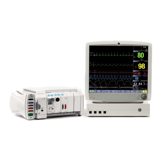
System introduction System introduction 3.1 Short description of the equipment The CARESCAPE Monitor B850 is a modular multi-parameter patient monitor that is meant for high-acuity applications. The monitor can be used with most patient populations within a professional healthcare facility, but acquisition modules may have limitations for use based on the patient’s age, weight, or clinical condition, or on the type of the care unit (for example, OR or ICU only). -
Page 18: Cpu Unit
CARESCAPE Monitor B850 3.2.1 CPU unit The primary function of the patient monitor is to render a clinically meaningful display of acquired patient data and allow the caregiver control (alarms, configuration, etc.) of the system through the user interface. The CPU unit is the central processing unit for the patient monitoring system and provides a link between parameter acquisition and input/output devices. -
Page 19: Input Devices
System introduction 3.2.3 Input devices You can connect several USB input devices to the patient monitor, including alphanumeric keyboard, mouse, remote control and barcode reader. Refer to the patient monitor’s supplemental information manual for a list of compatible USB input devices. Keyboard A washable, antibacterial keyboard is specified for use with the monitor. - Page 20 CARESCAPE Monitor B850 Barcode reader The barcode reader can be used to scan a Technician ID and Patient Information from barcodes when admitting patients. 2106778-001...
-
Page 21: Module Frames
System introduction 3.2.4 Module frames F5 and F7 E- module frames provide an interface between the patient monitor and E-Modules. The F5 Frame has five module slots that support all E-series acquisition modules. It supports both PDM and E-PSMP with a slide mount. The F7 Frame has seven module slots, but it does not have a slide mount for the PDM or E-PSMP. -
Page 22: Carescape Network Mc Or S/5 Network
The IX Network provides you access for example to the MUSE server for MUSE/12SL reports, to Citrix server for iPanel connections and to the IX printers. It also enables centralized Webmin access for service personnel from within the hospital and the InSite RSvP remote service connectivity to GE’s support center. 2106778-001... -
Page 23: Unity Network Id Connectivity Device
3.2.8 Unity Network ID connectivity device The Unity Network ID connectivity device acquires digital data from up to eight peripheral bedside devices (not necessarily manufactured by GE), processes this data and transmits the formatted data to the patient monitor. The supported interfaces include anesthesia machines, ventilators, gas analyzers, continuous cardiac output devices, pulse oximeters, transcutaneous monitors and point-of-care blood gas monitors. -
Page 24: Printers And Recorders
CARESCAPE Monitor B850 The display is a 19” touchscreen LCD with a Trim Knob control. The display provides both visual and audible alarms and connectivity to the USB input devices. Refer to the patient monitor’s supplemental information manual for a list of compatible displays. -
Page 25: Service Interface
Internet for secure communications between the customers’ and GE’s firewalls. InSite RSvP consists of Enterprise Server, which resides at GE’s support center, and Remote Service Agent that resides on a system at the customer site (or on a PC controlling the system(s) at the customer site). -
Page 26: Controls And Connectors
CARESCAPE Monitor B850 3.3 Controls and connectors 3.3.1 Front view Display Alarm light Power on/standby button Power indicators Trim Knob control Ambient light detector lens Audio alarm paused/off area (blue) Alarm light area (blue, yellow, or red) 2106778-001... -
Page 27: Rear Views
System introduction CPU unit Power indicator: Illuminates green when the power is turned on. Four M-ports: for connecting the remote control, PRN 50-M recorder, remote alarm box (remote nurse call), or a Unity Network Interface Device (ID) to the monitor. 3.3.2 Rear views Display Power on/off switch... -
Page 28: Iec 60601-1 Classifications
CARESCAPE Monitor B850 CPU unit Power on/off switch Power inlet connector Equipotential connector Four USB ports for connecting the touchscreen display, remote control, keyboard, mouse, and barcode reader Two Ethernet network connectors for connecting the MC and IX networks. The MC Network establishes communication and allows patient data to be sent to a CARESCAPE Central Station. -
Page 29: Service Information
• Any unauthorized attempt to repair equipment under warranty voids that warranty. • It is the user's responsibility to report the need for service to GE or to one of their authorized agents. • Failure on the part of the responsible individual, hospital, or institution using this equipment to implement a satisfactory maintenance schedule may cause undue equipment failure and possible health hazards. - Page 30 Device label Every GE device has a unique serial number for identification. The serial number is written in a device label. A sample of the information on a device label is shown below. The device plate is located on the outside of the patient monitor.
-
Page 31: Product Security
Malicious software protection Vigilant defense on many levels is required to keep systems free from compromise by malicious software. Effective protection requires cooperation and partnership between GE and our customers. Based on the Linux Operating System, the patient monitor has a built-in firewall to allow external communication to occur on a limited number of ports on the IX Network. -
Page 32: Security Operations
3.6.2 Security operations Network security GE requires that the MC port of the patient monitor be connected to a physically or virtually dedicated CARESCAPE Network MC or S/5 Network, isolated from all other networks. GE requires that the IX port of the patient monitor be connected to a physically or virtually dedicated CARESCAPE Network IX with controlled connection to the organization’s general... -
Page 33: Product Change Management
IX Network (reflexive). 3.6.3 Product change management GE has rigorous software verification and validation processes. Any software update needs will be communicated by GE. The patient monitoring system, including all aspects of software, should be used as it was intended by GE. - Page 34 CARESCAPE Monitor B850 The following symbols appear on one or more of the devices. Fuse. Replace with identical type and rating fuse. Do not reuse. Battery (monitor): The flashing orange symbol indicates that there is a battery failure/missing battery. Battery (monitor): The solid orange symbol indicates that the battery is being charged.
- Page 35 System introduction The following symbols appear on one or more of the devices. On/standby button. Standby or power indicator. USB connectors. Ethernet connectors. Serial interface. ePort connector for PDM module and E-module frame. DVI connector. Video output connector for digital or analog source.
- Page 36 CARESCAPE Monitor B850 The following symbols appear on one or more of the devices. Gas outlet. Zero all. (PDM) Degree of ingress protection. Degree of protection against harmful ingress of water: Components not marked with an IPXn code are rated as Ordinary (no protection against fluid ingress).
- Page 37 System introduction The following symbols appear on one or more of the devices. Defibrillator synchronization connectors. Stacking limit by number. Date of manufacture. This symbol indicates the date of manufacture of this device. The first four digits identify the year, the following two digits identify the month, and the last two digits identify the day.
- Page 38 CARESCAPE Monitor B850 The following symbols appear on one or more of the devices. Catalogue or orderable part number. Device serial number. Device model or type. Every device has a unique marking for identification. The UDI marking appears on the device label. Mass of typical portable RGM (respiratory gas monitor) configuration.
- Page 39 System introduction The following symbols appear on one or more of the devices. Temperature limitations. Humidity limitations. Keep dry. Protect from rain. Fragile. Handle with care. This way up. This symbol indicates that the waste of electrical and electronic equipment must not be disposed as unsorted municipal waste and must be collected separately.
- Page 40 CARESCAPE Monitor B850 The following symbols appear on one or more of the devices. Indicates that the product is certified for both the U.S. and Canadian markets. FCC. USA only. Complies with applicable US government (Federal Communications Commission) radio-frequency interference regulations.
- Page 41 System introduction The following symbols appear on one or more of the devices. In order to maintain the declared EFUP, the product shall be operated normally according to the instructions and environmental conditions as defined in the product manual, and periodic maintenance schedules specified in Product Maintenance Procedures shall be followed strictly.
- Page 42 CARESCAPE Monitor B850 The following symbols appear on one or more of the devices. Brazil only. Approved under ANATEL (Agência Nacional de Telecomunicações) requirements. South Africa only. Approved under ICASA (Independent Communications Authority of South Africa) requirements. Korea only. Approved under KCC (Korea Communications Commission) requirements.
-
Page 43: User Interface Symbols
System introduction 3.8 User interface symbols The following symbols appear in the software user interface Alarm off indicator. The symbol may not display at the central station or on a remote bedside monitor. Alarm priority indicator: High (red). Indicates a high priority alarm. Alarm priority indicator: Medium (yellow). - Page 44 CARESCAPE Monitor B850 The following symbols appear in the software user interface Locking setting indicator. Indicates this setting is locked and cannot be adjusted. Network connection indicator. Indicates the patient monitor is connected to the Local Area Network (LAN). Network connection indicator. Indicates the monitor is connected to the Wireless Local Area Network (WLAN).
- Page 45 System introduction The following symbols appear in the software user interface PDM battery gauge indicator. Indicates the charge level of the battery. PDM battery failure indicator. Indicates the battery is not available for use. Snapshot indicator. Indicates the event has an associated snapshot. Beat source indicator.
- Page 46 CARESCAPE Monitor B850 The following symbols appear in the software user interface signal strength indicator. Indicates the signal strength, with three asterisks indicating the strongest signal. NMT Stimulus beep volume icon. Adjust the volume of the tone that sounds when a stimulus pulse is generated. Progress bar.
-
Page 47: Using Webmin Service Interface
Using Webmin service interface Using Webmin service interface Webmin is a browser-based service interface that is used to configure the platform settings of the patient monitor and to diagnose and retrieve system information for maintenance and troubleshooting. Local access to Webmin You can access Webmin locally through the integrated browser on the patient monitor or from a configured service PC that is connected to the IX port of the patient monitor with an Ethernet crossover cable. -
Page 48: Local Access To Webmin With A Service Pc
CARESCAPE Monitor B850 Continue to 4.4. Login to Webmin. Closing Webmin Select to close Webmin and return to the main display. 4.2 Local access to Webmin with a service PC You can access Webmin locally by connecting an Ethernet crossover cable between the service PC and the IX connector of the patient monitor. -
Page 49: Remote Access To Webmin Using A Service Pc Over The Ix Network
Using Webmin service interface NOTE: For more information on how to configure the IP address, refer to the PC’s documentation. Launch a web browser on the service PC. In the Address field, type https://[IX IP address]:10000 and press Enter. NOTE: [IX IP address] is the IX Network IP address of the patient monitor. The Login to Webmin dialog box displays. - Page 50 CARESCAPE Monitor B850 IX Netmask: ______________________ Configure the service PC’s IP address and subnet mask to the same network segment with the patient monitor’s IX Network. NOTE: For more information on how to configure the IP address, refer to the PC’s documentation.
-
Page 51: Login To Webmin
Using Webmin service interface 4.4 Login to Webmin In the Login to Webmin dialog box, type the username and password and select Login or press Enter. Username: biomed Password: Change<space>Me NOTE: Username and password are case sensitive. NOTE: “Change Me” is the factory default password for the username “biomed”. Refer to section 7.14. -
Page 52: Webmin Configuration Modules
CARESCAPE Monitor B850 Figure 2 Webmin user interface when accessed using the service PC 4.5 Webmin configuration modules The Webmin service interface includes the following configuration modules. Select Help for additional information related to each Webmin module. 2106778-001... - Page 53 Using Webmin service interface Webmin module Use the module Admit Settings to configure Patient ID Prefix and barcode settings. Certificate Management to manage SSL certificates installed on the system. With this module, self-signed certificates and certificate signing requests (CSR) can be generated. Certificates can be imported, exported, deleted and viewed.
-
Page 54: Webmin Information Modules
CARESCAPE Monitor B850 Webmin module Use the module Restart to shutdown and restart the patient monitor automatically via Webmin. NOTE: The patient must be discharged in order to enable monitor restart via Webmin. Settings to transfer platform and/or clinical settings from one patient monitor to another, to take backup copies of the settings to an external device and to restore the settings from an external device. -
Page 55: Webmin Diagnostics Modules
Using Webmin service interface 4.7 Webmin diagnostics modules Access Webmin service interface to view hardware statistics, ping a network deviceand view or download log files. The Hardware Statistics module displays several internal voltages, temperatures and power consumption. Ping a TCP/IP network device- Use this Webmin feature to verify connectivity with a network device on the MC Network and IX Network. - Page 56 CARESCAPE Monitor B850 For your notes: 2106778-001...
-
Page 57: Pre-Installation Requirements
Confirm that all components are undamaged. If any of the components is damaged, contact the shipper. Confirm that all components are included. If any of the components is missing, contact your GE Healthcare distributor. WARNING EXCESSIVE LEAKAGE CURRENT - If the device has been transported or stored outside operating temperature range allow it to stabilize back to operating temperature range before removing it from the plastic bag. -
Page 58: Network Infrastructure
CARESCAPE Monitor B850 WARNING The use of accessories, transducers and cables other than those specified may result in increased emissions or decreased immunity performance of the equipment or system. WARNING For detailed instructions and information regarding supplies and accessories, always refer to their own instructions for use. 5.3 Network infrastructure Ensure that the applicable network infrastructure is in place prior to the installation of the patient monitor. -
Page 59: Installing The Mounting Hardware
Pre-installation requirements 5.4 Installing the mounting hardware Ensure that all the applicable/ required mounting hardware is properly installed prior to the installation of the patient monitor: • Mounting hardware for the patient monitor, either for a stand-alone installation or for an installation to an anesthesia machine or to a ventilator •... - Page 60 X-ray equipment or MRI devices are a possible source of interference as they may emit higher levels of electromagnetic radiation. Changes or modifications to this device/system not expressly approved by GE may cause EMC issues with this or other equipment. This device/system is...
-
Page 61: Hardware Installation
WARNING EXPLOSION OR FIRE -Using non-recommended batteries could result in injury/burns to the patients or users. Only use batteries recommended or manufactured by GE. WARNING EXPLOSION HAZARD - Do not incinerate a battery or store at high temperatures. Serious injury or death could result. -
Page 62: Installing The Battery Into The Pdm Module
CARESCAPE Monitor B850 One LED flashing: < 10% of full-charge capacity remaining. NOTE: Keep the PDM connected to the patient monitor and the patient monitor connected to the AC mains until the PDM battery is fully charged. 6.1.2 Installing the battery into the PDM module Open the battery door by gently pulling on the battery door pull tab. - Page 63 For details, refer to the installation instructions included with the flush mount. NOTE: The GE logo can be rotated for vertical mounting configurations. WARNING Never install equipment above the patient.
-
Page 64: Connecting Displays
CARESCAPE Monitor B850 CAUTION The device/system should not be used adjacent to, or stacked with, other equipment. Consult qualified personnel regarding device/system configuration. 6.3 Connecting displays 6.3.1 Connecting local displays WARNING To prevent liquids from entering the display casing, do not tilt the display more than +/-15 degrees. -
Page 65: Connecting Remote Displays
Hardware installation Display port 1 Display Touchscreen interface port DVI-I 1 Display 1 USB1 or RS-232 1 Display 1 cloned USB1 or RS-232 1 The secondary display The secondary display must be a digital display. It can be either an USB or serial touchscreen, or a non-touchscreen display. - Page 66 CARESCAPE Monitor B850 If complete isolation is not required, this method will provide the most cost effective means of extending your display installation. This type of installation should not be used for connections to non-medically used rooms according to IEC 60601-1. Displays may be extended up to 15 meters from the patient monitor using the following cables: •...
-
Page 67: Securing The Usb Cable Connections Of The Displays
Hardware installation 6.3.3 Securing the USB cable connections of the displays Secure the connected USB cables of all displays to the CPU unit. Use the existing retaining clips attached to the patient monitor. Secure the USB cables connections to the displays according to the instruction included in the display package. -
Page 68: Connecting A F5 Or F7 Frame To A B850 Patient Monitor
CARESCAPE Monitor B850 horizontal position. To avoid the risk of equipment malfunction, make sure the frames are not used in any other position. WARNING Do not use identical measurement modules or modules that map a measurement to the same channel or parameter window. If such modules have been connected, remove the module that has been most recently connected. -
Page 69: Installing A Psmp Module To An F5 Frame
Hardware installation 6.4.2 Installing a PSMP module to an F5 Frame Connect a PSMP module by aligning it with the insertion guides on the outside of the frame. Push the module into the frame until it stops. To remove the PSMP module, pull the pull tab out and slide the module out of the guides. 6.4.3 Installing a PSMP module to an F7 Frame WARNING PHYSICAL INJURY- Take care when mounting devices to an IV pole. -
Page 70: Connecting A Pdm Module To An F5 Frame
CARESCAPE Monitor B850 With the module properly oriented, align the module insertion guide slot with the insertion guide. Push the module into the frame until it clicks. To remove a parameter module, grasp it firmly, press the release lever on bottom of module, and pull out of the guides. - Page 71 Hardware installation WARNING PHYSICAL INJURY — Do not install the PDM above a patient. Make sure the battery is completely inserted and the battery door is completely closed. Falling batteries could seriously or fatally injure neonatal or other vulnerable patients. WARNING PHYSICAL INJURY —...
-
Page 72: Connecting To The Mains Power
CARESCAPE Monitor B850 6.5 Connecting to the mains power WARNING Use only AC power cords recommended or manufactured by GE. WARNING EXCESSIVE LEAKAGE CURRENT - To avoid summation of leakage currents when interfacing the device with other equipment, the devices may only be... -
Page 73: Connecting To The Mc Network Or The S/5 Network
This could lead to incorrect drug dose calculations, hemodynamic calculations, or oxygenation calculations. Prior to installing the System, please contact the GE Healthcare Aware Gateway HL7 Integration Engineering Team or your GE Healthcare service representative to verify or update your Aware Gateway configuration. -
Page 74: Connecting M-Port Devices
• Remote control • Barcode reader NOTE: Always use a GE-supplied barcode reader for the CARESCAPE monitors. Refer to the included installation instructions for more details. WARNING Use only washable keyboard with at least IPX1 protection against ingress of water. -
Page 75: Connecting A Local Printer To The Ix Connector
NOTE: Refer to the iCollect User's Manual for more information about the iCollect. NOTE: Contact GE Healthcare Service to get more information about interfacing other data acquisition systems to the patient monitor. 6.11 Connecting a local printer to the IX connector You can connect a local laser printer directly to the patient monitor’s IX connector with a... - Page 76 CARESCAPE Monitor B850 For your notes: 2106778-001...
-
Page 77: Configuration
Configuration Configuration The configuration of the patient monitor consists of platform configuration and clinical configuration. This chapter describes how to perform the platform configuration tasks needed to take the patient monitor into use for the first time and the configuration tasks needed for administration and maintenance thereafter. -
Page 78: Selecting And Configuring Carescape Network
CARESCAPE Monitor B850 Select Save. The hostname configuration will take effect immediately. 7.2.2 Selecting and configuring CARESCAPE Network To select CARESCAPE Network MC for the real-time network infrastructure: Log in to Webmin. Select Configuration > Network > Wired Interfaces. The current network configuration is shown in the Present Configuration table. Below Select Network Type in the Network Configuration window, select the applicable network type: CARESCAPE Network. -
Page 79: Selecting And Configuring S/5 Network
Configuration • CF:xx:xx:xx:xx:xx: Reserved by IANA for PPP • FF:FF:FF:FF:FF:FF: Broadcast • Multicast addresses in which the first octet is an odd number (for example, 97:xx:xx:xx:xx:xx) Select the applicable Speed & Duplex option. 10. Select Save. The default network speed is 10 Mbps half duplex, which suppresses the effects of network storms resulting from network misconfigurations. -
Page 80: Configuring Adt Server Settings
To prevent potential time synchronization issues, you should set the new device’s time to be as close as possible to the time (within one minute or less) used by the existing GE devices on the CARESCAPE Network. -
Page 81: Configuring Printers
Configuration NOTE: The same unit name must be set for all the patient monitors and CARESCAPE Central Stations (CSCS) that are connected to the same care unit in the MC Network. Bed name shall be unique to each patient monitor in the same care unit. NOTE: Unit and bed name selections are not available if network selection is S/5. -
Page 82: Deleting A Printer
Select Save. 7.6 Configuring Citrix Configure the Citrix connection for iPanel software. NOTE: GE is not responsible for installing or configuring the Citrix server. NOTE: Contact hospital's IT Administrator or biomedical department to obtain values to the following fields. NOTE: Server address, initial program and Citrix session timeout are mandatory fields. -
Page 83: Troubleshooting
Configuration Field name Description and valid choices Username Any valid Windows username. You can leave this field empty to allow anonymous login. The maximum length is 128 characters. Password Any valid Windows password. You can leave this field empty to allow anonymous login. The maximum length is 128 characters. -
Page 84: Configuring Muse/12Sl
CARESCAPE Monitor B850 Citrix Timeout: The number of minutes that a Citrix session will remain open after the Citrix Window is closed. Keeping the session alive allows users to quickly return to their last session but locks a Citrix license. Citrix Startup Time: Estimated time, in seconds for connecting Citrix. -
Page 85: Admit Settings
Configuration 7.8 Admit settings 7.8.1 Patient ID prefix The patient monitor will automatically generate a temporary, unique patient ID when a patient with unknown ID is admitted to the patient monitor. The patient monitor will use this temporary patient ID for all 12SL reports that are sent to MUSE until the patient is discharged from the patient monitor, or his/her patient ID is changed. -
Page 86: Configuring Length Delimited Parser Information
CARESCAPE Monitor B850 Select Save. If you selected No Parser, the barcode setting configuration is complete. For a Length or Character Delimited Parser, follow the applicable instructions. 7.8.3 Configuring length delimited parser information. 7.8.4 Configure character delimited parser information. - Page 87 Configuration Example of length delimited parser information In this example, the barcode contains 10 items. The following table lists the starting position and length of each item. Item Starting position Length First Name Last Name Day of Birth Month of Birth Year of Birth Age Unit Gender...
-
Page 88: Configure Character Delimited Parser Information
CARESCAPE Monitor B850 7.8.4 Configure character delimited parser information Points to note If you configure Age, you must either select the Age Unit item or one of the age units (e.g., Years, Months, Weeks, Days) below Fixed Option. If you configure Height, you must either select the Height Unit item or one of the height units (e.g., Feet, Inches, Meters, Centimeters, Millimeters) below Fixed Option. - Page 89 Configuration In the Position column of the Admit/Discharge Configuration window, enter the sequence number of each item included in the barcode. Use incremental numbers from 1 (the left-most field) up to 16 (the right-most field). If an item is not included in the barcode, leave the Position field blank for the item. Below Field Delimiter, in the Delimiter field, enter the special character that separates the fields on the barcode.
-
Page 90: Barcode Data Specifications
CARESCAPE Monitor B850 Item Sequence number of the item in the barcode Height Height Unit Weight The following sample shows the corresponding entries in the Admit/Discharge Configuration window. 7.8.5 Barcode data specifications Points to note The maximum length of the entire barcode is 300. 2106778-001... - Page 91 Configuration If the field value is longer than the maximum length indicated, the right-most characters will be truncated when the value is displayed in the Admit/Discharge menu. If a field contains a forbidden character, that character will be replaced with a space when it is displayed in the Admit/Discharge menu.
-
Page 92: Setting Power Frequency
CARESCAPE Monitor B850 7.9 Setting power frequency WARNING Incorrect power line frequency setting could adversely affect ECG and EEG processing. Log in to Webmin. Select Configuration > Power Frequency. In the Power Frequency window, select the applicable power line frequency. Select Save. -
Page 93: Module Asset Settings
Configuration Refer to the Module Frames and Modules Service Manual for detailed information on how to change these settings. Webmin Module Description sub-module Assets Settings This setting allows you to view the customer assigned asset number of the PDM. Licensing This setting allows you to manage the PDM feature licenses. -
Page 94: Password Management
See the user’s manual and supplemental information manual for more information. For information on passwords related to other user accounts, contact GE service. 7.14.2 Changing passwords You can change the passwords for the biomed and clinical users. WARNING Control of this user’s password is critical to ensure that Webmin on this device is accessed only by trained and authorized personnel. -
Page 95: Resetting The Password
Configuration 7.14.3 Resetting the password If the valid password for the biomed user account is forgotten, contact your local GE representative to request a password reset key. Provide the following information when requesting a password reset key: • serial number of the monitor When you have received the password reset key: Go to the service interface login screen. -
Page 96: Enabling Remote Service Agent/ Connection
Password is required. Otherwise, select None. Remote Service Configuration Item Description Comments System ID Identifies the system to the GE back office These values are read-only servers. and are unique. Serial Number Identifies the unit and is set at the time of manufacture. -
Page 97: Testing The Connectivity
Configuration 7.16.3 Testing the connectivity NOTE: Connectivity test works only if the connection is enabled, that is the current state is enabled/running. Log in to Webmin. Select Configuration > Remote Service. In the Sub-Modules for Remote Service menu, select Control. Below Test Connectivity in the Remote Service Control window, select Test to test the connectivity to the remote service server. -
Page 98: Loading Settings
CARESCAPE Monitor B850 Select Configuration > Settings. In the Sub-Modules for Settings menu, select Save. In the Save Settings window, select the radio button next to the type of settings you want to save. Select Save. According to your Webmin access: If you are using Webmin on a service PC, you can save the settings file to any mass storage device connected to the service PC: ... - Page 99 Configuration activation process with a delay during an active patient case, but the new settings will activate only after the next case reset / patient discharged. Log in to Webmin. Select Configuration > Settings. In the Sub-Modules for Settings menu, select Activate. In the Activate Settings window, select the settings that you want to activate: •...
-
Page 100: Canceling Pending Settings Activation
CARESCAPE Monitor B850 Select NOTE Immediately Activate the new settings The patient monitor must be in a Immediately. case reset / patient discharged state. After next case end / Take the new settings in use This option allows you to initiate the with a delay, after the next setting activation process with a discharge... -
Page 101: License Management
Alternatively, you can enable and activate individual software packages and host software feature licenses by entering the required activation code manually. NOTE: Contact GE Healthcare to acquire activation codes for licenses. 7.18.1 Enabling and activating host software package NOTE: As a factory default the ICU software package is always activated. -
Page 102: Uploading License File
By factory default, the monitor has a self-signed certificate of the Webmin web client issued by GE. To improve access security, you can install a certificate issued and signed by a trusted certificate authority to the monitor. The certificate authority must be recognized and trusted by the web browsers used to access the service interface. -
Page 103: Generating A Certificate Signing Request (Csr)
Configuration • Confirm Password: Re-enter the password for the private key/certificate. NOTE. You must enter the password each time that an SSL service that uses this key is started. If you do not want to provide the password for each service, leave the Password field blank. -
Page 104: Managing The Current Certificate Or Private Key
CARESCAPE Monitor B850 Select Configuration > Certificate management > Import Key or Signed Certificate. To upload the certificate file: In the Certificate file to upload field, select Choose file, search the drive and folder where the file is located, and select the file you wish to upload. Follow the instructions of the web browser. -
Page 105: Activating The Installed Software
Configuration • GE Healthcare Software Transfer Utility that runs on a service PC. With this application, you can transfer new software to the patient monitors over the CARESCAPE Network IX (IX Network) or a crossover cable. • InSite RSvP You can transfer the software in the background, without affecting normal patient monitoring. - Page 106 CARESCAPE Monitor B850 Select Next. The selected Software activation window appears. According to the software you are activating, proceed to: • Activating host software immediately • Activating host software after next case end / discharge • Activating module software • Activating EMBC or UIC software Activating host software immediately Before you start:...
- Page 107 Configuration In Erase Inactive Software After Activation, select: to keep the currently active software version as inactive software after the new software version is activated successfully. This option lets you restore the patient monitor to the previous software version later. to erase the currently active software version permanently after the new software version is activated successfully.
- Page 108 CARESCAPE Monitor B850 In the Host Software window, verify that the software that you activate is listed as Inactive in Current Software State. In Software License, if applicable, enter the Activation Code for the new software version. After next case end / discharge. In Software Activation, select In Erase Inactive Software After Activation, select: to keep the currently active software version as inactive software after...
- Page 109 Configuration The software activation starts automatically after the clinical user performs a patient discharge / case end the next time. The patient monitor shows a screen saver that informs about the ongoing software activation: Software activation in progress. Do not disconnect any measurement modules or other peripheral devices, or shut down the monitor until the software activation is complete.
-
Page 110: Canceling Pending Host Software Activation
CARESCAPE Monitor B850 • Make sure that all the target peripheral devices are connected to the patient monitor. NOTE: Do not disconnect any peripheral device, or shut down the patient monitor, until the software activation is successfully completed. To activate EMBC and UIC software: EMBC/UIC Software window, in Current Software State, verify that the software you want to activate is listed as Inactive. -
Page 111: Erasing An Inactive Software Version
Configuration The pending software activation is cancelled and the patient monitor continues running the current software version. 7.20.4 Erasing an inactive software version You can erase an inactive host software version from the patient monitor. Erasing can prevent the activation of a wrong software version by mistake. Log in to Webmin. - Page 112 CARESCAPE Monitor B850 For your notes: 2106778-001...
-
Page 113: Installation Checkout
Installation checkout Installation checkout The purpose of the installation checkout procedure is to ensure that the system is properly installed and configured for use. The installation check covers the CARESCAPE B850 monitoring system including the following devices: • CARESCAPE B850 host •... -
Page 114: Electrical Safety Tests
NOTE: Before proceeding, make sure that all test equipment is properly calibrated, maintained and functioning. NOTE: GE recommends that the qualified personnel performing the tests should record the test results of each electrical safety test, for example by using the installation / maintenance check forms included in this manual. -
Page 115: Ground Integrity Check
Installation checkout 8.2.4 Ground integrity check Listed below are two alternative methods for checking the ground integrity: “a) Ground continuity test” “b) Impedance of protective ground connection”. These tests determine whether the device's exposed metal and power inlet's ground connection has a power ground fault condition. -
Page 116: Ground Leakage Current Test
CARESCAPE Monitor B850 When taking this measurement, flex the unit’s power cord along its length. There should be no fluctuations in resistance. Acceptance criteria: • For equipment without a power supply cord, the impedance between the protective ground terminal and any accessible metal part which is protectively grounded shall not exceed 0.1 Ohms. -
Page 117: Testing Touch Current
Installation checkout Read and record the current leakage indicated on the safety tester. Configure the safety analyzer as follows (SFC): Polarity: REVERSED Neutral: OPEN Read and record the current leakage indicated on the safety tester. Configure the safety analyzer as follows (NC): ... - Page 118 CARESCAPE Monitor B850 NOTE: *The measuring device (MD) represents the network and voltage measuring instrument and its frequency characters according to IEC 60601-1. Configure the safety analyzer as follows (NC): Polarity: NORMAL Neutral: CLOSED Earth (GND): CLOSED Power on the device under test.
-
Page 119: Patient Leakage Current Tests - Overview
Installation checkout Read and record the current leakage indicated on the safety tester. 10. Configure the safety analyzer as follows (SFC): Polarity: REVERSED Neutral: OPEN Earth (GND): CLOSED 11. Read and record the current leakage indicated on the safety tester. 12. -
Page 120: Patient (Source) Leakage Current Tests
CARESCAPE Monitor B850 Patient connector Module E-COP, E-COPSv P4/P8 E-PiCCO E-NSATX, E-NSAT SpO2 E-Masimo SpO2 E-NMT E-BIS 1. Connect the BISx Digital Signal Processing Unit with the Patient Interface Cable (PIC+) to the E-BIS module. 2. Connect the specified test body to the PIC+ cable. NOTE: The patient isolation is in the BISx Digital Signal Processing Unit, not in the E-BIS module. - Page 121 Installation checkout NOTE: Perform this test for all the connected parameter modules and patient connectors specified in Table Configure the safety analyzer as follows (NC): Polarity: NORMAL Neutral: CLOSED Earth (GND): CLOSED Power on the device under test. Read and record the current leakage indicated on the safety tester.
-
Page 122: Patient (Sink) Leakage Current Tests
CARESCAPE Monitor B850 8.2.9 Patient (sink) leakage current tests This procedure measures the leakage current from an applied part connector of the device to ground. Perform the test in Normal Condition (NC) with normal and reverse polarity. NOTE: Refer to the instructions delivered with the safety analyzer to perform this test. NOTE: *The measuring device (MD) represents the network and voltage measuring instrument and its frequency characters according to IEC 60601-1. -
Page 123: Test Completion
Installation checkout Repeat this test for all the connected parameter modules and patient connectors specified in Table Acceptance criteria: All readings shall be less than or equal to 50 A. • 8.2.10 Test completion Disconnect the safety analyzer from the power outlet. Disconnect the test equipment from the patient monitor. -
Page 124: Configuration Information
CARESCAPE Monitor B850 Select Information > Device Information. Verify that the device information is correct: The connected parameter modules are identified. The connected CARESCAPE Network ID interfaces are identified. The connected USB input devices are identified. Stay connected to Webmin. 8.3.4 Configuration Information Select Information >... -
Page 125: Alphanumeric Keyboard
Installation checkout 8.3.7 Alphanumeric keyboard Perform this test only if an alphanumeric keyboard is connected to the patient monitor. Select Data & Pages > Admit/Discharge (or Start / End Case). Select the Patient tab > Edit Name & MRN. Enter Press to highlight the Medical Record Number field. -
Page 126: Printers
CARESCAPE Monitor B850 Check that a network symbol is displayed in the upper right corner of the screen. Select Data & Pages – Other Patients and select a patient from the list. Select View and verify that a window with parameters from another patient displays on the left side of the screen. -
Page 127: Test Completion
Installation checkout 8.3.13 Test completion Discharge Patient or Reset Case to discard any changes made to the patient monitor configuration during checkout. • Complete the Appendix A. Installation check form. 2106778-001... - Page 128 CARESCAPE Monitor B850 For your notes: 2106778-001...
-
Page 129: Theory Of Operation
Theory of operation Theory of operation 9.1 System block diagram 2106778-001... -
Page 130: Main Components
CARESCAPE Monitor B850 The system block diagram describes the functional units of the CARESCAPE Monitor B850. The following sections describe the operation and interaction of the different subsystems. 9.2 Main components The CPU unit is housed in a single package. The main components of the CPU unit are: •... -
Page 131: Speaker Assembly
Theory of operation • It has a non-volatile flash memory for the BIOS a volatile SDRAM memory for run time code execution and temporary data storage. • A detachable, non-volatile flash memory, USB Disk On Module (uDOM), is used as the permanent memory for application and service software, and to store clinical and platform settings. -
Page 132: External Interfaces
CARESCAPE Monitor B850 9.2.6 External interfaces M-Ports Four M-Ports are provided on the front of the CPU unit for connecting the PRN50 and Unity ID. Basic insulation (250 VAC) is provided to isolate the CPU unit from M-Port devices. Each M-Port supports the 1-Wire, Serial (RS-232) and Ethernet Protocols. -
Page 133: Maintenance And Checkout
Maintenance and checkout 10 Maintenance and checkout This chapter specifies the checkout procedure and the maintenance activities to be performed to the patient monitor after corrective maintenance and during planned maintenance. WARNING Only perform maintenance procedures specifically described in the manual. WARNING Planned maintenance should be carried out at recommended interval. -
Page 134: Visual Inspection
CARESCAPE Monitor B850 Planned maintenance schedule Perform the planned maintenance procedure every 2 years after installation. Perform the procedure in the following order: Visual inspection (section 10.1) Electrical safety tests (section 10.2) Functional check (section 10.3, all steps) Replace the CPU timekeeper battery every 5 years, or whenever the Service Monitor Error Code 0xHOST1100 message is shown. -
Page 135: Keypad And Remote
Maintenance and checkout Select Information > Device Information. Verify that the information about the connected module appears in the table named as “Acquisition Information – E-Modules”. NOTE: For some parameter modules, the table does not show the actual module information, but the information of the individual subassemblies inside the module. -
Page 136: 13Test Completion
CARESCAPE Monitor B850 Verify that the recorder starts printing. Let the recorder print for approximately 10 seconds and verify the following things from the printout: The header line contains the date, time and some other applicable status and configuration information. ... -
Page 137: Troubleshooting
Troubleshooting 11 Troubleshooting The problems and solutions in this section represent only a few of the faults that you may encounter and are not intended to cover every possible problem that may occur. This chapter focuses on troubleshooting technical problems. See the patient monitor’s user’s manual for troubleshooting monitoring problems and clinical configuration issues. -
Page 138: Configuration Information
CARESCAPE Monitor B850 11.2.1 Configuration information The Configuration Information module shows the current platform configuration of the patient monitor and the connected peripheral devices. To view configuration information: Log in to the Webmin. Select the Information tab. Select Configuration Information. Scroll down the page to view the configuration information: Configuration information •... -
Page 139: Device Information
Troubleshooting Configuration information Unit and Bed Name • Unit name and Bed name for CARESCAPE Network. Acquisition Information • STP/TP/ST configuration information and P/PT/PP configuration information from E- modules. E-module S/5 Printers • Printer name. IX Printers • Printer name, hostname or IP address. Printer Location •... - Page 140 CARESCAPE Monitor B850 Scroll down the page to view the device information: Device information • Host Information Active software version, Inactive software version, Host serial number, Host asset number, MC Network IP address, IX Network IP address, MC Network MAC address, IX Network MAC address, S/5 Network virtual ID, CPU hardware version.
-
Page 141: Webmin - Diagnostics Tab
Troubleshooting 11.3 Webmin - Diagnostics tab Access Webmin service interface to view hardware statistics, ping a network device and view or download log files. 11.3.1 Hardware statistics The Hardware Statistics module displays several internal voltages and temperatures. A value is displayed in red, if the current reading exceeds a pre-determined lower or upper limit, A value is displayed either as “0”... -
Page 142: Ping A Tcp/Ip Network Device
CARESCAPE Monitor B850 Measurement Description battery (in mV) Lithium Battery Voltage for the Real Time Clock Ambient temperature (in C) Ambient temperature of the CPU unit measured by the sensor in the main processor board CPU temperature (in C) An internal temperature of the CPU unit measured by the sensor in the main processor 945 temperature (in C) An internal temperature of the CPU unit measured by... - Page 143 Troubleshooting Log file name Contents • Webmin Action log Webmin user authentication and access related information (e.g., who accessed Webmin and when). • Webmin module settings changes (e.g., what was changed and when). • Software transfer history information, including the type and version of the transferred software, the origin and destination, and the date and time the software transfer occurred.
- Page 144 Select Download to save the log file to the USB flash drive. NOTE: Do not disconnect the USB storage device until downloading is complete. Send this log file to GE Service for further investigation. Downloading sGAS log files NOTE: To download sGAS logs, ensure that the module is connected to the monitor and the patient is discharged.
-
Page 145: Error Messages And Codes
NOTE: Do not disconnect the USB storage device until downloading is completed. Send the log file to GE Service for further investigation. NOTE: The module is reset after you have downloaded the sGAS log. The reset takes up to 1 minute, as it calibrates the gas sensor and zeroes the measurement. - Page 146 CARESCAPE Monitor B850 Message Possible causes Possible solutions Identical unit & bed A patient monitor with the Disconnect the patient monitor that name noticed identical unit and bed name is has the identical unit and bed name. on the network. Change the unit and bed name of the duplicate patient monitor unit and bed name.
- Page 147 Troubleshooting Message Possible causes Possible solutions Service Monitor The CPU timekeeper battery is Readjust the time and date first. Then Error Code empty. Time and date may be replace the CPU battery. 0xHOST1100 reset to factory settings. External alarm 1. The USB cable between the 1.
-
Page 148: Problems And Solutions
CARESCAPE Monitor B850 Message Possible causes Possible solutions Speaker failure 1. Speaker cable loose. 1. Connect the speaker cable. 2. Speaker failure. 3. Replace the speaker. 4. Processor board tone 5. Replace the processor board. generator or audio amplifier failure. 11.5 Problems and solutions Start-up failures 11.5.1... -
Page 149: User Interface Issues
CPU board. 2. uDOM software is The patient monitor 2) Replace uDOM. Contact GE service for support. corrupted. starts, but the start-up 3) Ensure that the attached uDOM has correct and 3. uDOM has sequence does not compatible software. - Page 150 CARESCAPE Monitor B850 Problem Possible cause Recommended actions • The quality of the display is not 1. Check the connection between the The cable is not connected good. video display and the patient monitor. properly. If necessary, replace the video display •...
- Page 151 Troubleshooting Trim Knob and alarm light issues Problem Possible cause Recommended action Trim Knob (only) is inoperative. Trim Knob cable loose. Connect Trim Knob encoder cable to the user interface board. Trim Knob encoder faulty. Replace the Trim Knob encoder. Alarm light does not illuminate Alarm light board is faulty.
- Page 152 CARESCAPE Monitor B850 Speaker / audible alarm issues Problem Possible cause Recommended action Audible alarms are not Audible alarms are turned off Enable audible alarms. sounding. (See Alarms Setup > Audible & Visual.) Alarm volume is low. Adjust alarm volume using Monitor Setup >...
-
Page 153: Incorrect System Time
(within one minute or less) used by the existing GE devices on the CARESCAPE Network. System time is incorrect when iCentral time incorrect. -
Page 154: Acquisition Module Problems
CARESCAPE Monitor B850 Unable to view a certain feature The software package in use 1. Log in to Webmin > Configuration > although the license is enabled. does not include the feature in Licenses >Software Package. question. (For example, 2. Select the correct option and select Anesthetic agent measurement Activate. -
Page 155: Carescape Network Communication Issues
Troubleshooting E-module issues Possible cause Recommended action Incompatible module Refer to the patient monitor’s supplemental information manual document to see the list of compatible modules. Faulty E-Module Frame Replace E-Module Frame or repair it with existing service parts. PDM module issues Possible cause Recommended action The external ePort cable is loose... - Page 156 CARESCAPE Monitor B850 2106778-001...
- Page 157 Troubleshooting Problem: No waveforms or parameters are displayed at the CARESCAPE Cental Station 2106778-001...
-
Page 158: S/5 Network Communication Issues
CARESCAPE Monitor B850 11.5.7 S/5 Network communication issues Check the following things before proceeding with any detailed network troubleshooting: • Check status of the network connection indicators, for reference see 3.8. • Check network compatibility. Refer to the patient monitor’s supplemental information manual. - Page 159 Troubleshooting S/5 Network Problem Possible cause Recommended action • Proceed to the iCentral Bedside monitor doesn’t The problem is related to the troubleshooting. register to the Monitor Network iCentral, or to the cabling • - all bedside monitors affected. between the iCentral and the Check the cabling between hub/switch.
- Page 160 CARESCAPE Monitor B850 For your notes: 2106778-001...
-
Page 161: Disassembly And Reassembly
Disassembly and reassembly 12 Disassembly and reassembly 12.1 Disassembly guidelines Field repair of the patient monitor is limited to replacing field replaceable units (FRUs). See chapter 13. Service parts for a detailed list of available FRUs. Attempting a field repair on a printed circuit board, or a factory sealed component or assembly could jeopardize the safe and effective operation of the monitor. -
Page 162: Required Tools
CARESCAPE Monitor B850 • GE recommends using the new fasteners (screws, washers, etc.) in the FRU kits rather than reusing the old fasteners. Some fasteners are not intended to be re-used more than three times. • Use only new screws when attaching parts into light metal parts. Before fastening a screw, turn it counterclockwise until it drops into an existing thread pattern. - Page 163 Disassembly and reassembly Disconnect all external cables connected to the CPU unit. Disconnect the power cord first from the wall outlet and then from the CPU unit. Detach the CPU unit from the mount if installed. Disassembly workflow Use this workflow diagram to identify the simplest way to replace the FRU parts of the CPU C1. Numbers in the diagram refer to the related step by step instructions in the Disassembly chapter.
-
Page 164: Unit Disassembly
CARESCAPE Monitor B850 12.2 Unit disassembly 12.2.1 Opening the enclosure cover When the CPU unit is opened, the electrical safety tests must always be performed after the monitor is reassembled. For more information, refer to the Corrective maintenance requirements in the 10. -
Page 165: Detaching The Udom
Replacing the uDOM Contact GE Service if you doubt that the uDOM is defective and needs to be replaced. Only GE Service can configure the new uDOM. - Page 166 CARESCAPE Monitor B850 Remove 2 screws on front of bezel. Torque [1.1 Nm]. Release 3 snap fingers to free bezel from the front of chassis. Remove the bezel. Reassemble the CPU C1 unit in the reverse order of disassembly. 2106778-001...
-
Page 167: Replacing The Third Video Card
Disassembly and reassembly 12.2.5 Replacing the third video card Disassemble first the following: Opening the enclosure cover. Remove the 2 jack screws holding the DVI-I connector to the rear panel. Torque [0.6 Nm]. Remove 4 screws holding the video board. Torque [1.1 Nm]. Lift the video card to disconnect the video card connector from the processor board. -
Page 168: Removing The Rear Panel
CARESCAPE Monitor B850 12.2.6 Removing the rear panel Disassemble first the following: Opening the enclosure cover. Remove 7 screws on the rear panel. Torque [1.1 Nm]. If the 3rd video card is installed, remove the 2 jack screws holding the DVI-I connector to the rear panel. -
Page 169: Replacing The Processor Board
Disassembly and reassembly 12.2.7 Replacing the processor board Disassemble first the following: Opening the enclosure cover. Removing the rear panel. If the 3rd video card is installed: • Remove the card according to Replacing the third video card. • Remove the 4 video card standoffs. Disconnect the speaker cable connection, light pipe (pull gently from the receptacle on the PCB), and power supply cable: 2106778-001... - Page 170 CARESCAPE Monitor B850 Remove the 8 screws that hold the processor board to the chassis. Remove the processor board. Torque [1.1 Nm]. Remove the screw that holds the uDOM to the old processor board. Remove the uDOM from the old processor board and reassemble it to the new processor board. Torque [0.3 Nm].
-
Page 171: Replacing The Power Supply
Disassembly and reassembly • FRU, CPU C1 Processor PCB Reassemble the CPU C1 unit in the reverse order of disassembly. 12.2.8 Replacing the power supply Disassemble first the following: Opening the enclosure cover. Removing the rear panel. Disconnect the power supply cable from the CPU board. Remove the 4 screws that hold the power supply to the chassis. -
Page 172: Replacing The Speaker
CARESCAPE Monitor B850 • FRU, CPU C1 Power supply Reassemble the CPU C1 unit in the reverse order of disassembly. 12.2.9 Replacing the speaker Disassemble first the following: Opening the enclosure cover. Removing the rear panel. Remove the power supply according to Replacing the power supply Disconnect the speaker cable from the CPU board. - Page 173 Disassembly and reassembly Remove the 2 screws and washers, that hold the speaker to the front bezel. Remove the speaker. Torque [1.1 Nm]. Replace the speaker. • FRU, Speaker assembly Reassemble the CPU C1 unit in the reverse order of disassembly. 2106778-001...
-
Page 174: Replacing The Rear Panel Labels
CARESCAPE Monitor B850 12.2.10 Replacing the rear panel labels Remove the old labels and attach the new labels. NOTE: Take care not to obstruct connector or screw openings when you fix the labels. 2106778-001... -
Page 175: Service Parts
10. Maintenance and checkout after you have replaced any service parts. 13.1 Ordering parts To order parts, contact GE Healthcare. Contact information is available at www.gehealthcare.com. Make sure you have all necessary information at hand. 13.2 List of FRUs FRU/Item part... - Page 176 CARESCAPE Monitor B850 FRU/Item part FRU/Item description FRU content number 2021440-013 FRU, CARESCPE CPU C1 3rd Video Card Includes 3rd video card assembly, 4 mounting screws, 4 standoff screws and 2 jackscrews. 2021440-009 FRU, M-Port keypad kit Includes all M-port Keypad assembly with all language labels.
-
Page 177: Exploded View
Service parts 13.3 Exploded view 2106778-001... - Page 178 CARESCAPE Monitor B850 For your notes: 2106778-001...
-
Page 179: Appendix A: Installation Check Form
Installation check form APPENDIX A: Installation check form CARESCAPE Monitor B850 Customer Monitor type Service record # Software version Service engineer Other devices connected to the monitor system Device Serial number Device Serial number Prior to testing verify all equipment is calibrated via “Cal” labeling and record Cal Due Dates Measuring equipment / test gases used: Equipment / tool / gas: Manufacturer:... - Page 180 CARESCAPE Monitor B850 Yes: Yes: you do not have to perform the electrical safety tests. To continue the installation check, mark the electrical safety test completion N.A. and proceed to Functional check. If available, attach the original electrical safety test results to this check form. No: continue to perform the electrical safety tests.
- Page 181 Installation check form Module type Observed result Acceptance PASS N.A. FAIL criteria 50 µA Single Fault Condition (SFC) Ground closed (normal) 50 µA Ground open (normal) 50 µA Ground closed (reverse) 50 µA Ground open (reverse) 10 µA Normal Condition (NC) Polarity: Reverse...
- Page 182 CARESCAPE Monitor B850 Notes Used service parts Signature Date A - 4 (4) 2106778-001...
-
Page 183: Appendix B: Maintenance Check Form
Maintenance check form APPENDIX B: Maintenance check form CARESCAPE Monitor B850 Customer Monitor type B850- Service record # Software version Service engineer Module type Start date Planned maintenance Corrective maintenance Prior to testing verify all equipment is calibrated via “Cal” labeling and record Cal Due Dates Measuring equipment / test gases used: Equipment / tool / gas: Manufacturer:... - Page 184 CARESCAPE Monitor B850 1 mA Single Fault Condition (SFC) Polarity: Normal 1 mA Polarity: Reversed Normal Condition (NC) Polarity: Reversed 500 µA EN /IEC 300 µA Testing touch current 100 µA Normal Condition (NC) Polarity: Normal EN /IEC Single Fault Condition (SFC) Ground closed...
- Page 185 Maintenance check form Functional check Observed result Acceptance criteria PASS N.A. FAIL InSite RSvP The patient monitor is active on InSite RSvP back office. Recorder The header line contains the correct information. The grid is clear. The waveforms labels appear in the printout as configured.
- Page 186 CARESCAPE Monitor B850 For your notes: B - 4 (4) 2106778-001...
-
Page 187: Appendix C: Display D19Kt Ver01
Display D19KT VER01 APPENDIX C: Display D19KT VER01 C.1 Disassembly and reassembly procedures Before you start, read the following general guidelines and make sure to follow them: 12.1. Disassembly guidelines 12.1.1. ESD precautions 12.1.2. Reassembly precautions 12.1.4. Before disassembly Detaching the Trim Knob, OSD Knob and/or Alarm Light Cover WARNING PATIENT MONITORING INTERRUPTION —... - Page 188 Use a flat blade screwdriver to remove the main Use a screwdriver to disassemble the alarm light cover. NOTE: Reassemble in reverse order. NOTE: Contact GE Healthcare if the display is faulty in any other way. C - 2 (4) 2106778-001...
- Page 189 Display D19KT VER01 C.2 Service parts Ordering parts To order parts, contact GE Healthcare. Contact information is available at www.gehealthcare.com. Make sure you have all necessary information at hand. List of FRUs FRU/Item part number FRU/Item description 2091940-001 Trim/OSD Knobs & Alarm Light Cover, D19KT...
- Page 190 CARESCAPE Monitor B850 For your notes: C - 4 (4) 2106778-001...
- Page 192 GE Healthcare Finland Oy Kuortaneenkatu 2 FI-00510 Helsinki FINLAND Tel: +358 10 39411 www.gehealthcare.com www.gehealthcare.com...