
Related Manuals for ABB 600T Series


Summary of Contents for ABB 600T Series
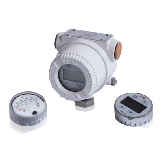
- Page 1 Operating instruction 600T EN Series IM/695FI_8 Model 695FI Field Indicator ASEA BROWN BOVERI - 1 -...
- Page 2 St Neots, U.K. – Cert. No. Q5907 liquid analysis and environmental applications. Stonehouse, U.K. – Cert. No. FM 21106 As a part of ABB, a world leader in process automation technology, we offer customers application expertise, service and support worldwide. UNI EN 29001 (ISO 9001) We are committed to teamwork, high quality manufacturing, advanced technology and unrivalled service and support.
-
Page 3: Table Of Contents
TRANSPORT CONTENTS After final calibration the instrument is packed in a carton Section Page (Type 2 of ANSI/ASME N 45.2.2-1978) intended to provide protection from physical damage. GENERAL DESCRIPTION ..3 TRANSPORT, STORAGE, HANDLING AND PRODUCT IDENTIFICATION ......... 3 HANDLING INSTALLATION ............... -
Page 4: Installation
ELECTRICAL CONNECTIONS INSTALLATION The Field Indicator unit may be mounted to a 50 mm (2 inch) WARNING - For installation in Hazardous Areas, i.e. pipe by means of its mounting bracket. The unit can be areas with dangerous concentrations of e.g. gases or rotated in the most appropriate viewing angle and locked dusts that may explode if ignited, the installation must in position. - Page 5 . . . ELECTRICAL CONNECTIONS 695FI as indicator only 600T transmitter terminal block REMOTE METER To receiver/ power supply Fig. 3 600T transmitter terminal block 695FI as junction box REMOTE METER To receiver/ power supply Fig. 4 If the terminal block of the transmitter is the latest version with three terminals, the connection is to be realized as explai- ned in pictures 3a and 4a.
-
Page 6: Calibration Procedure
CALIBRATION PROCEDURE The field indicator housing may be grounded using the ANALOG OUTPUT METER CALIBRATION external earth connection. The analog output meter provides a 90° scale indication. When the wiring connections are complete plug the meter It has either a 0 to 100 linear scale or a 0 to 10 square root and check that the cover O-ring gasket is properly in place, scale or special on request. - Page 7 CALIBRATION PROCEDURE . . . COMETER AND PROMETER CALIBRATION AND USE The name CoMeter is an acronym for COMMUNICATING the third line is used for seven alphanumeric characters to METER. ProMeter stands for PROGRAMMABLE METER. display units or messages. They can be connected, plug & play, into the terminal block In addition to the display the plastic membrane has 4 push of the 695FI field indicator.
- Page 8 CALIBRATION PROCEDURE . . . COMETER only COMETER and PROMETER ConF METER ENTER NEXT ConF ConF NEXT PREV NEXT PREV PREV MANUAL AUT O ENTER ENTER NEXT NEXT NEXT NEXT NEXT 20000 4000 . . . * PREV PREV PREV PREV PREV FULL SC...
- Page 9 CALIBRATION PROCEDURE . . . Under ConF PERCENT option, the user can decide for linear Then the CONF option appears. Using PREV or NEXT key, the user can select CONF, TRIM, or SQR output. When SQR output is selected, the output is linear from 0 to 20% (to 4% of input).
- Page 10 . . . CALIBRATION PROCEDURE TRIM ENTER LOOP IN_MAN. ENTER NEXT NEXT PREV NEXT PREV PREV LOOPTST RERANG. ENTER ENTER NEXT NEXT NEXT 0.000 40.000 PREV PREV PREV OTHER SET 4 mA 20 mA SET 20 mA 4 mA ENTER ENTER ENTER ENTER...
- Page 11 CALIBRATION PROCEDURE . . . REVIEW ENTER NEXT NEXT PREV PREV T AG 8 XMTR N' SENS N' UP/DOWN UNITS ENTER ENTER ENTER ENTER ENTER 1234567 KP A ABCDEFG 1234567 NEXT PREV NEXT PREV NEXT PREV (SCROLL) (SCROLL) (SCROLL) NEXT 1.0000 PREV 40.000...
-
Page 12: Disassembly And Reassembly
DISASSEMBLY AND REASSEMBLY FUNCTIONAL SPECIFICATIONS Input range: 4 to 20 mA nominal To remove the internal meter proceed as follows: 1) Remove the field indicator cover 2) Unplug the meter (see fig. 12) Operating range: 3.6 to 22 mA (for CoMeter ensuring HART functionality) 3) Replace it immediately by plugging another meter or install the proper link between the meter connections. -
Page 13: Addendum For "Ex Safety" Aspects And "Ip" Protection (Europe)
ADDENDUM FOR "EX SAFETY" ASPECTS AND "IP" PROTECTION (EUROPE) According to ATEX Directive (European Directive 94/9/EC of 23 March 1994) and relative European Standards which can assure compliance with Essential Safety Requirements, i.e., EN 60079-0 (General requirements) EN 60079-1 (Flameproof enclosures "d") EN 60079-11 (Intrinsic safety “i”) EN 60079-26 (Equipments, group II, category 1G), the field indicator of the 600T EN SERIES model 695FI have been certified for the following group, categories, media of dangerous atmosphere, temperature classes, types of protection. - Page 14 ADDENDUM FOR "EX SAFETY" ASPECTS AND "IP" PROTECTION (EUROPE) b) Certificate ATEX II 2 G Ex d IIC T6 (-40°C ≤ Ta ≤+70°C) ATEX II 2 G Ex d IIC T5 (-40°C ≤ Ta ≤+85°C) ATEX II 2 D Ex d tD A21 IP67 T80°C (-40°C ≤ Ta ≤+70°C) ATEX II 2 D Ex d tD A21 IP67 T95°C (-40°C ≤...
- Page 15 PRODUCTS & CUSTOMER SUPPORT A Comprehensive Instrumentation Range Customer Support Analytical Instrumentation ABB provides a comprehensive after sales service via a Worldwide Service Organization. Contact one of the following • Transmitters offices for details on your nearest Service and Repair Centre.
- Page 16 The Company's policy is one of continuous product improvement and the right is reserved to modify the specifications contained herein without notice. Printed in Italy (03.2012) ABB 2012 ABB Automation Products GmbH ABB Ltd ABB SpA ABB Inc. Schillerstrasse 72 Howard Road, St. Neots Measurement Products 125 E.