
Related Manuals for ABB 6553 Series


Summary of Contents for ABB 6553 Series
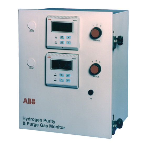
- Page 1 Model 6553 Series Instruction Manual Gas Analyzer Systems for Intrinsically Safe Hydrogen & 4689 502/502 Digital Displays Purge Gas Purity Measurement...
- Page 2 St Neots, U.K. – Cert. No. Q5907 environmental applications. Stonehouse, U.K. – Cert. No. FM 21106 As a part of ABB, a world leader in process automation technology, we offer customers application expertise, service and support worldwide. EN 29001 (ISO 9001) We are committed to teamwork, high quality manufacturing, advanced technology and unrivalled service and support.
-
Page 3: Table Of Contents
CONTENTS 1 INTRODUCTION ............2 9 OPERATION .............. 22 2 DESCRIPTION ............. 3 Normal ............22 Model 6553 Purge Gas Monitor ....3 9.1.1 Purging of Hydrogen 2.1.1 Range Display ........3 Coolant Gas ........22 Model 6548 000 9.1.2 Filling with Hydrogen Katharometer Analyser Panel ....... -
Page 4: Introduction
1 INTRODUCTION 1) The Model 6553 Gas Monitor Unit which is available in Warning. This operating manual applies only to several options. The inputs to these units are certified to those systems which have been designed and code Ex (ia) IIC under BASEEFA certificate Ex 77124/B/S constructed to the standards specified in the schedules of with the unit installed in the safe area only. -
Page 5: Description
2 DESCRIPTION 2 DESCRIPTION… 2 DESCRIPTION… All the various system options consist of one or more of the The Model 4689 displays are dedicated variants of the following units with the further option of fitting the monitor and Company's Model 4600 Series Indicator/Controllers. With this power supply units in a cubicle. -
Page 6: Model 6548 000 Katharometer Analyser Panel
…2 DESCRIPTION 2.2 Model 6548 000 2.3 Model 4234 Power Supply Unit – Fig. 3.3 Katharometer Analyser Panel – Fig. 2.2 Warning. Do NOT connect mains supply to the Each panel comprises a metering valve, a drying chamber, a power supply unit with the output terminals on open thermally lagged katharometer type 6548 001 and a flowmeter. -
Page 7: Preparation
(fixed to the 6553 system as shown in Section 3.1.5. the katharometer case) are also shown in Fig. 3.2. Intrinsic Safety Label (UK) ABB Kent-Taylor Ltd ABB Kent-Taylor Limited Katharometer Type 6548001 PURGE GAS MONITOR TYPE 6553 Ex (ia) IIC/BAS No.Ex77124/B/S... -
Page 8: Model 4234 Power Supply Unit
…3 PREPARATION 3.1.3 Model 4234 Power Supply Unit – Fig. 3.3 The identification and certification labels are fixed to the outside of the unit case, as shown. ABB Kent-Taylor Limited POWER SUPPLY UNIT TYPE 004234000 Intrinsic Issue 5 Safety Label Ex (ia) IIC/BAS.NoEx76180/B/S... -
Page 9: Coding System
3 PREPARATION 3.1.4 Coding System 6553/ Features of Upper Indicator Scale of Upper Indicator Features of Lower Indicator Scale of Lower Indicator Range selector Switch Not used Fitted with Labels Cubicle Type Special Features Mains Supply The equipment conforms with the requirements of SFA 3012 for class IIC gases to Code Ex (ia) IIC provided that the equipment is installed in accordance with instructions provided. -
Page 10: Mechanical Installation
4 MECHANICAL INSTALLATION… 4.1 Locating and Mounting System Items 4.1.1 Model 6553 Gas Monitor – Fig. 4.1 The monitor must be located in the safe area of the application plant in a sheltered interior environment. The monitor is intended to be panel mounted in a position to suit reading of the displays and with access to the rear to enable wiring interconnections to be made. -
Page 11: Model 4234 Power Supply Unit
4 MECHANICAL INSTALLATION… 4.1.2 Katharometer Analyser Panel – Fig. 4.2 Caution. Ensure that the panel is operated at the correct gas pressure. The panel is located in the hazardous area (zone 0,1 or 2) of the application plant in a sheltered interior environment. Avoid a location which subjects the katharometer unit to direct sunlight. -
Page 12: Sample Gas Interconnections
…4 MECHANICAL INSTALLATION 4.2 Sample Gas Interconnections 1µm filter unit should be incorporated in the system before the sample gas enters the analyzer system. Warning. A hazardous mixture of hydrogen in air Compression couplings are supplied at the sample inlet and could develop in the event of leakage from the sample outlet to the katharometer panel. -
Page 13: Electrical Installation
5 ELECTRICAL INSTALLATION 5 ELECTRICAL INSTALLATION… 5.1 Electrical Interconnections 5.1.1 Model 6553 Gas Monitor – Fig. 5.1 Warning. Warning. No connections must be made to the hazardous area terminals (Terminal Block 2) other than • Equipment in this system operates on a.c. mains supply voltage electricity. -
Page 14: Model 6548 000 Katharometer
…5 ELECTRICAL INSTALLATION 5.1.2 Model 6548 000 Katharometer Analyser Panel Caution. The integrity of the fail-safe operation of Electrical connections are made inside the katharometer unit the zener barrier units depends on a Safety Earth (6548 001) on the analyzer panel – see Fig. 5.2. connection which must not have a resistance greater than 1R0 to the application plant earth (ground). - Page 15 5 ELECTRICAL INSTALLATION…...
- Page 16 …5 ELECTRICAL INSTALLATION...
-
Page 17: Model 4234 Power Supply Unit
5 ELECTRICAL INSTALLATION… 5.1.3 Model 4234 Power Supply Unit – Fig. 5.5 5.2 Intrinsically Safe Requirements These requirements relate to the interconnecting wiring made Warning. Do NOT connect mains supply to the to and from Model 6548 000 Katharometer Analyzer Panel in power supply unit with the output terminals on open the hazardous area, and those for remote ancillary items circuit. -
Page 18: Recommended Cables
…5 ELECTRICAL INSTALLATION Single sheathed conducting cables should be twisted 5.2.3 Installing Remote Ancillary Items together to reduce their mutual inductance, and routed indicator/controllers, other electrical equipment, separately from cabling for non-intrinsically safe circuits in connected to TB1 of the Model 6553 Gas Monitor Unit must not be the safe area. -
Page 19: Setting Up
6 SETTING UP 6 SETTING UP… When the gas analyzer system has been correctly installed in 6.2 Setting Sample Flow accordance with the requirements for intrinsic safety given in When all tubing interconnections have been made and Section 5.2, carry out the following setting-up procedures: external parts of the sample system checked for leaks, the suggested procedure is as follows: 6.1 Katharometer Analyser Panel - Filling the... -
Page 20: Electrical Checks
…6 SETTING UP 6.3 Electrical Checks 6.3.2 Zener Barrier Units Carry out the following electrical checks: The zener barriers in the 6553 Monitor Unit are checked at the time of manufacture. To ensure absolute safety when fitting a 6.3.1 Model 4234 Power Supply Unit Output new instrument, check that the barriers in the monitor are properly earthed by carrying out a routine test before using the analyzer system. -
Page 21: Controls & Displays
CONTROLS & DISPLAYS 7 CONTROLS AND DISPLAYS 7.1 Displays – Fig. 7.1. The displays comprise a 5-digit, 7-segment digital upper display line and a 16-character dot-matrix lower display line. Advance to The upper display line shows actual values of hydrogen purity, next page hydrogen in air, air in carbon dioxide, alarm set points or Page 1... -
Page 22: Start-Up
8 START-UP 8.2.2 Hydrogen alarm Set Point Warning. When the apparatus is connected to its It is suggested that the hydrogen alarm set-points should be supply, terminals may be live, and the opening of covers based on a reducing percentage of hydrogen as it is displaced or removal of parts (except those to which access may be by air entering the application plant. -
Page 23: Gas Calibration
…8 STARTUP 8.4 Gas Calibration 8.4.2 Purge Gas Check Reading Before putting the system on-line, it is recommended that a calibration check for the 'zero' reading is made using Note. No adjustment of the zero potentiometer is calibration standard sample gas. necessary. -
Page 24: Operation
9 OPERATION 9.1 Normal 9.1.2 Filling with Hydrogen Coolant Gas During normal operation the Model 6553 Gas Analyzer This procedure is a reversal of the purging procedure. System is used to indicate the purity of hydrogen used as a Initially, inert purge gas (carbon dioxide) is introduced into the coolant. -
Page 25: Programming
10 PROGRAMMING 10 PROGRAMMING… Note. All parameter values shown on the upper display line are the default settings Access to Secure Parameters 00000 SECURITY CODE Range 1 Electrical Operating Page Language Page Set Up Outputs Page Calibration Page xxx.x ––––– –––––... - Page 26 …10 PROGRAMMING Note. All parameter values shown on the upper display are the default settings. Access to Secure Parameters 00000 SECURITY CODE Range 2 Electrical Operating Page Language Page Set Up Outputs Page Calibration Page xxx.x ––––– ––––– ––––– English %H2 IN CO2 SET UP OUTPUTS ELECTRICAL CAL...
- Page 27 10 PROGRAMMING… Note. All parameter values shown on the upper display are the default settings. Access to Secure Parameters 00000 SECURITY CODE Range 3 Electrical Operating Page Language Page Set Up Outputs Page Calibration Page xxx.x ––––– ––––– ––––– %AIR IN CO2 English SET UP OUTPUTS ELECTRICAL CAL...
-
Page 28: Range 1 (%H2 In Air)
…10 PROGRAMMING 10.1 Range 1 (%H in Air) 10.1.1 Access to Secure Parameters (Range 1) A 5-digit code is used to prevent unauthorized access to the secure parameters. Security Code 00000 Enter the required code number, between 00000 and 19999, to gain access to the secure parameters. - Page 29 10 PROGRAMMING… …10.1.3 Set Up Outputs Page Alter Security Code 00000 Set the security code to a value between 00000 and 19999. Alter Sec. Code This value will then have to be entered to regain access to the secure parameters. Advance to Electrical Calibration Page.
-
Page 30: Electrical Calibration Page
…10 PROGRAMMING 10.1.4 Electrical Calibration Page Caution. Before using this calibration menu apply a mV source to the signal input. Failure to do so will result in changes to the stored settings. Page header – ELECTRICAL CAL ––––– Note. The 4600 Series instruments incorporate a two point calibration sequence requiring both zero and span inputs for a calibration. -
Page 31: Range 2 (%H2 In Co2)
10 PROGRAMMING… 10.2 Range 2 (%H in CO 10.2.1 Access to Secure Parameters (Range 2) A 5-digit code is used to prevent unauthorized access to the secure parameters. Security Code 00000 Enter the required code number, between 00000 and 19999, to gain access to the secure parameters. -
Page 32: Electrical Calibration Page
…10 PROGRAMMING 10.2.4 Electrical Calibration Page Caution. Before using this calibration menu apply a mV source to the signal input. Failure to do so will result in changes to the stored settings. Page header – ELECTRICAL CAL ––––– Note. The 4600 Series instruments incorporate a two point calibration sequence requiring both zero and span inputs for a calibration. -
Page 33: Range 3 (%Air In Co2)
...10 PROGRAMMING 10.3 Range 3 (%Air in CO 10.3.1 Access to Secure Parameters (Range 3) A 5-digit code is used to prevent unauthorized access to the secure parameters. Security Code 00000 Enter the required code number, between 00000 and 19999, to gain access to the secure parameters. -
Page 34: Electrical Calibration Page
...10 PROGRAMMING 10.3.4 Electrical Calibration Page Caution. Before using this calibration menu apply a mV source to the signal input. Failure to do so will result in changes to the stored settings. Page header – ELECTRICAL CAL ––––– Note. The 4600 Series instruments incorporate a two point calibration sequence requiring both zero and span inputs for a calibration. -
Page 35: Maintenance
11 MAINTENANCE 11.1.7 Bridge Current Warning. The working current of the katharometer bridge is 350mA • Each unit of this system forms an integral part of a supplied from the power supply unit. This value must remain certified intrinsically safe system. Appropriate safety stable during normal operation as the katharometer output signal precautions must be taken to prevent any incendive is approximately proportional to the cube of the bridge current. -
Page 36: Routine Maintenance
11 MAINTENANCE… 11.3 Routine Maintenance 11.4 Repair Maintenance 11.3.1 Hydrogen Katharometer Calibration 11.4.1 Removing Liquid from Katharometer Measurement Block – Fig. 11.1 Carry out a calibration check in accordance with Section 8.3. If tests indicate that there is likely to be an accumulation of This task should be carried out at intervals of 3 months of on-line liquid in the measurement block, it may be removed using the use. -
Page 37: Removal Of A Display Unit Chassis
12 SPARE PARTS LIST …11 MAINTENANCE 15) Isolate the katharometer unit at its power supply unit. Warning. Interference with any unit or its components implies acceptance of responsibility by that 16) Make the remaining electrical connections at TB1 of the person for ensuring the continuing maintenance of katharometer unit –... -
Page 38: Specification
13 SPECIFICATION 13 SPECIFICATION… (a) Model 6553 Gas Monitor Unit BASEEFA Certificate No. Ex 77124/B/S Available Ranges: ................(1) 85 to 100% or 80 to 100% hydrogen in air (2) 0 to 100% hydrogen in carbon dioxide (3) 0 to 100% air in carbon dioxide Digital Display Units: H2 in Air, Air in CO2 and H2 in CO2: .......... - Page 39 …13 SPECIFICATION (c) Model 6548 100 Katharometer Unit BASEEFA Certificate No. Ex 76179/B Power Supply: .................. 350 mA d.c., from 4234 PSU Signal Output: .................. 0 to 10 mV for 85% H in air to 100% H Accuracy: ..................±2% fsd each range Dead Time: ..................
-
Page 40: Appendix
APPENDIX A1.1 Model 4234 Power Supply Unit Note. The primary winding of the transformer T1 Two different power supply units are available to suit different incorporates a thermal cutout device to prevent supply voltages. See Spare Parts List. overloading under fault conditions. Sufficient time must be allowed for this to cool and reset after a fault has A1.1.1 Functional Description occurred, and before continuing further testing. - Page 41 …APPENDIX...
- Page 42 APPENDIX...
- Page 43 PRODUCTS & CUSTOMER SUPPORT Products Customer Support Automation Systems ABB Automation provides a comprehensive after sales service via our Worldwide Service Organization. Contact one of the • for the following industries: following offices for details on your nearest Service and Repair –...
- Page 44 ABB Automation Ltd ABB Automation Inc Stonehouse, 125 E. County Line Road Gloucestershire. GL10 3TA Warminster, PA 18974 ABB has Sales & Customer Support expertise in over 100 countries worldwide Tel: +44 (0)1453-826661 Tel: +1 215-674-6000 Fax: +44 (0)1453-827856 Fax: +1 215-674-7183...