
Related Manuals for Toro Multi Pro ExcelaRate 5800-G


Summary of Contents for Toro Multi Pro ExcelaRate 5800-G
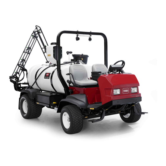
- Page 1 Form No. 3398-905 Rev C Multi Pro ® 5800-G Turf Sprayer with ExcelaRate™ Spray System Model No. 41394—Serial No. 316000001 and Up *3398-905* C Register at www.Toro.com. Original Instructions (EN)
- Page 2 Whenever you need service, genuine Toro parts, or additional information, contact an Authorized Service Dealer or Toro Customer Service and have the model © 2019—The Toro® Company Contact us at www.Toro.com. 8111 Lyndale Avenue South...
-
Page 3: Table Of Contents
Contents Checking the Fuel Line and Connections..........58 Servicing the Fuel Filter ........58 Safety ............... 4 Draining the Fuel Tank ........61 Safe Operating Practices........4 Bleeding the Fuel System ......... 61 Chemical Safety ..........5 Electrical System Maintenance ......61 Operating............ -
Page 4: Safety
Safety • Become familiar with the safe operation of the equipment, operator controls, and safety signs. • All operators and mechanics should be trained. Improper use or maintenance by the operator or The owner is responsible for training the users. owner can result in injury. -
Page 5: Chemical Safety
Chemical Safety • Never spray while people, especially children or pets are nearby. • Before operating the sprayer, always check the WARNING designated areas of the sprayer that are stated in Chemical substances used in the the Pre-Starting Checks in the Operation section. spreader-sprayer system may be hazardous If the machine does not function correctly or is damaged in any way, do not use the sprayer. -
Page 6: Operating
• Handle chemicals in a well ventilated area. – Slow down before turning. Do not attempt sharp turns or abrupt maneuvers or other • Have clean water available especially when filling unsafe driving actions that may cause a loss the spray tank. of sprayer control. -
Page 7: Maintenance
Grip the steering wheel loosely around the Note: For each machine covered in this Operator’s perimeter. Keep your hands clear of the steering Manual, a cab installed by Toro is a ROPS. wheel spokes. • Do not remove the ROPS from the machine. - Page 8 • Do not adjust the traction control speed. To ensure safety and accuracy, have an Authorized Toro Distributor check the ground speed. • Keep your body and hands away from pin hole leaks or nozzles that eject high pressure fluid. Use cardboard or paper to find leaks.
-
Page 9: Safety And Instructional Decals
Safety and Instructional Decals Safety decals and instructions are easily visible to the operator and are located near any area of potential danger. Replace any decal that is damaged or lost. decal93-6686 93–6686 1. Hydraulic oil 2. Read the Operator's Manual. - Page 10 decal107-8732 107-8732 1. Warning—read the Operator's Manual. 2. Torque lug nuts to 95 to 122 N∙m (75 to 90 ft-lb). decal117-2718 decal133-2758 117–2718 133-2758 1. Tec Logic—2 A 8. Tec power—7.5 A 2. Tec power—7.5 A 9. Cruise control—10 A 3.
- Page 11 decal120-0625 120-0625 decal120-0622 1. Pinch point, hand—keep hands away. 120-0622 1. Warning—read the Operator's Manual. 2. Warning—do not enter the tank. 3. Caustic liquid/chemical burn and toxic gas inhalation hazards—wear hand, skin, eye, and respiratory protection. decal107-8722 107-8722 1. Engaging the parking brake—1) Push down on the parking brake pedal;...
- Page 12 decal120-0619 120-0619 1. Warning—read the Operator's Manual. 5. Tipping hazard—do not turn sharply while traveling fast, drive slowly when turning; use caution and drive slowly when traveling across or up and down slopes. 2. Warning—do not operate this machine unless you are trained. 6. To start the engine, engage the parking brake, insert the ignition key and turn it to the start position.
- Page 13 decal127-6982 127-6982 2. Boom spray 1. Pump-return flow decal132-7689 132-7689 1. Auto 7. Rinse system—off 2. Spray mode 8. Sonic sensor—on 3. Manual spray mode 9. Sonic sensor—off 4. Foam marker—on 10. Application rate—increase 5. Foam marker—off 11. Application rate—decrease 6.
- Page 14 decal132-7695 132-7695 1. Pump—on 5. Speed control—on 9. Lower the right boom. 13. Left boom spray 2. Pump—off 6. Speed control—off 10. Raise the right boom. 14. Center boom spray 3. Agitation—on 7. Lower the left boom. 11. Engine speed—fast 15.
-
Page 15: Setup
Important: This sprayer is sold without nozzles. To use the sprayer, you must obtain and install nozzles. Contact your Authorized Toro Distributor for information on the available boom kit and accessories. After you install your nozzles and before using the sprayer for the first time, adjust the boom bypass valves so that the pressure and application rate remains the same for all booms when you turn one or more booms off. -
Page 16: Removing The Shipping Bumper
Removing the Shipping Bumper No Parts Required Procedure Remove the bolts, washers, and nuts that secure the shipping bumper to the front chassis plate (Figure g002332 Figure 3 1. Boom-hinge spring 2. Jam nut Repeat the procedure for each spring on both boom hinges. -
Page 17: Product Overview
Product Overview g032456 Figure 5 1. Passenger seat 4. Rollover Protection System (ROPS) 7. Pump 2. Operator’s seat 5. Tank lid 8. Battery 3. Fresh-water tank 6. Chemical tank 9. Work lights g032457 Figure 6 1. Boom-control cylinder 4. Fuel tank 7. -
Page 18: Controls
Controls g032467 Figure 7 1. Work-light switch 6. Storage compartment 2. Steering wheel 7. InfoCenter 3. Pressure gauge 8. Quick Find™ console 4. Fuel gauge 9. Arm rest 5. Passenger-hand hold 10. Ignition switch Vehicle Controls position while pressing traction pedal slightly to keep the engine speed high. - Page 19 g032468 Figure 8 1. Parking-brake pedal 3. Traction pedal 2. Brake pedal g032469 Figure 9 1. Center console 3. Throttle lever Brake Pedal 2. Speed-lock switch Use the brake pedal to stop or slow the machine (Figure Throttle Lever CAUTION The throttle lever, located on the control panel If you operate the sprayer with poorly adjusted between the seats...
- Page 20 Sprayer Controls g033029 Figure 10 1. Pressure gauge 7. Left boom switch 2. Spray-mode switch 8. Master boom switch 3. Tank-agitation switch 9. Left raise/lower-boom switch 4. Right raise/lower-boom switch 10. Pump switch 5. Right boom switch 11. Application-rate switch 6.
- Page 21 Raise/Lower-Boom Switch The raise/lower-boom switches are located on the center console to the right of the seat and used to raise or lower the left and right booms (Figure 10). Agitation Switch The agitation switch is located on the center console to the right of the seat (Figure 10).
- Page 22 Anti-Siphon Fill Receptacle Located toward the front of the tank cover, is a hose receptacle with a threaded fitting, a 90-degree barbed fitting, and a short hose, which you can direct toward the tank opening. This receptacle allows you to connect a water hose to it and fill the tank with water without contaminating the hose with the chemicals in the tank.
- Page 23 InfoCenter Home Screen Note: The following figure is an example screen; this screen is meant to show all of the potential icons that When you start the machine, the home screen could appear on the screen while operating. appears, displaying the corresponding icons that Refer to the following graphic for all of the icon apply (i.e., the parking brake is engaged, the boom meanings...
-
Page 24: Infocenter Main Menu Screen
InfoCenter Main Menu Screen Note: In Auto mode, the target-application rate should align with the active-application rate. Press and hold the button 5 (far right) on the InfoCenter to access the Main Menu screen. Vehicle-Speed Indicator From the Main Menu screen, you can access the Set The vehicle-speed indicator displays the current Rates screen, Settings screen, Calibration screen, vehicle speed... - Page 25 Set Rates Screen To access the Set Rates screen, press button 2 on the Main Menu screen (Figure 16) until you reach Set Rates and press button 4 to select Set Rates (Figure 17). This screen displays and allows you to set the Target Rate, Rate 1, Rate 2, and the Boost-rate percentage.
- Page 26 Changing Unit of Measure Press button 2 on the Settings screen until you reach Display settings and then press button 4 to select Display (Figure 19). Press button 1 or 2 until you reach Units and then press button 4 to select Units. Press button 1 or 2 until you reach the desired unit and then press button 4 to select this unit.
- Page 27 Changing the InfoCenter Protected Menus Press button 2 on the Display settings screen until you reach Protected Menus, then press button 4 to select Protected Menus (Figure 22). g034290 Figure 24 Enter your PIN using buttons 1 to 4 and press button 5 when you complete the PIN (Figure 25).
- Page 28 g034291 Figure 26 g034306 Figure 28 Changing the InfoCenter PIN 1. Digit 1 4. Digit 4 2. Digit 2 5. Enter PIN Press button 2 on the Display settings screen 3. Digit 3 until you reach PIN Settings, then press button 4 to select PIN Settings (Figure 24).
- Page 29 Calibration Screen To access the Calibration screen, press button 2 on the Main Menu screen (Figure 16) until you reach Calibration, and press button 4 to select Calibration. Note: Pressing button 5 at any time cancels calibrations. If you do so, the machine will automatically use the current calibration rates.
- Page 30 Note: It is recommended to start the 15 second catch test at 2.75 bar (40 psi), then adjust from there. All boom sections must be on when performing the catch test. Start at 2.75 bar (40 psi) and use the application-rate switch to adjust the spray pressure so a catch test yields the volume displayed for the selected nozzle color.
- Page 31 Service Screen Diagnostics Screen To access the Service screen, press button 2 on the To access the Diagnostics screen, press button 2 on Main Menu screen (Figure 16) until you reach Service, the Main Menu screen (Figure 16) until you reach and press button 4 to select Service.
- Page 32 About Screen To access the About screen, press button 2 on the Main Menu screen (Figure 16) until you reach About, and press button 4 to select About (Figure 36). This screen displays the model number and serial number of your machine. g034285 Figure 36...
- Page 33 InfoCenter Spray-Area Screens From the Home screen, press and hold button 5 to open the menu bar and select the Total Area or Sub-Area screen (Figure 37). Use the Total Area screen to track the total number of acres and gallons that you have sprayed across all areas (Figure 37).
- Page 34 InfoCenter Advisories Operator advisories automatically display on the InfoCenter screen when a machine function requires additional action. For example, if you attempt to start the engine while pressing the traction pedal, an advisory displays, indicating that the traction pedal must be in the N position.
-
Page 35: Specifications
Optional Equipment If any of the above items are not correct, notify your The Toro Company has optional equipment and mechanic or check with your supervisor before taking accessories that you can purchase separately and the sprayer out for the day. -
Page 36: Preparing To Drive The Machine
Preparing to Drive the Adding Fuel Machine DANGER In certain conditions, gasoline is extremely Checking the Engine-Oil Level flammable and highly explosive. A fire or explosion from gasoline can burn you and Before you start the engine and use the machine, others and can damage property. -
Page 37: Preparing To Use The Sprayer
Filling the Fuel Tank DANGER In certain conditions during fueling, static Fuel tank capacity: approximately 45 L (12 US gallons). electricity can be released causing a spark which can ignite the gasoline vapors. A fire Park the machine on a level surface, set the or explosion from gasoline can burn you and parking brake, stop the pump, stop the engine, others and can damage property. -
Page 38: Operating The Machine
Inspecting the Tank Straps Service Interval: Before each use or daily—Check the tank straps. Important: Over tightening the tank-strap fasteners can result in deforming and damaging the tank and straps. Fill the main tank with water. Check to see if there is any movement between the tank straps and the tank (Figure 43). -
Page 39: Breaking In A New Sprayer
Note: If the engine requires additional preheating, The light on the switch turns off and the turn the key to the O position, then to the traction control returns to the traction pedal. position. REHEAT Stopping the Engine Note: Repeat steps through as required. -
Page 40: Filling The Fresh-Water Tank
CAUTION Chemicals are hazardous and can cause personal injury. • Read the directions on the chemical labels before handling the chemicals and follow all manufacturer recommendations and precautions. • Keep chemicals away from your skin. Should contact occur, wash the affected area thoroughly with soap and clean water. -
Page 41: Operating The Booms
Important: Prior to introducing wettable immediately put back into the transport cradle. powders into any Toro Spray System mix the powders in a suitable container with Important: The booms can be damaged by... -
Page 42: Taking Proper Turf Care Precautions While Operating In Stationary Modes
Toro recommends using the approved Clean Rinse Kit under the vehicle. for this machine. Contact your Authorized Toro Dealer for more information. - Page 43 Lower the booms into the spray position. Start the engine and move the throttle lever to a higher idle. Ensure that the agitation switch is in the O position. Set the pump switch to the O position and use the application-rate switch to increase the g028158 pressure to a high setting.
-
Page 44: Setting The Boom-Section-Bypass Valves
Setting the Note: The numbered indicators on the bypass knob and needle are for reference only. Boom-Section-Bypass Valves Manual Mode Only Important: When operating in Auto mode, the boom-sections-bypass shutoff valve muse be closed. Before using the sprayer for the first time, if you change the nozzles, or as needed, calibrate the sprayer flow, speed, and set the boom-section bypass (if operating in Manual mode);... -
Page 45: Calibrating The Agitation-Bypass Valve
g028228 Figure 48 1. Open 3. Intermediate position g032532 Figure 49 2. Closed (0) 1. Actuator (agitation valve) 2. Agitation-bypass valve Calibrating the Turn the pump switch to the O position. Move the throttle lever to the I position Agitation-Bypass Valve and turn the key switch to the O position. -
Page 46: Transporting The Sprayer
Transporting the Sprayer Towing the Sprayer For moving the sprayer long distances, use a trailer. In case of an emergency, the sprayer can be towed Secure the sprayer to the trailer. Also, ensure that for a short distance after you open the tow valve. the booms are tied down and secure. - Page 47 g002213 Figure 54 1. Front towing points g002214 Figure 55 1. Rear towing points Release the parking brake. Tow the sprayer at less than 4.8 kph (3 mph). When finished, close the tow valve and torque it to 7 to 11 N∙m (5 to 8 ft-lb).
-
Page 48: Maintenance
Maintenance Recommended Maintenance Schedule(s) Maintenance Service Maintenance Procedure Interval • Replace the hydraulic-fluid filters. After the first 5 hours • Torque the wheel-lug nuts. • Change the rear planetary-gearbox fluid. After the first 8 hours • Check the fan/alternator belt. •... -
Page 49: Daily Maintenance Checklist
Download a free copy of the electrical or hydraulic schematic by visiting www.Toro.com and searching for your machine from the Manuals link on the home page. Daily Maintenance Checklist Duplicate this page for routine use. Maintenance Check Item For the week of:... -
Page 50: Notation For Areas Of Concern
Notation for Areas of Concern Inspection performed by: Item Date Information CAUTION If you leave the key in the starter switch, someone could accidently start the engine and seriously injure you or other bystanders. Remove the key from the starter switch before you do any maintenance. Pre-Maintenance Procedures Jacking the Sprayer Up... -
Page 51: Accessing The Engine
Accessing the Engine Align the holes in the forward heat shield with the threaded holes in the chassis (Figure 59). Assemble the forward heat shield to the machine Removing the Forward Heat Shield with the 6 hex-head bolts and 6 washers (Figure 59) that you removed in step Removing the... -
Page 52: Lubrication
Greasing the Sprayer Service Interval: Every 50 hours—Lubricate the pump. Every 50 hours/Yearly (whichever comes first) Grease Type: No. 2 lithium grease. Toro Premium All-Purpose Grease is available from your Toro Distributor. Wipe the grease fitting clean so that foreign matter cannot be forced into the bearing or bushing. -
Page 53: Greasing The Actuator-Rod Bearings
g013780 Figure 64 g002014 Figure 63 1. Actuator 4. Cotter Right Boom 2. Actuator rod 5. Pin 3. Boom-pivot-pin housing 1. Grease fitting Manipulate the actuator-rod-bearing end and Wipe off excess grease. apply grease into the bearing (Figure 65). Repeat the procedure for each boom pivot. Note: Wipe off excess grease. -
Page 54: Engine Maintenance
Engine Maintenance Repeat the procedure for each actuator-rod bearing. Checking the Air Cleaner Service Interval: Before each use or daily Service the air cleaner more frequently if operating conditions are extremely dusty or sandy. Set the parking brake, stop the pump, stop the engine, and remove the key from the starter switch. - Page 55 Note: Do not clean the air-filter element if it is dirty; replace the air-filter element if it is dirty. Install the dust cap onto the air-cleaner body and secure the cap with the 2 latches (Figure 66). Note: Ensure that the dust valve aligns between the 5 to 7 o’clock position when viewed from the end.
-
Page 56: Servicing The Engine Oil
0°C to 20°C (32°F to -4°F) SAE10W or SAE10W-30 3. Dip stick 1. Front of the machine Toro Premium Engine Oil is available from your 2. Oil-filler cap distributor in either 15W40 or 10W30 viscosity. Refer to the Parts Catalog for part numbers. - Page 57 Changing the Engine-Oil Filter Changing the Engine Oil Align a drain pan under the drain plug (Figure Remove the forward heat shield; refer to 69). Removing the Forward Heat Shield (page 51). Remove the drain plug (Figure 69) and allow the Raise the seats.
-
Page 58: Checking The Pcv Valve
Fuel System Slowly add additional specified oil to bring the oil level to the full mark on the dipstick (Figure 70). Maintenance Important: Overfilling the engine with oil may cause damage to the engine. DANGER Install the oil-filler cap into the filler neck and the dipstick into the dipstick tube (Figure 70). - Page 59 Rotate the nut for the fuel pump/sending unit counterclockwise and remove the nut and seal (Figure Carefully lift and rotate the fuel pump/sending unit out of the neck of the fuel tank (Figure 73). Important: Use caution when handling the fuel pump/sending unit to avoid damaging the arm for the float of the sending unit.
- Page 60 Replacing the Fuel Filter Installing the Fuel Pump and Sending Unit Remove the pickup tube of the fuel filter from the fitting of the fuel pump (Figure 74). Support the float arm and pickup tube together and slip the float and fuel filter into the opening Note: Discard the fuel filter.
-
Page 61: Draining The Fuel Tank
Draining the Fuel Tank Electrical System Maintenance Service Interval: Every 400 hours/Yearly (whichever comes first) Drain and clean the fuel tank if the fuel system Replacing the Fuses becomes contaminated or if you plan to store the machine for an extended period. When cleaning the The fuse block for the electrical system is located fuel tank, use fresh, clean fuel to flush out the tank. -
Page 62: Servicing The Battery
Servicing the Battery WARNING Incorrect battery cable routing could damage the sprayer and cables causing WARNING sparks. Sparks can cause the battery gasses to explode, resulting in personal CALIFORNIA injury. Proposition 65 Warning • Always disconnect the negative Battery posts, terminals, and related accessories contain lead and lead (black) battery cable before compounds, chemicals known to... -
Page 63: Drive System Maintenance
Charging the Battery Drive System Important: Always keep the battery fully charged. Maintenance This is especially important to prevent battery damage when the temperature is below 32°F (0°C). Inspecting the Wheels/Tires Remove the battery from the chassis; refer to Removing the Battery (page 62). -
Page 64: Adjusting The Front Wheel Toe-In
Adjusting the Front Wheel Toe-in Service Interval: Every 200 hours/Yearly (whichever comes first) The toe-in should be 0 to 3 mm (0 to 1/8 inch). Check and fill all tires; refer to Checking the Tire Pressure (page 36). Measure the distance between both of the front tires at the axle height at both the front and rear of the front tires (Figure... -
Page 65: Cooling System Maintenance
Cooling System Tighten the tie rod jam nuts when the adjustment is correct. Maintenance Ensure that there is full travel of the steering wheel in both directions. Servicing the Cooling System Service Interval: Every 100 hours—Check the cooling-system hoses for wear and damage. - Page 66 When the engine is cool, remove the radiator (Figure 82). Place a large drain pan under the radiator. Open the drain valve and drain the coolant into the pan (Figure 83). g028232 Figure 82 1. Radiator cap 3. Expansion-tank cap g002252 Figure 83 2.
-
Page 67: Brake Maintenance
Brake Maintenance Belt Maintenance Adjusting the Brakes Servicing the Alternator Belt If the brake pedal travels more than 2.5 cm (1 inch) before you feel resistance, adjust the brakes as Service Interval: After the first 8 hours follows: Every 100 hours Position the sprayer on a level surface, stop the pump, stop the engine, and remove the key from Check the condition and tension of the... -
Page 68: Hydraulic System Maintenance
(55 US gallons) drums. See the parts catalog or your Authorized Toro Distributor for part numbers. Alternate hydraulic fluids: If the Toro fluid is not available, other fluids may be used provided they meet all the following material properties and industry specifications. -
Page 69: Servicing The Hydraulic Fluid
Replacing the Hydraulic-Fluid Filters Service Interval: After the first 5 hours Every 400 hours/Yearly (whichever comes first) Use the Toro replacement filter (See your Parts Manual for the correct part number.) Important: Use of any other filter may void the g014217 warranty on some components. - Page 70 Changing the Hydraulic Fluid Service Interval: Every 400 hours/Yearly (whichever comes first) Hydraulic-fluid capacity: 56 L (15 US gallons) of the specified hydraulic fluid or equivalent; refer to Servicing the Hydraulic Fluid (page 69). Important: Using any other fluid may void the warranty on some components.
-
Page 71: Sprayer System Maintenance
Sprayer System Dispose of the used fluid at a certified recycling center. Maintenance Checking the Hydraulic Lines and WARNING Hoses Chemical substances used in the spray Inspect the hydraulic lines and hoses daily for system may be hazardous and toxic to you, leaks, kinked lines, loose mounting supports, wear, bystanders, animals, plants, soils or other loose fittings, weather deterioration, and chemical... -
Page 72: Changing The Pressure Filter
Changing the Pressure Install the plug into the bowl hand tight (Figure 91). Filter Service Interval: Every 400 hours Move the machine to a level surface, shut off the sprayer pump, shut off the engine, and remove the key from the starter switch. Align a drain pan under the pressure filter (Figure 91). -
Page 73: Spray System Schematic
Spray System Schematic g034336 Figure 92... -
Page 74: Pump Maintenance
94). (see an Authorized Toro Service Distributor). Every 400 hours/Yearly (whichever comes first)—Inspect the pump check valves and replace if necessary. (see an Authorized Toro Service Distributor). Note: The following machine components are considered parts subject to consumption through use unless found defective and are not covered by the Warranty associated with this machine. -
Page 75: Inspecting The Pivot Bushings
Inspecting the Pivot Cleaning Bushings Cleaning the Service Interval: Every 400 hours/Yearly (whichever Radiator-Cooling Fins comes first) Position the sprayer on a level surface, set the Service Interval: Every 200 hours—Clean the parking brake, stop the pump, stop the engine, radiator fins. - Page 76 Removing the Agitation-Manifold Installing the Section-Manifold Valve (page Valve Installing the Valve Actuator (page 81) Remove the clamps, gaskets, quick connect, and quick-connect pin that secure the manifold for the agitation valve to the agitation-bypass Removing the Valve Actuator valve, pressure-filter head, reducer coupling, Position the sprayer on a level surface, set the and adapter fitting (agitation-throttle valve) as parking brake, stop the pump, stop the engine,...
- Page 77 Removing the Section-Manifold Valve Remove the clamps and gaskets that secure the manifold for the section valve to the adjacent section valve (if left, section valve and the reducer coupling) as shown in Figure g032548 Figure 100 1. Retainer 3. Manifold-valve assembly 2.
- Page 78 Cleaning the Manifold Valve Position the valve stem so that it is in the closed position (B of Figure 102). g027562 Figure 102 1. Valve open 2. Valve closed Remove the end-cap-fitting assemby and quick connect from each end of the manifold body g032550 (Figure 103 Figure...
- Page 79 Assembling the Manifold Valve Check the condition of the outlet fitting O-rings (section-valve manifold only), end cap O-rings, back seating O-rings, ball seat for damage or wear (Figure 103 Figure 104). Note: Replace any damaged or worn O-rings or seats. Apply grease to the valve stem and insert it into the valve-stem seat (Figure 103...
- Page 80 Installing the Agitation-Manifold Align a gasket between the flanges of the agitation-valve manifold and the reducer Valve coupling (B ofFigure 106). Align the flange of the agitation-bypass valve, Assemble the agitation-valve manifold, gasket, a gasket, and the end-cap-fitting flange of the and reducer coupling with a clamp tightened agitation-valve manifold (A of Figure...
-
Page 81: Storage
Storage Secure the end-cap fitting to the outlet fitting by inserting a retainer into the socket of the outlet fitting (A of Figure 107). Position the sprayer on a level surface, set the Align a gasket between the flanges of the parking brake, stop the pump, stop the engine, reducer coupling and the section-valve manifold and remove the key from the starter switch. - Page 82 Note: Check the brakes; refer to Checking the Do not connect the battery cables Brakes (page 36). to the battery posts during storage. Service the air cleaner; refer to Checking Remove the key from the starter switch the Air Cleaner (page 54).
-
Page 83: Troubleshooting
Troubleshooting Troubleshooting the Engine and Vehicle Problem Possible Cause Corrective Action The starter does not rotate the engine. 1. The electrical connections are 1. Check the electrical connections for corroded or loose. good contact. 2. A fuse is blown or loose. 2. - Page 84 Problem Possible Cause Corrective Action The engine loses power. 1. The crankcase-oil level is incorrect. 1. Fill or drain to the Full mark. 2. The air-cleaner element is dirty. 2. Replace.the air-cleaner element. 3. Dirt, water, or stale fuel is in the fuel 3.
- Page 85 Problem Possible Cause Corrective Action A boom actuator is not operating properly. 1. A thermal breaker in the fuse block 1. Wait for the system to cool down before responsible for powering the actuator resuming operation. If the thermal has tripped due to overheating. breakers trip repeatedly, contact your Authorized Service Dealer.
- Page 86 Notes:...
- Page 87 Notes:...
- Page 88 Countries Other than the United States or Canada Customers who have purchased Toro products exported from the United States or Canada should contact their Toro Distributor (Dealer) to obtain guarantee policies for your country, province, or state. If for any reason you are dissatisfied with your Distributor's service or have difficulty obtaining guarantee information, contact the Toro importer.