
Related Manuals for Toshiba FT-8801A


Summary of Contents for Toshiba FT-8801A
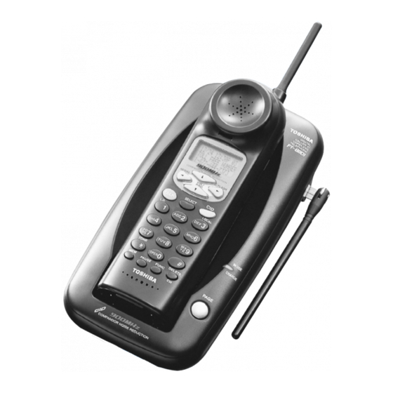
- Page 1 FILE NO. 2BO-200112 SERVICE MANUAL CORDLESS TELEPHONE FT-8801A PUBLISHED IN JAPAN, Sep., 2001...
-
Page 2: Table Of Contents
CONTENTS SAFETY PRECAUTIONS ........................1 OPERATING CONTROLS ........................2 ALIGNMENT PROCEDURE ........................3 BLOCK DIAGRAMS ..........................7 SCHEMATIC DIAGRAMS ........................9 TROUBLESHOOTING HINTS ......................13 IC AND TRANSISTOR VOLTAGE CHART ..................20 SEMICONDUCTOR LEAD IDENTIFICATION ..................24 ELECTRICAL PARTS LOCATION ...................... 27 WIRING DIAGRAMS.......................... -
Page 3: Operating Controls
OPERATING CONTROLS HANDSET CONTROLS Dot matrix display Antenna Number of calls LCD Display Date Time VOL/RING Button FLASH Button Caller's telephone number COMPANDOR NOISE REDUCTION REDIAL FLASH Caller's name REDIAL Button VOL/ RING SELECT Button TALK Button SELECT CID Button L.D. -
Page 4: Alignment Procedure
ALIGNMENT PROCEDURE Base Unit Transmitter Section Connections BASE Unit AF GEN. Test Point Power Meter DC IN TEL Line 1kHz -11dBm 9V Jack Jack Test Point Frequency Counter AC 120V Adapter 60Hz Deviation Meter Preset a) Connect the AC adapter to the base unit while pressing the “PAGE” key, and keep pressing it continuously for approximate 2 seconds. - Page 5 Receiver Section Connections BASE Unit AC Voltmeter RF SG Dummy Load (600-ohms) TEL Line Test Point Jack DC Voltmeter DC IN 9V Jack Terminal AC 120V 60Hz Adapter Preset a) Connect the AC adapter to the base unit while pressing the “PAGE” key, and keep pressing it continuously for approximate 2 seconds.
- Page 6 Handset Unit Transmitter Section Connections HANDSET Unit AF GEN. Test Point Power Meter J603 Battery 1kHz 9mV MIC+Pin Connector Test Point Frequency Counter DC Power Supply Deviation Meter DC 3.8V Preset a) Connect DC power supply to battery connector on the handset unit. b) Turn the DC power supply on while pressing “...
- Page 7 Receiver Section Connections HANDSET Unit AC Voltmeter RF SG Dummy Load (150-ohms) Connector Test Point DC Power Supply J601 DC Voltmeter Battery Terminal Connector DC 3.8V Preset a) Connect DC power supply to battery connector on the handset unit. b) Turn the DC power supply on while pressing “ ∗ ” and “ # ” keys, and keep pressing the keys continuously for approximate 2 seconds.
-
Page 8: Block Diagrams
BLOCK DIAGRAMS Base Unit — 7 —... - Page 9 Handset Unit — 8 —...
-
Page 10: Schematic Diagrams
SCHEMATIC DIAGRAMS Base Unit — 9 — — 10 —... - Page 11 Handset Unit — 11 — — 12 —...
-
Page 12: Troubleshooting Hints
TROUBLESHOOTING HINTS 1. The bell does not ring. See 2. The bell does not ring When the PAGE SW of the & page does not ring. base is pressed, does the ringer on the handset ring? When the TEL SG is joined Check IC3 and TEL network with the base to make bell circuit. - Page 13 2. The bell does not ring & page does not ring. Can the base and handset be See 3. The base and handset connected? cannot be connected. Press handset DIAL key When the key of the handset is Check IC608. while in TALK MODE.
- Page 14 3. The base and handset cannot be connected. Check whether the base Check IC6 and its is able to set in the test peripheral circuit. mode 1. Check the TX POWER Check RT1, Q4, IC1 and and the TX FREQUENCY their peripheral circuits.
- Page 15 Check RT602, R668, Press 3 key, check Check whether there is a R712, R713, R716, R717, whether deviation of the 250 Hz data waveform at TX data is app. 8 kHz RT602. C719 and C748. Dev. Check IC601, D603, and their peripheral circuits.
- Page 16 4. Cannot make a phone call (pulse). Can the base and handset See 3. The base and handset be connected? cannot be connected. While in TALK MODE, press Check IC6. dial key of the handset. Check whether square waveform from Pin 13 of IC6 is fed.
- Page 17 6. Voice cannot be transmitted to other party (outgoing call). Can the base and handset be See 3. The base and handset connected? cannot be connected. The 1 kHz, 9.0mV sine Check C630 and its wavefor m i s a p p l i e d t o peripheral circuit.
- Page 18 7. The voice of the caller cannot be heard (incoming call). Can the base and handset be See 3. The base and handset connected? cannot be connected. The 1 kHz, 219mV(−11dBm) Check the base TEL-line sine waveform is applied to circuit and REPLAY control TEL-line of the base, can circuit.
-
Page 19: Ic And Transistor Voltage Chart
IC AND TRANSISTOR VOLTAGE CHART Transistors Unit [V] Unit [V] Ref. Ref. STBY Note TALK Note STBY Note TALK Note Q603 Q604 Q605 Q608 Q609 Q610 Q611 10.8 DC Jack DC Jack Q612 Q613 GND(digital) GND(digital) Q614 10.8 Q615 Q616 Q601 Q602 —... - Page 20 IC's Unit [V] Unit [V] Ref. Ref. STBY Note TALK Note STBY Note TALK Note 6.1-4.8 6.0-4.7 5.3-4.5 5.3-4.5 Tx Vcont Tx Vcont 3.0-2.6 Ref OSC 3.0-2.6 Ref OSC 4.6-4.2 2.3-1.8 OPEN 2.3-1.7 OPEN 2.2-1.8 OPEN 2.2-1.8 OPEN 5.6-5.4 5.6-5.4 3.8-1.0 2.4-1.8 2.7-0.0...
- Page 21 Unit [V] Unit [V] Ref. Ref. STBY Note TALK Note STBY Note TALK Note OPEN OPEN OPEN OPEN OPEN OPEN 2.9-0.0 DATA(PULSE) DATA(PULSE) OPEN OPEN 2.9-0.0 DATA(PULSE) DATA(PULSE) OPEN OPEN 2.9-0.0 DATA(PULSE) DATA(PULSE) IC601 Rx Vcont Rx Vcont OPEN OPEN OPEN OPEN OPEN...
- Page 22 Unit [V] Unit [V] Ref. Ref. STBY Note TALK Note STBY Note TALK Note OPEN OPEN IC603 OPEN OPEN IC605 Vbatt Vbatt OPEN OPEN Vbatt Vbatt IC606 GND(digital) GND(digital) Vbatt Vbatt OPEN OPEN 2.9-0.0 DATA(PULSE) DATA(PULSE) 2.9-0.0 DATA(PULSE) DATA(PULSE) 2.9-0.0 DATA(PULSE) DATA(PULSE) IC607...
-
Page 23: Semiconductor Lead Identification
SEMICONDUCTOR LEAD IDENTIFICATION DIODES 1N4148 1SS226 EL-1254ID HZ4B1 Anode/Cathode HZ33-2 HZ7B1 HZ11A Anode Cathode Anode Cathode Cathode Anode HZK6C 1SS294 EMPG4868K Cathode Cathode Anode Anode (Open) Cathode Anode HVC355B MM4148 Cathode Anode Cathode Anode TRANSISTORS MT4S06U HSD471A-Y 2SC3052 2SC5344Y 2SC5065 2SA1235A B: Base B: Base... - Page 24 IC's IC2/IC602 IC1/IC601 LA8634VU M64884FP-C60J TXGND1 MIXIN LPF1 IN PRE. IN LPF1 OUT PRE. NF TXOUT MIXGND EXP. IN CMP. NF RXVCC EXT. VREC CMP. VREC TXVCC INT. OUT CMP. OUT TEL. OUT LPF2 IN V. HOLD LPF2 OUT INTC. CONT CMP.
- Page 25 XC61CC4502PR IC605 IC606 RH5RE32AA XC612N3328MR DET1 DET2 I N1 I N2 IC607 IC608 NJM2870F03 MB89538LPFM CONT NOI SE BYPASS P46/INT26 P47/INT27 Vout THERMAL SENSOR CONT. BANDGAP REFERENCE P60/INT10 P61/INT11 P62/INT12 — 26 —...
-
Page 26: Electrical Parts Location
ELECTRICAL PARTS LOCATION Base Unit Main PCB — 27 —... - Page 27 Handset Unit Main PCB — 28 —...
-
Page 28: Wiring Diagrams
WIRING DIAGRAMS Base Unit — 29 —... - Page 29 Handset Unit — 30 —...
-
Page 30: Exploded View And Mechanical Parts List
EXPLODED VIEW AND MECHANICAL PARTS LIST HANDSET MAIN BASE MAIN PCB ASSY PCB ASSY ANTENNA — 31 —... - Page 31 LOC. PART NO. REF NO. DESCRIPTION RC009836 GNBZ467460Z BUTTON, PUSH RC012305 GCAS374142Z CASE, BOTTOM RC009864 GCAS366561Z CASE, TOP RC009325 HTML446079Z CHARGE TERMINAL C5191(PBP) RC009837 LFUT494200Z FOOT RC009450 GCAS447683Z HOOK RC009871 PLBB468061Z LABEL, BARCODE RC012294 HSDC372505Z SHIELD COVER SPTE RC009313 GCAS446076Z LED LENS PMMA RC012293...
-
Page 32: Parts List
PARTS LIST PRODUCT SAFETY NOTE: Products marked with a have special characteristics important to safety. Before replacing any of these components, read carefully the product safety notice of this service manual. Don’ t degrade the safety of the product through important servicing. Symbol Symbol ±1... - Page 33 LOC. PART NO. REF NO. DESCRIPTION RC005360 BCMM816092Z CERAMIC M/L 6PF 50V D CH RC005222 BCMS811091Z CERAMIC M/L 1PF 50V C CK RC005223 BCMS812091Z CERAMIC M/L 2PF 50V C CK RC005216 BCMM813304Z CERAMIC M/L 33PF 50V J CH RC008292 BCMM811507Z CERAMIC M/L 15PF 50V G CH RC008292...
- Page 34 LOC. PART NO. REF NO. DESCRIPTION C112 RC008294 BCSH116896Z TANTALUM CHIP 6.8UF 10V M C-122 TAPE C113 RC005205 BCML811035Z CERAMIC M/L 0.01UF 50V K B C114 RC005210 BCMM811014Z CERAMIC M/L 100PF 50V J CH C115 RC005210 BCMM811014Z CERAMIC M/L 100PF 50V J CH C116 RC005211 BCMM811204Z...
- Page 35 LOC. PART NO. REF NO. DESCRIPTION C175 RC005216 BCMM813304Z CERAMIC M/L 33PF 50V J CH C176 RC005202 BCML311045Z CERAMIC M/L 0.1UF 16V K B C177 RC008665 BCMM818091Z CERAMIC M/L 8PF 50V C CH C178 RC008665 BCMM818091Z CERAMIC M/L 8PF 50V C CH C180 RC008666 BCMS811591Z...
- Page 36 LOC. PART NO. REF NO. DESCRIPTION C652 RC008293 BCMM819091Z CERAMIC M/L 9PF 50V C CH C653 RC005209 BCMM811002Z CERAMIC M/L 10PF 50V D CH C654 RC005222 BCMS811091Z CERAMIC M/L 1PF 50V C CK C655 RC004412 BCXT312245Z CERAMIC M/L (2125) 0.22UF 16V K B C656 RC005216 BCMM813304Z...
- Page 37 LOC. PART NO. REF NO. DESCRIPTION C707 RC005202 BCML311045Z CERAMIC M/L 0.1UF 16V K B C708 RC005202 BCML311045Z CERAMIC M/L 0.1UF 16V K B C710 RC005202 BCML311045Z CERAMIC M/L 0.1UF 16V K B C711 RC005209 BCMM811002Z CERAMIC M/L 10PF 50V D CH C713 RC005209 BCMM811002Z...
- Page 38 LOC. PART NO. REF NO. DESCRIPTION RC002236 BDAY0246003 AX TS 26+ 1N4148 T-77 RC002236 BDAY0246003 AX TS 26+ 1N4148 T-77 RC002236 BDAY0246003 AX TS 26+ 1N4148 T-77 RC002236 BDAY0246003 AX TS 26+ 1N4148 T-77 RC012276 BDAY1083001 HVC355B TRF RC002236 BDAY0246003 AX TS 26+ 1N4148 T-77 RC002236...
- Page 39 LOC. PART NO. REF NO. DESCRIPTION JACKS RC008992 BJKY1183002 JK-1183 MJ-62J-RD315 RC001094 BJKY0234001 JK-234 DJ13-1 J601 RC001653 BJKY0571001 JK-571 M60-002-020-HKAD COILS RC009749 BLZY0218476 INDUCTOR MOLDED CHIP LZ-218 CIH10T4N7S T 4.7NH RC009744 BLZY0218107 INDUCTOR MOLDED CHIP LZ-218 CIH10T10NJ T 10NH RC012283 BLZY0218566 INDUCTOR MOLDED CHIP LZ-218 CIH10T5N6S T 5.6NH...
- Page 40 LOC. PART NO. REF NO. DESCRIPTION RC012040 BDBC3052106 DB-862 2SC3052-T12-1F RC012040 BDBC3052106 DB-862 2SC3052-T12-1F Q601 RC009280 BDBZ1135001 DB-1135 MT4S06U(TE85L) Q602 RC009280 BDBZ1135001 DB-1135 MT4S06U(TE85L) Q603 RC008760 BDBC5065124 DB-848 2SC5065-Y(TE85R) Q604 RC012040 BDBC3052106 DB-862 2SC3052-T12-1F Q605 RC012040 BDBC3052106 DB-862 2SC3052-T12-1F Q608 RC012038 BDBA1235106 DB-092 2SA1235A-T12-1F...
- Page 41 LOC. PART NO. REF NO. DESCRIPTION RC008735 BRFC166824Z CARBON FIXED CHIP 6.8K 1/16W J TAPE RC005241 BRFC161034Z CARBON FIXED CHIP 10K 1/16W J TAPE RC005283 BRFC162734Z CARBON FIXED CHIP 27K 1/16W J TAPE RC008286 BRFC162744Z CARBON FIXED CHIP 270K 1/16W J TAPE RC005278 BRFC161244Z CARBON FIXED CHIP...
- Page 42 LOC. PART NO. REF NO. DESCRIPTION R108 RC005240 BRFC161024Z CARBON FIXED CHIP 1K 1/16W J TAPE R110 RC005249 BRFC162244Z CARBON FIXED CHIP 220K 1/16W J TAPE R111 RC002327 BRFC016804Z CARBON FIXED CHIP 68 1/10W J TAPE R112 RC005246 BRFC162204Z CARBON FIXED CHIP 22 1/16W J TAPE R113 RC002332...
- Page 43 LOC. PART NO. REF NO. DESCRIPTION R170 RC002899 BRFC180004Z CARBON FIXED CHIP 0 1/8W J TAPE R171 RC005311 BRFC160004Z CARBON FIXED CHIP 0 1/16W J TAPE R172 RC002899 BRFC180004Z CARBON FIXED CHIP 0 1/8W J TAPE R173 RC005242 BRFC161044Z CARBON FIXED CHIP 100K 1/16W J TAPE R176 RC008765...
- Page 44 LOC. PART NO. REF NO. DESCRIPTION R640 RC008027 BRFC161234Z CARBON FIXED CHIP 12K 1/16W J TAPE R641 RC005283 BRFC162734Z CARBON FIXED CHIP 27K 1/16W J TAPE R642 RC005283 BRFC162734Z CARBON FIXED CHIP 27K 1/16W J TAPE R643 RC005285 BRFC165634Z CARBON FIXED CHIP 56K 1/16W J TAPE R644 RC005256...
- Page 45 LOC. PART NO. REF NO. DESCRIPTION R708 RC002332 BRFC018204Z CARBON FIXED CHIP 82 1/10W J TAPE R709 RC002332 BRFC018204Z CARBON FIXED CHIP 82 1/10W J TAPE R710 RC005284 BRFC163334Z CARBON FIXED CHIP 33K 1/16W J TAPE R711 RC005280 BRFC161534Z CARBON FIXED CHIP 15K 1/16W J TAPE R712 RC005242...
-
Page 46: Assembly Parts List
SLEEVE RC009920 WSLV469740Z SLEEVE ASSEMBLY PARTS LIST NOTE: Following part numbers are not available as replacement parts. Order parts necessary for repair or contact the Toshiba Factory Service Center. LOC. PART NO. REF NO. DESCRIPTION RC012300 AC338BHBA+BB MAIN PCB ASSY, BASE... -
Page 47: Specifications
SPECIFICATIONS MEASUREMENT CONDITIONS 1. Standard Voltage: DC 3.8 V ±0.025 V Portable Unit AC 120 V ±3 V 60 Hz Base Unit 25 °C ±5 °C 2. Temperature: 3. Channel: Portable (TX Frequency) Base (TX Frequency) 902.052464 MHz 925.997470 MHz 902.102465 MHz 926.047470 MHz 902.152465 MHz... - Page 48 BASE UNIT RECEIVER Unit Nominal Limit −115 < −107 1. Sensitivity 12 dB SINAD (with CCITT Filter) −1.5 −5.5 ~ 2.5 2. Frequency Response (Ref: 1 kHz) 0.3 kHz −2.5 −6.5 ~ 1.5 3.0 kHz 3. Distortion at 1 mV RF Input <...
- Page 49 PORTABLE UNIT RECEIVER Unit Nominal Limit −115 1. Sensitivity 12 dB SINAD (with CCITT Filter) <−107 2. Frequency Response 0.3 kHz +5.5 1.5 ~ 9.5 −10.0 −14.0 ~ −6.0 (Ref: 1 kHz/5 kHz dev input) 3.0 kHz −10.5 −13.5 ~ −7.5 3.
- Page 50 CALLER ID FSK SENSITIVITY Unit Nominal Limit −46 < −44 1. Minimum Signal Level (with 25 dB S/N Ratio) −12 < 2. Maximum Signal Level (with 25 dB S/N Ratio) OTHERS Ni-Cd Battery 600 mAH (@1.2 V × 3 = 3.6 V) 1.
- Page 51 QUICK SETTING / USING THE PHONE CALLER ID SERVICE CALLER ID CORDLESS TELEPHONE REFERENCE FT-8801A Setting The Dial Mode Setting Up Caller ID Making a Call with Caller ID Data GUIDE Depending on your dialing system, set the mode as follows:...
- Page 52 AJUSTE/UTILIZACIÓN DEL TELÉFONO SERVICIO DE IDENTIFICACIÓN DEL QUE LLAMA REFERENCIA CALLER ID CORDLESS TELEPHONE RÁPIDA FT-8801A Ajuste del modo de marcación Ajuste del dato de identificación del que llama Realización de llamadas con los datos de identificación del que llama Según su sistema de marcación, ajuste el modo de la manera siguiente:...
- Page 53 TOSHIBA AMERICA CONSUMER PRODUCTS, INC. 82 TOTOWA ROAD, WAYNE, N.J. 07470 TOSHIBA HAWAII, INC. 327 KAMAKEE ST., HONOLULU, H.I. 96814...