
Related Manuals for Toshiba FT-8908


Summary of Contents for Toshiba FT-8908
- Page 1 FILE NO. 2B0-9806 SERVICE MANUAL CORDLESS TELEPHONE FT-8908 PUBLISHED IN JAPAN, Oct., 1998...
-
Page 2: Table Of Contents
CONTENTS SAFETY PRECAUTIONS ........................1 OPERATING CONTROLS ........................2 ALIGNMENT PROCEDURE ........................3 BLOCK DIAGRAMS..........................9 SCHEMATIC DIAGRAMS........................14 TROUBLESHOOTING HINTS ......................26 IC AND TRANSISTOR VOLTAGE CHART ..................33 SEMICONDUCTOR LEAD IDENTIFICATION..................40 ELECTRICAL PARTS LOCATION ...................... 46 WIRING DIAGRAMS ........................... 52 EXPLODED VIEW AND MECHANICAL PARTS LIST ................ -
Page 3: Operating Controls
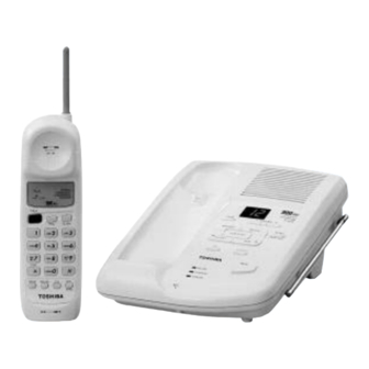
OPERATING CONTROLS HANDSET CONTROLS Antenna TALK/BATT LOW LED (Red) • Standby status : OFF • Lights ON during a phone conversation using the handset. RDL (Redial) button • Blinks when a channel is changed, and during the low battery status. FLASH button TALK button SPEED DIAL INDEX (back) -
Page 4: Alignment Procedure
ALIGNMENT PROCEDURE Test Mode For Base Unit Press the “PAGE” key about 1.5 seconds while turning the power on. 1. To change the TEST mode: Press the “PAGE” key with T/P switch to PULSE position. 2. To change channel: Press the “PAGE” key with T/P switch to TONE position. If changing the step, the channel returns to the start channel. - Page 5 Test Mode For Handset Unit To perform the TEST mode, turn the power ON by pressing the “ ” and “#” buttons at the same time. When entered the TEST mode, the bell rings and the unit enters TEST mode 1 . ( Refer to the following table. ) 1.
-
Page 6: Base Unit
Base Unit Transmitter Section Connection BASE RF PCB BASE MAIN PCB AF GEN. Test Point Power Meter Test Point DC IN TEL Line 1kHz 77.5mV 9V Jack Jack Test Point Frequency Counter AC 120V DC 9V Adapter 60Hz Deviation Meter Preset Place the Base Unit in VCO/TX FREQ ADJ mode in accordance with the procedure on page 3. - Page 7 Receiver Section Connection BASE RF PCB BASE MAIN PCB AC Voltmeter RF SG Dummy Load (600-ohm) − − TEL Line DC IN Jack Test Point 9V Jack DC Voltmeter AF Terminal AC 120V DC 9V 60Hz Adapter Preset Place the Base Unit in RX SENS mode (step 4) in accordance with the procedure on page 3. Alignment Procedure Step Preset to...
-
Page 8: Schematic Diagrams
Handset Unit Transmitter Section Connection HANDSET MAIN PCB HANDSET RF PCB AF GEN. Test Point Power Meter Test Point Battery 1kHz 11.0mV MIC + Pin Terminals Test Point Frequency Counter DC Power Supply Deviation DC 3.8V Meter Preset Place the Handset in VCO/TX FREQ. ADJ mode in accordance with the procedure on page 4. Alignment Procedure Step Adjustment... - Page 9 Receiver Section Connection HANDSET RF PCB HANDSET MAIN PCB AC Voltmeter RF SG Dummy Load (150-ohm) J602 − − Battery Connector Test Point Terminals J601 DC Voltmeter DC Power Supply AF Terminal DC 3.8V Preset Place the Handset in RX SENS mode (step 4) in accordance with the procedure on page 4. Alignment Procedure Step Preset to...
- Page 11 Base, RF — 11 —...
- Page 12 Handset, Main — 12 —...
- Page 13 Handset, RF — 13 —...
-
Page 20: Troubleshooting Hints
TROUBLESHOOTING HINTS 1. The bell does not ring. When the PAGE key of the See 2. The bell does not base is pressed, does the ring & page does not ring. ringer on the handset ring? When the TEL SG is joined Check IC7 and TEL network with the base to make bell circuit. - Page 21 2. The bell does not ring & page does not ring. See 3. The base and Can the base and handset handset cannot be be connected? connected. Press handset DIAL key When the key of the Check IC603. while in TALK MODE. handset is pressed, can the Can key touch sound be pulse output at pin 38 of...
- Page 22 3. The base and handset cannot be connected. Check IC22 and its Check whether the base is peripheral circuit. able to set in the test mode 1. Check the TX POWER and Check base RF unit. the TX FREQUENCY on the base unit.
- Page 23 Set the handset in the test Check whether there is a Check VR601, R619, R632, mode 3, check whether 250Hz data waveform at R634, R635, R636 deviation of the TX data is Pin 9 of J601. and C611. app. 7 kHz Dev. Check handset RF unit.
- Page 24 4. Cannot make a phone call (pulse). See 3. The base and Can the base and handset handset cannot be be connected? connected. While in TALK MODE, Check IC22. press dial key of the handset. Check whether square waveform from pin 13 of IC22 is fed.
-
Page 25: Voice Cannot Be Transmitted To Other Party (Outgoing Call)
6. Voice cannot be transmitted to other party (outgoing call). See 3. The base and Can the base and handset handset cannot be be connected? connected. The 1 kHz, 12.5 mV sine Check Q608 and its waveform is applied to peripheral circuit. - Page 26 7. The voice of the caller cannot be heard (incoming call). See 3. The base and Can the base and handset handset cannot be be connected? connected. Check the base TEL-line The 1 kHz 77.5 mV sine waveform is applied to circuit and RELAY control TEL-line of the base, can the circuit.
-
Page 27: Ic And Transistor Voltage Chart
IC AND TRANSISTOR VOLTAGE CHART Transistors Unit [V] Unit [V] Ref. Ref. STBY TALK Note STBY TALK Note 0.75 0.75 Q201 Q202 Q203 Q206 Q207 Q211 — 33 —... - Page 28 Unit [V] Unit [V] Ref. Ref. STBY TALK Note STBY TALK Note Q212 Q605 Q400 Q606 Q401 Q608 Q402 Q609 Q403 Q610 Q501 Q611 Q502 Q612 VOL NORMAL Q503 Q506 Q507 Q511 Q512 Q601 Q602 Q603 Q604 — 34 —...
- Page 29 IC ’ S Unit [V] Unit [V] Ref. Ref. STBY TALK Note STBY TALK Note IC22 IC11 IC12 IC16 IC20 IC201 IC21 — 35 —...
- Page 30 Unit [V] Unit [V] Ref. Ref. STBY TALK Note STBY TALK Note IC301 IC201 IC302 IC202 IC401 IC402 IC301 — 36 —...
- Page 31 Unit [V] Unit [V] Ref. Ref. STBY TALK Note STBY TALK Note IC403 IC403 IC405 — 37 —...
- Page 32 Unit [V] Unit [V] Ref. Ref. STBY TALK Note STBY TALK Note IC406 IC405 IC407 IC501 IC406 IC502 — 38 —...
- Page 33 Unit [V] Unit [V] Ref. Ref. STBY TALK Note STBY TALK Note IC502 IC603 IC601 IC602 IC604 IC605 IC603 — 39 —...
-
Page 34: Semiconductor Lead Identification
SEMICONDUCTOR LEAD IDENTIFICATION Base Unit D1: HZ7C3 D7/D9/D201: D15/D401: D2/D4/D5/D301/D302 D6: HZ33CP 1SS226 HSM88WA D303/D304: RLS4148 D8/D11/D18/D19: 1N4148 D13/D17: 1N4003 Anode Anode/Cathode Anode D10: HZ7A3 D20: HZ6B2 Cathode Cathode Anode Cathode Cathode Anode Cathode D308: VR1102W D305: LTD-482P D202/D203: 1SV270 D307: BRPG1202W D309: PG1102W Anode... - Page 35 IC6/IC8 IR3N74AN M5223FP OUTPUT1 MUTE MUTE NEGATIVE1 − OUTPUT2 EREC CREC POSITIVE1 NEGATIVE2 − POSITIVE2 VREF IC12 IC7/IC11 IC16: RH5VL47CA TK11232AM IC20: RH5VL35CA LTV-817 IC21: RH5VL33CA IC407: RH5VL45AA CONT NOISE BYPASS IC22: MB89173PF IC405: MB89174APF P36/INT2 DTMF P37/BZ MDD0 P00/L10 MDD1 P01/L11 P02/L12...
- Page 36 IC202 IC201 M64084AGP MC3361CDR2 Mixer MIX REF Input Crystal Osc. Tx OUT MIX IN Mixer Audio Tx Vcc Rx Vcc Output Mute Scan Control Limiter Squelch Input Input Tx GND Rx GND Filter Output Decoupling Filter Input Quad Demodulator Input Audio Xout Lock...
- Page 37 IC403 IC406 1605CJ KM29N040T HD87 SCKA FDB7 FDB6 FDB5 FDB4 FDB3 VROM Chip Enable FDB2 VAB14 VAB15 / CS / CONF2 FDB1 FDB0 VAB16 / CONF0 R / B / DO VAB13 Flash Chip Select / CONF1 VAB12 Read Enable / SK / CONF3 Address Latch Enable / DI VAB11 Command Latch Enable...
- Page 38 Handset D605: S1ZB20 D608: LTL-16KPE D601/D604: RLS4148 − Cathode Anode Cathode Anotde D607: HZK6C D606: HSM88WA D501: 1SS226 D502/D503: 1SV270 Anode Anode/Cathode Cathode Cathode Anode Cathode Q503: 2SC2714 Q501: 2SC4095 Q506/Q507/Q512: 2SC5065 Q601/Q602/Q603/Q604 /Q608/Q610/Q611/Q612: 2SC2712 Q502/Q511/Q605 /Q606/Q609: 2SA1162 B: Base E: Emitter C: Collector IC502...
- Page 39 IC601 IC602 IR3N74AN TK11232AM CONT MUTE MUTE EREC CREC NOISE BYPASS Vout VREF IC603 IC605 MB89174APF RH5VL28CA IC604 RH5VL33CA P36/INT2 DTMF P37/BZ P00/L10 MDD0 MDD1 P01/L11 P02/L12 P03/L13 P04/L14 P05/L15 P50/(X0A) P51(Z1A) P06/L16 P07/L17 — 45 —...
-
Page 40: Electrical Parts Location
ELECTRICAL PARTS LOCATION Base, Main — 46 —... - Page 41 Base, RF — 47 —...
- Page 42 Base, Key — 48 —...
- Page 43 Base, DSP — 49 —...
- Page 44 Handset, Main — 50 —...
- Page 45 Handset, RF — 51 —...
-
Page 46: Wiring Diagrams
WIRING DIAGRAMS Base — 52 —... - Page 47 Handset IC603 SOLDERING PORTABLE RF B501 PE1294DA [TOP VIEW] — 53 —...
-
Page 48: Exploded View And Mechanical Parts List
EXPLODED VIEW AND MECHANICAL PARTS LIST Base Unit Note: To remove the RF Assembly from the unit, remove four screws 24 . Three screws 23 are used for fastening the Shield Cases 26 and 27 . — 54 —... - Page 49 Base Unit LOC. PART NO. REF. NO. DESCRIPTION RC008898 GNBZ358494Z Button, Function RC008897 GCAS458497Z Case, Battery RC008896 GCAS258239Z Case, Bottom RC008895 GCAS158493Z Case, Top RC005686 HTML457884Z Charge Terminal C5191(PBP) RC004860 HTML451849Z Contact Plate C5191(PBP) RC002384 LFUT428079Z Foot BUMPON SJ-5916 1.6T RC005689 LHDZ453179Z Holder, Mic...
- Page 50 Handset Note: To remove the RF Assembly from the unit, remove four screws 69 . Three screws 68 are used for fastening the Shield Cases 70 and 71 . — 56 —...
- Page 51 Handset LOC. PART NO. REF. NO. DESCRIPTION RC008915 RBLD458506Z Blind RC008911 GNBZ458503Z Button, Function RC008912 GNBZ458504Z Button, Push RC008906 GCAS358498Z Case, Front RC008907 GCAS358499Z Case, Rear RC008707 HTML457893Z Charge Terminal C2680(BSP) RC008909 GCAS458501Z Cover, Antenna ELASTOMER RC008908 GCAS458500Z Cover, Battery RC008715 RCUM417955Z Cushion...
-
Page 52: Parts List
PARTS LIST PRODUCT SAFETY NOTE: Products marked with a have special characteristics important to safety. Before replacing any of these components, read carefully the product safety notice of this service manual. Don’ t degrade the safety of the product through important servicing. Symbol Symbol ±... - Page 53 LOC. PART NO. DESCRIPTION RC002233 BCXT814725Z CERAMIC 0.0047UF 50V K B RC002233 BCXT814725Z CERAMIC 0.0047UF 50V K B RC001794 BCAZ111016Z ELECTROLYTIC 100UF 10V M C-156 RC001068 BCXT811025Z CERAMIC 0.001UF 50V K B RC001069 BCXT811035Z CERAMIC 0.01UF 50V K B RC001794 BCAZ111016Z ELECTROLYTIC 100UF 10V M C-156...
- Page 54 LOC. PART NO. DESCRIPTION RC002224 BCXK811040Z CERAMIC 0.1UF 50V Z F RC001068 BCXT811025Z CERAMIC 0.001UF 50V K B RC005398 BCAZ901026Z ELECTROLYTIC 1000UF 6.3V M C-156 C103 RC001069 BCXT811035Z CERAMIC 0.01UF 50V K B C104 RC001068 BCXT811025Z CERAMIC 0.001UF 50V K B C106 RC002229 BCXT511045Z...
- Page 55 LOC. PART NO. DESCRIPTION C241 RC008753 BCMM812098Z CERAMIC 2PF 50V B CH C242 RC005223 BCMS812091Z CERAMIC 2PF 50V C CK C243 RC008757 BCMM818204Z CERAMIC 82PF 50V J CH C244 RC005205 BCML811035Z CERAMIC 0.01UF 50V K B C245 RC005212 BCMM811504Z CERAMIC 15PF 50V J CH C246 RC005212...
- Page 56 LOC. PART NO. DESCRIPTION C299 RC005205 BCML811035Z CERAMIC 0.01UF 50V K B C401 RC008731 BCXK311050Z CERAMIC 1UF 16V Z F C402 RC005210 BCMM811014Z CERAMIC 100PF 50V J CH C404 RC008731 BCXK311050Z CERAMIC 1UF 16V Z F C405 RC005421 BCSS951005Z TANTALUM 10UF 7V K A C-241 C406 RC004185...
- Page 57 LOC. PART NO. DESCRIPTION C509 RC008755 BCMM815098Z CERAMIC 5PF 50V B CH C510 RC005216 BCMM813304Z CERAMIC 33PF 50V J CH C511 RC005212 BCMM811504Z CERAMIC 15PF 50V J CH C512 RC005205 BCML811035Z CERAMIC 0.01UF 50V K B C513 RC005205 BCML811035Z CERAMIC 0.01UF 50V K B C514 RC005205...
- Page 58 LOC. PART NO. DESCRIPTION C555 RC005213 BCMM811804Z CERAMIC 18PF 50V J CH C556 RC005219 BCMM814704Z CERAMIC 47PF 50V J CH C557 RC008758 BCSS116896Z TANTALUM 6.8UF 10V M A C-241 C558 RC005205 BCML811035Z CERAMIC 0.01UF 50V K B C559 RC005217 BCMM813314Z CERAMIC 330PF 50V J CH C560 RC004185...
- Page 59 LOC. PART NO. DESCRIPTION C614 RC002229 BCXT511045Z CERAMIC 0.1UF 25V K B C615 RC004185 BCSS951006Z TANTALUM 10UF 7V M A C-241 C616 RC004185 BCSS951006Z TANTALUM 10UF 7V M A C-241 C617 RC002229 BCXT511045Z CERAMIC 0.1UF 25V K B C618 RC008731 BCXK311050Z CERAMIC 1UF 16V Z F...
- Page 60 LOC. PART NO. DESCRIPTION RC008885 BDAY0492031 ZENER AX TS 26 + HZ6B2 TD D201 RC001635 BDAY0274001 DIODE 1SS226 TE85L D202 RC008759 BDAY0908001 DIODE 1SV270(TPH3) D203 RC008759 BDAY0908001 DIODE 1SV270(TPH3) D301 RC001826 BDAY0433001 DIODE RLS4148 TE11 D302 RC001826 BDAY0433001 DIODE RLS4148 TE11 D303 RC001826 BDAY0433001...
- Page 61 LOC. PART NO. DESCRIPTION IC202 RC008761 BDEY3571003 M64084AGP-601C IC301 RC004218 BDEY2245001 TC74HC4094AF IC302 RC004218 BDEY2245001 TC74HC4094AF IC401 RC005425 BDEY3215001 T7503-1EC IC402 RC005423 BDEY1533003 MC34119D R2 IC403 RC005424 BDEY3214001 1605CJ--ELR30-DB IC405 RC005422 BDDY0627001 UC2087 MB89174APF-G-186-BND IC406 RC008100 FSMEMC402ZL KM29N040T IC407 RC004595 BDEY2486003 RH5VL45AA-T1 IC501...
- Page 62 LOC. PART NO. DESCRIPTION L207 RC005236 BLZY0127686 INDUCTOR LZ-127 0.0068UH TAPE L208 RC004882 BLZY0108826 INDUCTOR LZ-108 0.0082UH K TAPE L209 RC005236 BLZY0127686 INDUCTOR LZ-127 0.0068UH TAPE L211 RC005232 BLZY0080159 INDUCTOR LZ-080 1.5UH K TAPE L212 RC004876 BLFY0274001 COIL LF-274 615LN-0124=P3 L214 RC004878 BLZY0108107...
- Page 63 LOC. PART NO. DESCRIPTION RC003200 BDBD0471111 DB-411 2SD471-L RC003200 BDBD0471111 DB-411 2SD471-L RC001637 BDBC2712303 DB-381 2SC2712-GR TE85L RC001637 BDBC2712303 DB-381 2SC2712-GR TE85L Q201 RC004867 BDBC4095672 DB-810 2SC4095-R47 T1 Q202 RC001081 BDBA1162107 DB-036 2SA1162-G(GR)TE85L Q203 RC002245 BDBC2714124 DB-718 2SC2714-Y TE85L Q206 RC008760 BDBC5065124 DB-848 2SC5065-Y(TE85R)
- Page 64 LOC. PART NO. DESCRIPTION RC002304 BRFC011844Z CARBON 180K 1/10W J TAPING RC002618 BRFC011244Z CARBON 120K 1/10W J TAPING RC002501 BRFC018234Z CARBON 82K 1/10W J TAPING RC002298 BRFC011044Z CARBON 100K 1/10W J TAPING RC002300 BRFC011234Z CARBON 12K 1/10W J TAPING RC002327 BRFC016804Z CARBON 68 1/10W J TAPING...
- Page 65 LOC. PART NO. DESCRIPTION RC004183 BRSJ001024Z METAL OXIDE 1K 1WS J RC002296 BRFC011024Z CARBON 1K 1/10W J TAPING RC002298 BRFC011044Z CARBON 100K 1/10W J TAPING RC002298 BRFC011044Z CARBON 100K 1/10W J TAPING RC002322 BRFC014734Z CARBON 47K 1/10W J TAPING RC002298 BRFC011044Z CARBON 100K 1/10W J TAPING...
- Page 66 LOC. PART NO. DESCRIPTION R136 RC002322 BRFC014734Z CARBON 47K 1/10W J TAPING R138 RC002309 BRFC012254Z CARBON 2.2M 1/10W J TAPING R139 RC002297 BRFC011034Z CARBON 10K 1/10W J TAPING R140 RC002297 BRFC011034Z CARBON 10K 1/10W J TAPING R141 RC002296 BRFC011024Z CARBON 1K 1/10W J TAPING R143 RC002321...
- Page 67 LOC. PART NO. DESCRIPTION R230 RC008765 BRFC161004Z CARBON 10 1/16W J TAPING R231 RC005250 BRFC162704Z CARBON 27 1/16W J TAPING R232 RC005240 BRFC161024Z CARBON 1K 1/16W J TAPING R233 RC008766 BRFC161224Z CARBON 1.2K 1/16W J TAPING R239 RC008767 BRFC163344Z CARBON 330K 1/16W J TAPING R240 RC005256...
- Page 68 LOC. PART NO. DESCRIPTION R337 RC002297 BRFC011034Z CARBON 10K 1/10W J TAPING R354 RC002296 BRFC011024Z CARBON 1K 1/10W J TAPING R355 RC002296 BRFC011024Z CARBON 1K 1/10W J TAPING R356 RC002296 BRFC011024Z CARBON 1K 1/10W J TAPING R357 RC002296 BRFC011024Z CARBON 1K 1/10W J TAPING R359 RC002296...
- Page 69 LOC. PART NO. DESCRIPTION R448 RC005242 BRFC161044Z CARBON 100K 1/16W J TAPING R449 RC005240 BRFC161024Z CARBON 1K 1/16W J TAPING R450 RC005240 BRFC161024Z CARBON 1K 1/16W J TAPING R451 RC005240 BRFC161024Z CARBON 1K 1/16W J TAPING R452 RC005240 BRFC161024Z CARBON 1K 1/16W J TAPING R453 RC005240...
- Page 70 LOC. PART NO. DESCRIPTION R512 RC005245 BRFC161834Z CARBON 18K 1/16W J TAPING R513 RC005244 BRFC161824Z CARBON 1.8K 1/16W J TAPING R514 RC005258 BRFC164744Z CARBON 470K 1/16W J TAPING R515 RC005241 BRFC161034Z CARBON 10K 1/16W J TAPING R516 RC008765 BRFC161004Z CARBON 10 1/16W J TAPING R517 RC005434...
- Page 71 LOC. PART NO. DESCRIPTION R610 RC005248 BRFC162234Z CARBON 22K 1/16W J TAPING R611 RC005242 BRFC161044Z CARBON 100K 1/16W J TAPING R612 RC005242 BRFC161044Z CARBON 100K 1/16W J TAPING R613 RC005242 BRFC161044Z CARBON 100K 1/16W J TAPING R614 RC008735 BRFC166824Z CARBON 6.8K 1/16W J TAPING R615 RC005239...
- Page 72 LOC. PART NO. DESCRIPTION R663 RC002296 BRFC011024Z CARBON 1K 1/10W J TAPING R677 RC005241 BRFC161034Z CARBON 10K 1/16W J TAPING R679 RC005256 BRFC164724Z CARBON 4.7K 1/16W J TAPING R680 RC005242 BRFC161044Z CARBON 100K 1/16W J TAPING RT001 RC004606 BRTY0572104 SEMI-FIXED RT-572 NVZ6TL1B104 100KB RT002 RC005661 BRTY0572203...
- Page 73 LOC. PART NO. DESCRIPTION WA901 RC001861 BWZY1082001 CORD TEL WZ-1082 WA902 RC001872 BWZY1101001 CORD TEL WZ-1101 Y601 RC002358 BYYY0438001 PIEZO ELECTRIC BUZZER YY-438 CB-12GP PACKING PARTS RC005198 UDZZ73535ZZ CAUTION BELT RC004291 WETC420086Z COVER ANT. RC008830 WBXZ358512Z DISPLAY BOX RC005157 PLBM454776A INDEX PAPER RC004688 PLBB454286Z LABEL BARCODE...
-
Page 74: Assembly Parts List
ASSEMBLY PARTS LIST NOTE: Following part numbers are not available as replacement parts. Order parts necessary for repair or contact the Toshiba Factory Service Center. LOC. PART NO. DESCRIPTION RC008009 AC402ZLBA BASE MAIN ASSEMBLY RC008746 AD846BLBB BASE RF ASSEMBLY RC008010... -
Page 75: Specifications
SPECIFICATIONS Measurement Conditions Standard Voltage: Handset Unit DC 3.6 V ±0.025 V Base Unit AC 120 V ±3 V 60 Hz Temperature: 25 °C ±5 °C Channel: Handset (TX Frequency) Base (TX Frequency) 902.080435MHz 925.989636MHz 902.130671MHz 926.039871MHz 902.180906MHz 926.090107MHz 902.231142MHz 926.140342MHz 902.281377MHz 926.190577MHz... - Page 76 Base Unit Receiver Unit Nominal Limit −115 < −107 Sensitivity 12dB SINAD (CCITT Filter ON) −2 −4.5 ~ +3.5 Frequency Response 0.3 kHz − 6 −10 ~ − 2 3.0 kHz Distortion at 1 mV RF Input < 5 S/N ratio at 1 mV RF Input (CCITT Filter ON, Compander ON) >...
- Page 77 Handset Unit Receiver Unit Nominal Limit −115 < −107 Sensitivity 12 dB SINAD (CCITT Filter ON) −3 ~ +5 Frequency Response 0.3 kHz −7 −11 ~ −3 3.0 kHz Audio Output Level 42 ~ 85 110 ~ 220 Distortion at 1 mV RF Input <...
-
Page 78: Power Consumption
Power Consumption Base Unit a. Standby Charge Off (with 2nd Battery) < 260 b. Standby Charge ON (with 2nd Battery) 235 ~ 300 c. Talk (with 2nd Battery) < 270 Charge Current with full charged battery Handset Battery 35 ~ 65 2nd Battery 15 ~ 45 Handset Unit... - Page 79 TOSHIBA AMERICA CONSUMER PRODUCTS, INC. 82 TOTOWA ROAD, WAYNE, N.J. 07470 TOSHIBA HAWAII, INC. 327 KAMAKEE ST., HONOLULU, H.I. 96814...