Table of Contents
Advertisement
Quick Links
—
A B B M E A S U R E M E N T & A N A L Y T I C S | S E R V I C E I N S T R U C T I O N | S E I / R H D 2 5 0 / 4 0 0 0 - E N R E V . A
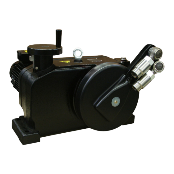
RHD250 to 4000 (Contrac)
Electrical rotary actuator
—
Introduction
RHDE250
RHDE500
Compact actuator for the operation of final
RHDE800
RHDE1250
control elements with preferably 90° rotary
RHDE2500
movement such as valve flaps, ball valves, etc.
RHDE4000
The nominal torque is transferred through a lever
actuator. A special electronic unit controls the
actuator. The special electronic unit serves as the
interface between actuator and control system.
Electrical rotary actuator for the
operation of final control elements.
Additional Information
Additional documentation on RHD250 to 4000
(Contrac) is available for download free of charge at
www.abb.com/actuators.
Alternatively simply scan this code:
Advertisement
Table of Contents

Related Manuals for ABB RHD Series


Summary of Contents for ABB RHD Series
- Page 1 90° rotary (Contrac) is available for download free of charge at RHDE2500 movement such as valve flaps, ball valves, etc. www.abb.com/actuators. RHDE4000 Alternatively simply scan this code: The nominal torque is transferred through a lever actuator. A special electronic unit controls the actuator.
-
Page 2: Table Of Contents
RHD250 to 4000 (Contrac) ELECTRICAL ROTARY ACTUATOR | SEI/RHD250/4000-EN REV. A Table of contents Safety ................3 Fuses ..................24 General information and instructions ........3 Electronic unit for field installation ....... 24 Warnings ..................3 Electronic units for rack installation ......24 Intended use ................ -
Page 3: Safety
RHD250 to 4000 (Contrac) ELECTRICAL ROTARY ACTUATOR | SEI/RHD250/4000-EN REV. A 1 Safety General information and instructions Warnings The warnings in these instructions are structured as follows: These instructions are an important part of the product and must be retained for future reference. DANGER Installation, commissioning, and maintenance of the product may only be performed by trained specialist personnel who have... -
Page 4: Intended Use
/ or theft of data or information. ABB Automation Products GmbH and its affiliates are not liable for damages and / or losses related to such security breaches, any unauthorized access, interference, intrusion, leakage and /... -
Page 5: Introduction
Do not lift or lower the actuator when it is mounted Figure 1: RHD (illustrations may differ from actual installation) on a valve or similar final control element. This service instruction refers to the ABB rotary actuators • Switch-off the voltage supply; make sure that unintentional RHD250 to RHD4000. -
Page 6: Lubrication
RHD250 to 4000 (Contrac) ELECTRICAL ROTARY ACTUATOR | SEI/RHD250/4000-EN REV. A 3 Lubrication Oil change Mounting position The spur gearing of the actuator RHD250 / RHD500 / RHD800 / Note RHD1250 / RHD2500 / RHD4000 (Contrac) are lubricated with Oils for different temperature ranges may not mixed. oil. -
Page 7: Rhd Oil Types
RHD250 to 4000 (Contrac) ELECTRICAL ROTARY ACTUATOR | SEI/RHD250/4000-EN REV. A RHD oil types Ambient temperature Oil types - DIN 51517 Default oil filled with delivery Alternative oil −10 to 65 °C (15 to 150 °F) Castrol Alpha BMP 220 – DIN 51517 ESSO Spartan EP 220 –... -
Page 8: Maintenance
RHD250 to 4000 (Contrac) ELECTRICAL ROTARY ACTUATOR | SEI/RHD250/4000-EN REV. A 4 Maintenance Safety instructions Lever Lever removal WARNING Risk of injury due to live parts! Risk of death or serious injuries due to electricity and unexpected machine movements. In automatic mode the motor is always under power, even at standstill. -
Page 9: Lever Installation
RHD250 to 4000 (Contrac) ELECTRICAL ROTARY ACTUATOR | SEI/RHD250/4000-EN REV. A Lever installation Ball-and-socket-joint NOTICE Make sure that the shaft surface and the shaft bore in the ever are clean and free of grease or any other lubricant. 1. Put the appropriate key into the groove in the shaft. -
Page 10: Tightening Torques And Dimensions Of Lever Screws
RHD250 to 4000 (Contrac) ELECTRICAL ROTARY ACTUATOR | SEI/RHD250/4000-EN REV. A … 4 Maintenance … Lever Note Installation The ball-and-socket joint may be mounted / removed with the 1. Push the bolt of the ball-and-socket joint into the lever hole. lever mounted on the shaft or with dismounted lever. -
Page 11: Sealing Ring Of Output Drive Shaft
RHD250 to 4000 (Contrac) ELECTRICAL ROTARY ACTUATOR | SEI/RHD250/4000-EN REV. A Sealing ring of output drive shaft A Drive pinion D Motor B Output shaft E Brake C Handwheel mechanism Figure 7: Sectional view of PME120 The following general explanations for the sealing ring 13. -
Page 12: Sealing Ring Of Hand Wheel Drive / Hand Wheel Shaft
RHD250 to 4000 (Contrac) ELECTRICAL ROTARY ACTUATOR | SEI/RHD250/4000-EN REV. A … 4 Maintenance Sealing ring of hand wheel drive / hand Sealing of the position sensor drive wheel shaft RHD250...RHD800 1 O-ring 4 Sealing ring 2 Housing flange 5 Screws 3 Flange screws 6 Hand wheel Figure 9: Handwheel... -
Page 13: Rhd1250
RHD250 to 4000 (Contrac) ELECTRICAL ROTARY ACTUATOR | SEI/RHD250/4000-EN REV. A RHD1250... RHD4000 Motor By the time of printing this document Contrac actuators use two basic motor series. Motor type MC..71..MC..100 of the series 1 feature a ‘C’ at the end of the name code, motor type MC..71.. -
Page 14: Motor Removal
RHD250 to 4000 (Contrac) ELECTRICAL ROTARY ACTUATOR | SEI/RHD250/4000-EN REV. A … 4 Maintenance … Motor Motor removal Motor flange O-ring DANGER Danger to life due to unexpected movement of the actuator! Note that the actuator position may be changed accidentally by the external load on the drive when the brake is released, or the motor is removed. -
Page 15: Motor Disassembly / Assembly
RHD250 to 4000 (Contrac) ELECTRICAL ROTARY ACTUATOR | SEI/RHD250/4000-EN REV. A Motor disassembly / assembly Motors without fan on rear shaft end 1 Key 3 Extraction tool 2 Flange screw Figure 16: Removal of the motor flange; example shows motor of series 1 1 Brake cover screw 3 Brake fastening screw 2 Cover... - Page 16 RHD250 to 4000 (Contrac) ELECTRICAL ROTARY ACTUATOR | SEI/RHD250/4000-EN REV. A … 4 Maintenance … Motor Motors with fan on rear shaft end 1 Rear end of motor shaft 2 Brake cover screws 1 Cover 3 Motor 2 Cover screws Figure 20: Undo brake cover Figure 17: Cover removal 4.
- Page 17 RHD250 to 4000 (Contrac) ELECTRICAL ROTARY ACTUATOR | SEI/RHD250/4000-EN REV. A 12. Undo pinion screw ; use appropriate retainer to secure the screw when re-assembling (DELO-ML 5228 or LOCTITE 243; both medium-firm; detachable) 13. Use appropriate removal tool to pull the pinion from the shaft.
-
Page 18: Exchange Of Motor Bearings
RHD250 to 4000 (Contrac) ELECTRICAL ROTARY ACTUATOR | SEI/RHD250/4000-EN REV. A … 4 Maintenance … Motor Exchange of motor shaft sealing ring 1 Retaining ring pliers 2 Front flange Figure 28: A Sealing ring seat with shoulder C Oil 18. Use appropriate retaining ring pliers to remove the bearing retaining ring out of the front flange B sealing ring seat without... -
Page 19: Brake Adjustment
RHD250 to 4000 (Contrac) ELECTRICAL ROTARY ACTUATOR | SEI/RHD250/4000-EN REV. A Brake adjustment Brake of motor series 1 Brake of motor series 2 WARNING WARNING Risk of injury Risk of injury Note that the actuator position may be changed accidentally Note that the actuator position may be changed accidentally by the external load on the drive when the brake is released or by the external load on the drive when the brake is released or... -
Page 20: Electrical Connections
RHD250 to 4000 (Contrac) ELECTRICAL ROTARY ACTUATOR | SEI/RHD250/4000-EN REV. A 5 Electrical connections Covers WARNING Risk of injury due to live parts! Risk of death or serious injuries due to electricity and unexpected machine movements. In automatic mode the motor is always under power, even at standstill. -
Page 21: Electronic Unit Ebn853 (Contrac) / Ebn861 (Contrac) / Ebs862 (Contrac)
RHD250 to 4000 (Contrac) ELECTRICAL ROTARY ACTUATOR | SEI/RHD250/4000-EN REV. A Electronic Unit EBN853 (Contrac) / EBN861 (Contrac) / EBS862 (Contrac) Analog / Digital BE = digital input BA = digital output Figure 36: Control via analog input 0/4 to 20 mA, HART® communication or digital inputs... -
Page 22: Profibus Dp
RHD250 to 4000 (Contrac) ELECTRICAL ROTARY ACTUATOR | SEI/RHD250/4000-EN REV. A … 5 Electrical connections … Electronic Unit EBN853 (Contrac) / EBN861 (Contrac) / EBS862 (Contrac) PROFIBUS DP® BA = digital output Figure 37: Control via fieldbus PROFIBUS DP®... -
Page 23: Electronic Unit Ebn852 (Contrac)
RHD250 to 4000 (Contrac) ELECTRICAL ROTARY ACTUATOR | SEI/RHD250/4000-EN REV. A Electronic Unit EBN852 (Contrac) Analog / Digital BE = digital input BA = digital output Figure 38: Control via analog input 0/4 to 20 mA, HART® communication or digital inputs... -
Page 24: Fuses
RHD250 to 4000 (Contrac) ELECTRICAL ROTARY ACTUATOR | SEI/RHD250/4000-EN REV. A … 5 Electrical connections Fuses Electronic unit for field installation Type Fuse Installation location Rated current of fuse Design at 115 V AC at 230 V AC EBN853 External fuse External 16 A, slow —... -
Page 25: Fuse Location Ebn853
RHD250 to 4000 (Contrac) ELECTRICAL ROTARY ACTUATOR | SEI/RHD250/4000-EN REV. A Fuse location EBN853 Fuse location EBN861 / EBS862 NOTICE Remove the cover of the connection chamber carefully in order to avoid any damage. Figure 41: 1 Tap holes for cable glands 5 Anti-dewing heater fuse 2 Cable gland 6 Terminals (motor cable) -
Page 26: External Fuses For Ebn861 / Ebs862
RHD250 to 4000 (Contrac) ELECTRICAL ROTARY ACTUATOR | SEI/RHD250/4000-EN REV. A … 5 Electrical connections … Fuses External fuses for EBN861 / EBS862 Fuse location in EBS852 One 35 A fuse and the 16 A thermal circuit breaker are supplied together with the electronic unit EBN861 / EBS862. -
Page 27: Exchange Of Position Sensor
RHD250 to 4000 (Contrac) ELECTRICAL ROTARY ACTUATOR | SEI/RHD250/4000-EN REV. A 6 Exchange of position sensor Dismounting 1 Male connector 3 Female connector 1 Fastening screws 3 Shaft gear 2 Plug housing 2 Position sensor 3 Sensor cable Figure 47: Example shows RHD500 (without heater) Figure 49: Mounting position (Example shows RHD500) 1. -
Page 28: Mounting
RHD250 to 4000 (Contrac) ELECTRICAL ROTARY ACTUATOR | SEI/RHD250/4000-EN REV. A … 6 Exchange of position sensor Mounting 1 Tension spring 1 Fastening screws 3 Shaft gear Figure 50: Position sensor 2 Position sensor 3 Sensor cable The toothed gear pair of the position sensor is held in place by a Figure 51: Mounting position (Example shows RHD500) tension spring , to ensure backlashfree motion when the... -
Page 29: Electrical Test Values
RHD250 to 4000 (Contrac) ELECTRICAL ROTARY ACTUATOR | SEI/RHD250/4000-EN REV. A 7 Electrical test values Test values (position sensor) DANGER Danger to life due to unexpected movement of the actuator! Unexpected movement of the actuator may lead to very serious injuries or to death. •... -
Page 30: Test Values (Brake And Motor)
RHD250 to 4000 (Contrac) ELECTRICAL ROTARY ACTUATOR | SEI/RHD250/4000-EN REV. A … 7 Electrical test values Test values (Brake and Motor) Brake voltage DC 135 V with AC 115/AC230 V mains supply. Motor voltage Check for currents symmetry (i. e. with clip-on ammeter). Winding resistance Depending on the actuator version proceed as follows: •... -
Page 31: Troubleshooting
RHD250 to 4000 (Contrac) ELECTRICAL ROTARY ACTUATOR | SEI/RHD250/4000-EN REV. A 8 Troubleshooting 9 Troubleshooting NOTICE LED signals at commissioning and service Check wiring, polarity and all plug and terminal connections field before you start detailed trouble shooting. Provided the electronic unit is supplied with voltage (green LED on LCP ‘ON’), the red LED on the commissioning and service field The following chapter specifies various possible failure events or provide some basic status information:... -
Page 32: General
RHD250 to 4000 (Contrac) ELECTRICAL ROTARY ACTUATOR | SEI/RHD250/4000-EN REV. A … 9 Troubleshooting General Figure 56: General... -
Page 33: Failures At Brake, Fuse Or Wiring
RHD250 to 4000 (Contrac) ELECTRICAL ROTARY ACTUATOR | SEI/RHD250/4000-EN REV. A Failures at brake, fuse or wiring Figure 57: Failures at brake, fuse or wiring... -
Page 34: Operation Mode (Man / Aut)
RHD250 to 4000 (Contrac) ELECTRICAL ROTARY ACTUATOR | SEI/RHD250/4000-EN REV. A … 9 Troubleshooting Operation mode (MAN / AUT) Figure 58: Operation mode (MAN / AUT) -
Page 35: Input Configuration
RHD250 to 4000 (Contrac) ELECTRICAL ROTARY ACTUATOR | SEI/RHD250/4000-EN REV. A Input configuration Figure 59: Input configuration... -
Page 36: Operation Behind Step Controller
RHD250 to 4000 (Contrac) ELECTRICAL ROTARY ACTUATOR | SEI/RHD250/4000-EN REV. A … 9 Troubleshooting Operation behind step controller Figure 60: Operation behind step controller... -
Page 37: Failure Diagram
RHD250 to 4000 (Contrac) ELECTRICAL ROTARY ACTUATOR | SEI/RHD250/4000-EN REV. A Failure Diagram Figure 61: Failure Diagram... -
Page 38: Failure Due To Response Of Positioning Loop Monitoring
RHD250 to 4000 (Contrac) ELECTRICAL ROTARY ACTUATOR | SEI/RHD250/4000-EN REV. A … 9 Troubleshooting Failure due to response of positioning loop monitoring Figure 62: Failure due to response of positioning loop monitoring General Actuator runs with creeping speed in one or both end positions –... -
Page 39: User Interface Menus
RHD250 to 4000 (Contrac) ELECTRICAL ROTARY ACTUATOR | SEI/RHD250/4000-EN REV. A User interface menus Figure 63: Troubleshooting related menus in the user interface (digitally manipulated screen shot) The following table represents the first 2 menu levels (see also User interface menus on page 39) of the graphical user interface as far as the troubleshooting is concerned. - Page 40 We reserve the right to make technical changes or modify the contents of this document without prior notice. With regard to purchase orders, the agreed particulars shall prevail. ABB does not accept any responsibility whatsoever for potential errors or possible lack of information in this document.