Table of Contents
Advertisement
Quick Links
User's Manual
EZ-0009
Development Kit for μPD78F8024, μPD78F8025
Target Device
μPD78F8024
μPD78F8025
ZUD-CD-09-0191 (1/29)
September 16, 2009
Yoshinari Ando, Team Manager
Development Tool Solution Group
Multipurpose Microcomputer Systems Division
Microcomputer Operations Unit
NEC Electronics Corporation
Advertisement
Table of Contents

Related Manuals for NEC EZ-0009


Summary of Contents for NEC EZ-0009
- Page 1 ZUD-CD-09-0191 (1/29) September 16, 2009 Yoshinari Ando, Team Manager Development Tool Solution Group Multipurpose Microcomputer Systems Division Microcomputer Operations Unit NEC Electronics Corporation User’s Manual EZ-0009 Development Kit for μPD78F8024, μPD78F8025 Target Device μPD78F8024 μPD78F8025...
- Page 2 NEC Electronics does not assume any liability for infringement of patents, copyrights or other intellectual property rights of third parties by or arising from the use of NEC Electronics products listed in this document or any other liability arising from the use of such products. No license, express, implied or otherwise, is granted under any patents, copyrights or other intellectual property rights of NEC Electronics or others.
- Page 3 ZUD-CD-09-0191 3/29 Safety Precautions This document explains matters to be noted for safe use of EZ-0009. Be sure to read this before using EZ-0009. Symbols Used This document uses the following symbols for matters to be observed for the safe use of the unit.
- Page 4 EZ-0009 User’s Manual ZUD-CD-09-0191 4/29 Warnings Warnings Do not drop or jolt the unit. Doing so may break or damage the unit, causing fire or electric shock. Do not disassemble or modify the unit. Doing so may cause product failure, emission of smoke, fire, or electric shock.
- Page 5 - Environments where static electricity or electrical noise is readily generated. Such influences can lead to electric shock or product failure. If a liquid enters the unit, cut the power supply, and consult your dealer or NEC Electronics sales representative.
-
Page 6: Table Of Contents
CHAPTER2 NAMES AND FUNCTIONS OF HARDWARE................11 2.1 Names of Supplied Hardware........................11 2.2 Part Names and Functions of Simple On-chip debug emulator (EZ-0009-Emulator) ..12 2.3 Part Names and Functions of Target Board (QB-78F8025-TB) ..........13 CHAPTER3 HOW TO USE ..............................15 3.1 Target System Design............................. -
Page 7: Introduction
ZUD-CD-09-0191 7/29 INTRODUCTION μPD78F8024, μPD78F8025 Development Kit (EZ-0009) is the kit which can develop application system by using uPD78F8024, uPD78F8025 microcontrollers. By installing software development tools and USB driver software to PC, and by connecting USB cable, total development flow can be realized. - Page 8 The readers of this manual are assumed to be familiar with the device functions and usage of uPD78F8024, uPD78F8025, and to have knowledge of debuggers and flash programming. Purpose This manual is intended to give users an understanding of the basic specifications and correct use of EZ-0009.
-
Page 9: Chapter1 Overview
Flash memory programming Flash memory programming is possible by this development kit. USB connection Simple On-chip debug emulator (EZ-0009-Emulator) can be connected to the host PC via USB interface 2.0 or 1.1. 1.2 Supported Devices uPD78F8024 and uPD78F8025... -
Page 10: Hardware Specifications
Humidity : 10 to 80% RH ‘(no condensation) External dimensions 55 x 71 x 1.5 mm Weight Approximately 16 g Note In case power supply to target system is used from EZ-0009-Emulator, current supply capacity have to be 500mA. -
Page 11: Chapter2 Names And Functions Of Hardware
The part names described in this chapter are used throughout this document. This chapter provides an overview of the various functions. Reading it through, the reader will gain a basic of EZ-0009. While reading this chapter, also check if the hardware has a defect. 2.1 Names of Supplied Hardware Figure 2-1 shows the names of hardware supplied with EZ-0009. -
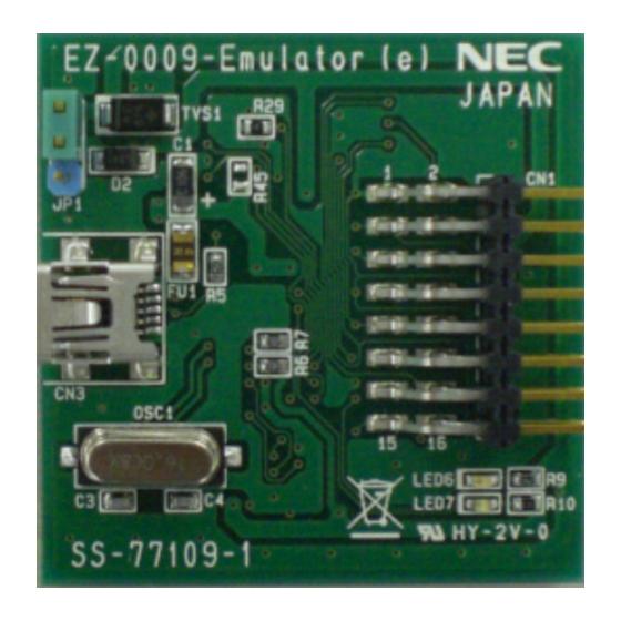
Page 12: Part Names And Functions Of Simple On-Chip Debug Emulator (Ez-0009-Emulator)
Power supply of the target system is used. 2-3pin short (2) USB Interface connector (CN3) This is a connector used to connect EZ-0009-Emulator with the host machine, via a USB cable. (3) Target interface connector (CN1) This is a connector used to connect EZ-0009-Emulator with the target system, via a 16-pin target cable. -
Page 13: Part Names And Functions Of Target Board (Qb-78F8025-Tb)
For their functions, refer to (1) to (6) below. Figure 2-3 Part Names of Target board (QB-78F8025-TB) (1) On-chip debug interface connector (CN3) This is a connector used to connect QB-78F8025-TB with EZ-0009-Emulator, via a 16-pin target cable. (2) Peripheral board connector (CN1/CN2) These are connectors for external board connection (2.54mm pitch). - Page 14 EZ-0009 User’s Manual ZUD-CD-09-0191 14/29 (5) Resonator (OSC1) This board is using 8MHz ceramic resonator for main clock of uPD78F8025. Need to connect 8MHz resonator as main clock when on-chip debug is used. (6) Power LED (LED1) This LED (Red) is turned on when power is supplied.
-
Page 15: Chapter3 How To Use
ZUD-CD-09-0191 15/29 Chapter3 How to Use This chapter describes how to use EZ-0009 when performing on-chip debugging and flash programming. To perform on-chip debugging for uPD78F8025 microcontroller, a specific program (debug function) must be downloaded to the microcontroller, and then debug the microcontroller mounted on the target system. -
Page 16: Pin Assignment
EZ-0009 User’s Manual ZUD-CD-09-0191 16/29 3.1.1 Pin assignment This section describes the interface signals used between EZ-0009-Emulator and the target system. Table 3-1 describes the pin assignment. Table 3-2 describes the functions of each pin. Table 3-1 Pin Assignment Pin Name Pin Name R.F.U. -
Page 17: Circuit Connection Example
EZ-0009 User’s Manual ZUD-CD-09-0191 17/29 3.1.2 Circuit connection example Figure 3-2 shows circuit connection example. Note The value described in the circuit connection example is reference value. Figure 3-2 Circuit Connection Example uPD78F8024,uPD78F8025 Target Connector Note3 3K~10KΩ RESET RESET_OUT Note1... -
Page 18: Simple On-Chip Debugging
18/29 3.2 Simple On-chip debugging This section describes the system configuration, startup procedure for debugging when simple on-chip debugging is performed with EZ-0009-Emulator. 3.2.1 Debug functions Table 3-3 lists the debug functions of this development kit. Table 3-3 Debug Functions... -
Page 19: Software Installation
Download driver from following URL. http://www.necel.com/micro/en/solution/lighting/download.html When connecting EZ-0009-Emulator to PC by using USB cable, “Found New Hardware Wizard” dialog box is displayed. Select “Yes, now and every time I connect a device”, and click [Next]. Select “Install from a list or specific location (Advanced)”, and click [Next]. -
Page 20: Securing Of User Resource
EZ-0009 User’s Manual ZUD-CD-09-0191 20/29 3.2.3 Securing of user resource The user must prepare the following to perform communication between EZ-0009-Emulator and uPD78F8024, uPD78F8025 and implement each debug function. Secure of memory space The shaded portions in Figure 3-3 are the areas reserved for placing the debug monitor program, so user program cannot be allocated in these spaces. - Page 21 EZ-0009 User’s Manual ZUD-CD-09-0191 21/29 (a) Debug monitor area This area must be secured for placing the debug monitor program. In case this area is re-programmed by self-programming, on-chip debug function will not work. This area must be filled with 0xFF.
- Page 22 EZ-0009 User’s Manual ZUD-CD-09-0191 22/29 (c) Software break area This area is used for software break. This area must be filled with 0xFF. Assemble source example ------------------------------------------------------------------------------- SS4 CSEG AT 07EH ;”SS4” is an arbitrary symbol name (eight characters or less)
-
Page 23: System Startup Procedure
Observe the following order. (1) Jumper setting Set the power select jumper (JP1) of EZ-0009-Emulator by referring to table 3-4. Caution Do not change the jumper setting while the USB cable is connected. Table3-4 Setting of Power Select Jumper (JP1) - Page 24 For the operation after this step, refer to the user’s manual for the debugger (ID78K0-QB). If the debugger does not start normally or the operation is unstable, the possible causes may be the following. ・ Communication error between EZ-0009-Emulator and target system ・ The user resource has not been secured ・...
-
Page 25: Caution On Debugging
EZ-0009 User’s Manual ZUD-CD-09-0191 25/29 3.2.5 Caution on debugging (1) Use external 8MHz oscillator as main system clock for debugging. (2) Forced break cannot be used during following status is kept. When forced break is executed, “monitor timeout error*” will occur. - Page 26 EZ-0009 User’s Manual ZUD-CD-09-0191 26/29 (6) RRM (Real-time RAM monitor) and DMM (Dynamic Memory Modification) cannot be used. Setting itself by ID78K0-QB-MON-HCD is possible, but “monitor timeout error*” will occur. When RRM or DMM is set on ID78K0-QB-MON-HCD, debugger will hang up.
-
Page 27: Simple Flash Programming
This section describes the system startup procedure when executing flash memory programming to uPD78F8024, uPD78F8025 by using EZ-0009-Emulator. Observe the following order. Use this simple flash programming function by using EZ-0009-Emulator only for evaluation in your system development. 3.3.1 Software Installation This section describes software installation which is need for simple flash programming. -
Page 28: Flash Programming Procedure
This section describes the flash programming procedure. Observe the following order. (1) Jumper setting Set the power select jumper (JP1) of EZ-0009-Emulator by referring to table 3-5. Caution Do not change the jumper setting while the USB cable is connected. Table3-5 Setting of Power Select Jumper... - Page 29 EZ-0009 User’s Manual ZUD-CD-09-0191 29/29 (4) Applying power to target system Turn on power to the target system. In case Power select jumper is set to “1-2pin short”: provide Vin power supply In case Power select jumper is set to “2-3pin short”: provide Vin,V power supply (5)...