Table of Contents
Advertisement
Quick Links
—
A B B M E A S U R E M E N T A N D A N A LY T I C S | O P E R AT I N G I N S T R U C T I O N
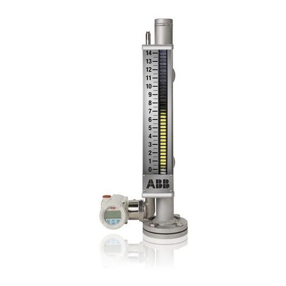
KM26
Magnetic level gauges
Introduction
—
Magnetic level gauges
With over 350,000 installations worldwide, the
KM26 magnetic level gauge has provided custom
engineered solutions to liquid level applications in
industries such as: oil and gas, refinery, chemical,
petrochemical, power generation and many more.
The KM26 MLG has proven itself to be a safe,
reliable, maintenance free solution for total and / or
interface level detection in toxic, corrosive, high
pressure and high temperature processes.
ABB offers the standard KM26 magnetic level gauge
with a chamber of virtually any non-magnetic
material, extruded process connections, a custom
engineered float and all accessories with 316
stainless steel construction.
Magnetic level gauge, MagWave
dual chamber level system and
external chamber
Innovative magnetic
level gauge solutions
ABB also offers a dual chamber redundant level
system, which has a proven record of improving
feedwater heater reliability in power plants around
the world. The MagWave combines a highly visible
magnetic level indicator with the precise level
measurement of a guided wave radar transmitter.
Redundant level control can be achieved by adding a
magnetostrictive transmitter or switch to the float
chamber.
Advertisement
Table of Contents

Related Manuals for ABB KM26


Summary of Contents for ABB KM26
- Page 1 The MagWave combines a highly visible petrochemical, power generation and many more. magnetic level indicator with the precise level The KM26 MLG has proven itself to be a safe, measurement of a guided wave radar transmitter. reliable, maintenance free solution for total and / or...
-
Page 2: Table Of Contents
KM26 | M AGN ETI C L EV EL G AU GE | O I/KM 26 -E N REV I Contents Introduction . . . . . . . . . . . . . . . . . . . . . . . . . . . . . . . .2 Safety . - Page 3 KM26 | M AG N ET I C LE V EL G AUG E | O I/KM 2 6 -EN RE V I Introduction This manual is designed to provide information on installing, magnetic coupling between the float and the indicator. The...
-
Page 4: Safety
KM26 | M AGN ETI C L EV EL G AU GE | O I/KM 26 -E N REV I Safety CAUTION General safety information Only qualified and authorized personnel are to be tasked The following safety section provides an overview of the... - Page 5 KM26 | M AG N ET I C LE V EL G AUG E | O I/KM 2 6 -EN RE V I . . . 2 Safety • the maximum process temperature must not be Qualified personnel exceeded. Installing, commissioning and maintaining the MLG system •...
- Page 6 KM26 | M AGN ETI C L EV EL G AU GE | O I/KM 26 -E N REV I . . . 2 Safety CAUTION Safety information for electrical installation • for category II 1 G installation, parts of the equipment...
- Page 7 KM26 | M AG N ET I C LE V EL G AUG E | O I/KM 2 6 -EN RE V I . . . 2 Safety Certifications nameplates refer to the respective datasheets of the transmitters, switches and accessories to have the details of the IP The MLG is identified by the name plates.
- Page 8 KM26 | M AGN ETI C L EV EL G AU GE | O I/KM 26 -E N REV I . . . 2 Safety Temperature classification Temperature classifications of the ATEX approved KM26 is limited to process temperatures up to 50C below the maximum surface temperature allowed for each of the temperature classes as per the below table.
-
Page 9: Mounting
KM26 | M AG N ET I C LE V EL G AUG E | O I/KM 2 6 -EN RE V I . . . 2 Safety Note Hazardous area considerations Unpack the instrument carefully. Inspect all units for damage. - Page 10 KM26 | M AGN ETI C L EV EL G AU GE | O I/KM 26 -E N REV I . . . 3 Mounting MLG configurations not have side connection access. In its simplest form, a top mount consists of a chamber with a single flange at the There are several configurations for the KM26.
- Page 11 KM26 | M AG N ET I C LE V EL G AUG E | O I/KM 2 6 -EN RE V I . . . 3 Mounting Floats Float Stop Springs The float is a strong capsule that is engineered for the...
- Page 12 KM26 | M AGN ETI C L EV EL G AU GE | O I/KM 26 -E N REV I . . . 3 Mounting mounted on the bottom flange for the KM26S and a float stop CAUTION tube for the KM26T. Therefore, as long as the float and the shuttle are magnetically coupled, the shuttle will be visible.
- Page 13 KM26 | M AG N ET I C LE V EL G AUG E | O I/KM 2 6 -EN RE V I . . . 3 Mounting Limit switches Limit switch use To signal specific liquid levels, the KM26 can be equipped with The MLG switch will provide either a normally open or several different types of ABB limit switches.
- Page 14 KM26 | M AGN ETI C L EV EL G AU GE | O I/KM 26 -E N REV I . . . 3 Mounting General installation guidelines For high temperature applications using insulation jackets and alternate rod mounting approach is used (figure 15).
- Page 15 KM26 | M AG N ET I C LE V EL G AUG E | O I/KM 2 6 -EN RE V I . . . 3 Mounting Note Insulation jacket pads are intended to wrap only the KM26 chamber, not the limit switches themselves. Refer to figure 17 and table 3.
- Page 16 KM26 | M AGN ETI C L EV EL G AU GE | O I/KM 26 -E N REV I . . . 3 Mounting Magnetostrictive transmitter installation identify the ‘factory zero mark’ sticker on the sensor tube of the transmitter.
- Page 17 KM26 | M AG N ET I C LE V EL G AUG E | O I/KM 2 6 -EN RE V I . . . 3 Mounting mounting tabs of the transmitter match up to the The transmitter mounting tabs will hold the insulation chamber.
- Page 18 KM26 | M AGN ETI C L EV EL G AU GE | O I/KM 26 -E N REV I . . . 3 Mounting Isolation valves Insulation Valves should be installed between the tank and the KM26 for Chamber, switch, transmitter, and flange insulations are maintenance purposes and are available as an option.
- Page 19 KM26 | M AG N ET I C LE V EL G AUG E | O I/KM 2 6 -EN RE V I . . . 3 Mounting is typically at 6 o’clock. Openings for the connections are Insulation instructions...
- Page 20 KM26 | M AGN ETI C L EV EL G AU GE | O I/KM 26 -E N REV I . . . 3 Mounting Oversize chamber with guide rods Cryogenic insulation CAUTION In applications where flashing is a concern (rapid change from liquid to gas;...
-
Page 21: Troubleshooting
KM26 | M AG N ET I C LE V EL G AUG E | O I/KM 2 6 -EN RE V I Troubleshooting Indicator decoupling • magnetic particles in the process fluid have become attached to the float changing its buoyancy. Install... - Page 22 KM26 | M AGN ETI C L EV EL G AU GE | O I/KM 26 -E N REV I . . . 5 Service and maintenance Equipment and tools Removing an MLG from service • open-end wrenches or an adjustable wrench to fit the Close the BOTTOM process isolation valve to prevent further process studs / nuts.
- Page 23 KM26 | M AG N ET I C LE V EL G AUG E | O I/KM 2 6 -EN RE V I . . . 5 Service and maintenance MLG replacement / spare parts KM26 magnetic bargraph glass installation procedure (refer to figures 29...
- Page 24 KM26 | M AGN ETI C L EV EL G AU GE | O I/KM 26 -E N REV I . . . 5 Service and maintenance KM26 shuttle replacement glass installation procedure Figure 27 - KM26 shuttle replacement glass installation procedure...
- Page 25 KM26 | M AG N ET I C LE V EL G AUG E | O I/KM 2 6 -EN RE V I . . . 5 Service and maintenance KM26 shuttle replacement glass 4 Carefully align replacement glass with shuttle indicator installation procedure into scale channel and lower into bottom tube holder.
- Page 26 KM26 | M AGN ETI C L EV EL G AU GE | O I/KM 26 -E N REV I . . . 5 Service and maintenance KM26 bargraph replacement glass installation procedure Figure 29 - KM26 bargraph replacement glass installation procedure...
- Page 27 KM26 | M AG N ET I C LE V EL G AUG E | O I/KM 2 6 -EN RE V I . . . 5 Service and Maintenance KM26 bargraph replacement glass should register with corresponding flat faces in cavity of installation procedure bottom tube holder.
-
Page 28: Mlg Parts
KM26 | M AGN ETI C L EV EL G AU GE | O I/KM 26 -E N REV I MLG parts KM26S parts breakdown drawing Item Description Part # Scale assembly (includes 1-ABC) Ser. # - 1 Tube with follower Ser. - Page 29 KM26 | M AG N ET I C LE V EL G AUG E | O I/KM 2 6 -EN RE V I . . . 6 MLG parts KM26T parts breakdown drawing Item Description Part # Scale assembly (includes 1-ABC) Ser.
-
Page 30: Mlg Parts Ordering
KM26 | M AGN ETI C L EV EL G AU GE | O I/KM 26 -E N REV I MLG parts ordering ABB can provide custom fit insulation for most installations. Note Contact the factory for details. Each KM26 is built to the Floats are subject to change with customer requirements and customer’s specifications, which makes parts for these units... -
Page 31: Warranty
KM26 | M AG N ET I C LE V EL G AUG E | O I/KM 2 6 -EN RE V I Warranty Warranty statement 5 YEAR WARRANTY FOR: If a product is believed to be defective, the original purchaser KM26 magnetic liquid level gauges;... -
Page 32: Rma Form
Be sure to include the Return Authorization (RA) number on the shipping label or package to the attention: Customer Ser- vice. A copy of this document should also be included with the packing list. ABB wants to maintain a safe work environment for its employees. - Page 33 KM26 | M AG N ET I C LE V EL G AUG E | O I/KM 2 6 -EN RE V I...
- Page 34 KM26 | M AGN ETI C L EV EL G AU GE | O I/KM 26 -E N REV I...
- Page 35 KM26 | M AG N ET I C LE V EL G AUG E | O I/KM 2 6 -EN RE V I...
- Page 36 We reserve the right to make technical changes or modify the contents of this document without prior notice. With regard to purchase orders, the agreed particulars shall prevail. ABB does not accept any responsibility whatsoever for potential errors or possible lack of information in this document.