
Related Manuals for ABB DCGear


Summary of Contents for ABB DCGear
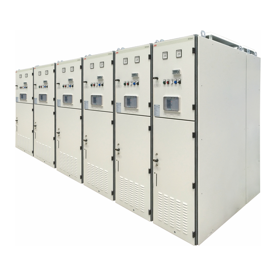
- Page 1 — PRODUCT MANUAL DCGear • High active and passive safety • Internal arc proof 50 kA 250 ms • High availability and low maintenance...
-
Page 3: Table Of Contents
— Table of contents 004 – 005 General information 006 – 007 Receiving, handling and storage 008 – 015 Installation 016 – 022 Technical characteristics Preliminary checks and controls Commissioning 025 – 030 Maintenance Recordings 031 – 034 Accessories and spare parts... -
Page 4: General Information
1.1 Introduction and safety In addition to the specific procedures described 1.1.1 Introduction in this manual during the installation and The paintings DCGear have been designed to maintenance, always apply the following be compliant with IEC, EN and GB standards. precautions: The correct application and proper operation •... - Page 5 • To avoid risk of electric shock and impact with the mechanical parts moving at high ABB can provide an adequate service to support all the activities of installation, use and speed, this equipment must be installed, operated and maintained by qualified maintenance of equipment.
-
Page 6: Receiving, Handling And Storage
ABB sales office about the damage occurred before installation. in transit. Keep the damaged material for the carrier's inspection. - Page 7 R E C E I V I N G , H A N D L I N G A N D S T O R A G E The handling and lifting DCGear panel, after 2.4.1 Environmental conditions of storage 2.4.1.1 Storage in original packaging...
-
Page 8: Installation
D C G e a r P R O D U C T M A N U A L — 3 Installation — 3.1 Panel size Must be provided enough space even in the back Fig.3.1 – Sizes and In Table 1 are indicated dimensions and weights of the panel, necessary for the opening of the clearances of the compartments in the various types of... - Page 9 I N S T A L L A T I O N 3.2 Foundation and fixing In general can be provided: Warning • Tunnel for the cables for the auxiliary circuits, Heavy duty command and control, in the front of each They can cause death, serious bodily compartment injury or property damage.
- Page 10 D C G e a r P R O D U C T M A N U A L — Fig.3.2 - Fixing detail — Fig.3.2...
- Page 11 I N S T A L L A T I O N 3.3 Coupling of the section of electrical panel • Connect adjacent sections inserting the screws Danger M8 supplied in the holes drilled on the side of High voltage each compartment.
- Page 12 D C G e a r P R O D U C T M A N U A L — Fig. 3.3a - Compartment coupling Bolt M8 Junction uninsulated — Fig.3.3a...
- Page 13 I N S T A L L A T I O N — Fig. 3.3b - Compartment coupling coupling bars detail Screw head — Fig.3.3b...
- Page 14 3.4.1 General criteria (lighting, etc.) The equipment and components used in the Signals from instrument transformers of DCGear panels are designed, manufactured and current or voltage (TA-TV) or current shunts assembled with specific criteria and measures, (shunt) intended for instruments analog gauges to ensure the immunity of low-level circuits against Power circuits >200 Vdc and 300 Vac...
- Page 15 I N S T A L L A T I O N 3.4.2 Main power circuit connections After the header proceed to connecting cables DANGER to the bar, making sure not to decrease in any The voltages present in the equipment way the insulation distances.
-
Page 16: Technical Characteristics
4.1 General information 4.1.1 Switchgear description All the metallic parts will be connected to the earth The proposed DCGear are equipment with metal collector. The metallic parts of the withdrawable enclosure metal-clad type, for indoor, a internal equipment remain connected to the earth also in arc proof and comply with norms GB/T 25890, the test, disconnected and between each position. - Page 17 T E C H N I C A L C H A R A C T E R I S T I C S 4.2 Main electrical characteristics 4.3 Environmental condition The main electrical characteristics of the DC section The environmental conditions, refer to the are the follows: micro environment in which equipment is •...
- Page 18 D C G e a r P R O D U C T M A N U A L 4.6.1 HSCB Compartment As above two drawings show:when the HSCB is in different positions of service,test and disconnected, the indicator will pointing to different directions.
- Page 19 T E C H N I C A L C H A R A C T E R I S T I C S The Operation Lever How to implement: The left picture shows that the trolley which is in test position is locked and the HSCB is allowed to be closed.When the trolley reachs the position, it is needed to move the lever to the direction of which the picture shows before closing the...
- Page 20 D C G e a r P R O D U C T M A N U A L The lower locker is used to lock the service position as be showed in picture above, rotating the key will cause the latch to be plugged into the notch on the cam to lock the route.
- Page 21 T E C H N I C A L C H A R A C T E R I S T I C S 4.6.2 Low voltage compartment 4.6.3 Rear bus-bar compartment This compartment contains the logic module of This compartment contains the main and the cable MS protection and control relay, the low voltage connections busbars.
- Page 22 D C G e a r P R O D U C T M A N U A L 4.7 HSCB cubicle available configurations Main busbar Main busbar Main busbar Gpro Gpro Gpro Feeder Rectifier Feeder with Line DS Main busbar Main busbar Main busbar By-pass busbar...
-
Page 23: Preliminary Checks And Controls
P R E L I M I N A R Y C H E C K S A N D C O N T R O L S — 5 Preliminary checks and controls CAUTION • Check that the power bus bars and power After installing the panel and after the cable connections are clean connection of auxiliary circuits, but before... -
Page 24: Commissioning
D C G e a r P R O D U C T M A N U A L — 6 Commissioning DANGER • All trolley are in the isolated position, with the High voltage auxiliary circuits connected properly The voltages present in the equipment •... -
Page 25: Maintenance
Preliminary operation. ATTENTION Before accessing any part of the panel DCGear, Before every operation on power circuits pay attention scrupulously respecting access ensure that the main circuit is properly procedures defined for each compartment. - Page 26 D C G e a r P R O D U C T M A N U A L General clean and greasing Activity: Clean and remove any dirt from the inside of each compartment, debris, deposits, etc. Clean the insulating parts, the bars and insulators of high voltage cell, in the bus bar compartment and the connection cables cell.
- Page 27 M A I N T E N A N C E Check and greasing mechanical parts Activity: Make sure that all components bolted are tightened, particularly check the bolts of reactance connection and general of the bus bar, for the torque vale refer to Table 2.
- Page 28 D C G e a r P R O D U C T M A N U A L Check the interlock Activity: Verify the correct operation of the interlocks of rectifier trolley. Put the rectifier trolley in position disconnected, try to remove it from the cell without lifting the locking pin to check that this is in grip.
- Page 29 M A I N T E N A N C E Check auxiliary circuits and protection relays Activity: WARNING Possible tripping protection. Before making this operation make sure that the control system of pts being in safety position. The auxiliary circuits of command and control, such as relays, auxiliary switches, buttons, lamps, etc., generally do not require maintenance, but only regular checking of their functionality.
- Page 30 D C G e a r P R O D U C T M A N U A L 7.2 Corrective maintenance If damaged will be eventually in their turn The corrective maintenance of the panel is to subjected to corrective maintenance and repair, disassembly of components and/or equipment with the replacement of worn or damaged parts, damaged or worn parts and replacing them...
-
Page 31: Recordings
R E C O R D I N G S / A C C E S S O R I E S A N D S P A R E P A R T — 8 Recordings For each panel should establish a register on WARNING which dates back to maintenance, the results When working on fixed parts inside, make... - Page 32 D C G e a r P R O D U C T M A N U A L 9.2 Common spare parts table N° Description Identification Weight (kg) Total quantity Recommended for PTS quantity % Rectifier trolley 62291521B01 Rectifier Diode AR747LT RC + FUSE...
- Page 33 A C C E S S O R I E S A N D S P A R E P A R T N° Description Identification Weight (kg) Total quantity Recommended for PTS quantity % Discrete output module M340 - BMXDDO1602 16 OUTPUTS - SOLID Processor module M340 - MAX...
- Page 34 D C G e a r P R O D U C T M A N U A L N° Description Identification Weight (kg) Total quantity Recommended for PTS quantity % Rele’ with clamp base 24 VDC - 2966676 SSR 3-33 V 3 A (PLC-OSC- 24DC/ 24DC/2/ACT) Command group 105CI...
- Page 36 Phone: +41 58 586 22 11 Fax: +41 58 586 23 05 Email: info.abbsecheron@ch.abb.com ABB China Customer Service Hot Line TEL: 800-820-9696 / 400-820-9696 mail: cn-ep-hotline@abb.com www.abb.com © Copyright 2018 ABB. All rights reserved. Specifications subject to change without notice.