Table of Contents
Advertisement
Advertisement
Table of Contents

Related Manuals for ABB IRB 2400/10


Summary of Contents for ABB IRB 2400/10
- Page 1 Product specification Articulated robot IRB 2400/10 IRB 2400/16 IRB 2400/L M2004...
- Page 3 Product specification Articulated robot 3HAC9112-1 Rev. N IRB 2400/10 IRB 2400/16 IRB 2400/L M2004...
- Page 4 Except as may be expressly stated anywhere in this manual, nothing herein shall be construed as any kind of guarantee or warranty by ABB for losses, damages to persons or property, fit- ness for a specific purpose or the like.
-
Page 5: Table Of Contents
Table of Contents Overview 1 Description 1.1 Structure ............... . .7 1.1.1 Introduction . - Page 6 Table of Contents Rev.N 3HAC 9112-1...
- Page 7 Overview Overview About this Product specification It describes the performance of the manipulator or a complete family of manipulators in terms of: • The structure and dimensional prints • The fulfilment of standards, safety and operating requirements • The load diagrams, mounting of extra equipment, the motion and the robot reach •...
- Page 8 Overview Complementary Product specifications Product Description specification Controller IRC5 with FlexPendant, 3HAC021785-001 Controller Software RobotWare 5.11, 3HAC022349-001 IRC5 Robot User Documen- IRC5 and M2004, 3HAC024534-001 tation Rev.N 3HAC 9112-1...
-
Page 9: Description
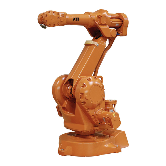
1 Description 1.1.1 Introduction 1 Description 1.1 Structure 1.1.1 Introduction General IRB 2400 is a 6-axis industrial robot, designed specifically for manufacturing industries that use flexible robot-based automation. The robot has an open structure that is specially adapted for flexible use, and can communicate extensively with external systems. - Page 10 1 Description 1.1.1 Introduction Manipulator axes Figure 1 The IRB 2400 manipulator has 6 axes. Rev.N 3HAC 9112-1...
-
Page 11: Different Robot Versions
1.1.2 Different robot versions 1.1.2 Different robot versions General The IRB 2400 is available in three versions and all versions can be mounted inverted. IRB 2400/10 can also be wall mounted. Robot type Handling capacity (kg) Reach (m) IRB 2400/10 10 kg 1.55 m... - Page 12 1 Description 1.1.2 Different robot versions Power consumption Path E1-E2-E3-E4 in the ISO Cube, maximum load. Speed [mm/s] Power consumption [kW] Max. 0.61 - 0.67 1000 0.46 - 0.50 0.40 - 0.44 0.37 - 0.39 Figure 2 Path E1-E2-E3-E4 in the ISO Cube, maximum load. Rev.N 3HAC 9112-1...
- Page 13 1 Description 1.1.2 Different robot versions Dimensions for IRB 2400/L Figure 3 View of the manipulator from the side, rear and above (dimensions in mm). 3HAC 9112-1 Rev.N...
- Page 14 1 Description 1.1.2 Different robot versions Dimensions for IRB 2400/10 and IRB 2400/16 Figure 4 View of the manipulator from the side, rear and above (dimensions in mm). Rev.N 3HAC 9112-1...
-
Page 15: Safety/Standards
1 Description 1.2.1 Standards 1.2 Safety/Standards 1.2.1 Standards The robot conforms to the following standards: EN-Standards Description EN ISO 12100-1 Safety of machinery, terminology EN ISO 12100-2 Safety of machinery, technical specifications EN 954-1 Safety of machinery, safety related parts of control systems EN 60204 Electrical equipment of industrial machines EN ISO 60204-1:2006... - Page 16 1 Description 1.2.1 Standards The robot complies fully with the health and safety standards specified in the EEC’s Machinery Directives. Safety function Description The Service The service information system gathers information about the Information System robot’s usage and determines how hard the robot is used. The (SIS) usage is characterized by the speed, the rotation angles and the load of every axis.
- Page 17 1 Description 1.2.1 Standards The Active Safety Description System The Self Tuning The Process Robot Generation is designed to run at different load Performance (STP) configurations, many of which occur within the same program and cycle. The robot’s installed electrical power can thus be exploited to lift heavy loads, create a high axis force or accelerate quickly without changing the configuration of the robot.
- Page 18 1 Description 1.2.1 Standards The Passive Safety Description System Electronic Position EPS offers axes position status signals, fulfilling applicable Switches (EPS) on up regulations for personnel safety. Five outputs can each be to 7 axes (option) configured to reflect the position of a single axis or a combination of axes.
-
Page 19: Installation
1 Description 1.3.1 Introduction 1.3 Installation 1.3.1 Introduction General The same version of the robot can either be mounted on the floor or inverted. An end effector, max. weight 7, 10 or 16 kg including payload, can be mounted on the robot’s mounting flange (axis 6) depending on the robot version. -
Page 20: Operating Requirements
1 Description 1.3.2 Operating requirements 1.3.2 Operating requirements Protection standards Robot Version/Protection Standard Protection standard IEC529 Standard and Clean Room Manipulator IP54 IRB 2400F/L and C/L Manipulator IP55 Wrist IP67 Connectors IP67 IRB 2400F/10, F/16 IP67, Steam washable Manipulator Clean room standards US Federal Standard 209 Class 100 ISO 14644-1... -
Page 21: Mounting The Manipulator
Torque xy ± 3000 Nm ± 3400 Nm Torque z ± 450 Nm ± 900 Nm IRB 2400/10 and IRB 2400/16 Endurance load in operation Max. load at emergency stop Force xy ± 2000 N ± 2600 N Force z floor + 4100 ±... - Page 22 1 Description 1.3.3 Mounting the manipulator Figure 5 Directions of forces. Note regarding M and F The bending torque (M ) can occur in any direction in the XY-plane of the base coordinate system. The same applies to the transverse force (F Rev.N 3HAC 9112-1...
- Page 23 1 Description 1.3.3 Mounting the manipulator Figure 6 Hole configuration (dimensions in mm). Description Z = center line axis 1 The same dimensions View from the bottom of the base 3HAC 9112-1 Rev.N...
-
Page 24: Load Diagrams
1 Description 1.4.1 Introduction 1.4 Load diagrams 1.4.1 Introduction It is very important to always define correct actual load data and correct payload of the robot. Incorrect definitions of load data can result in overloading of the robot. If incorrect load data and/or loads outside load diagram is used the following parts can be damaged due to overload: •... -
Page 25: Diagrams
1 Description 1.4.2 Diagrams 1.4.2 Diagrams IRB 2400/L Figure 7 Maximum weight permitted for load mounting on the mounting flange at different positions (cen- ter of gravity). Description See the above diagram and the coordinate system in the Product specification - IRC5 with FlexPendant Distance in X -Y plane from Z - axis to the center of gravity ≤... - Page 26 1 Description 1.4.2 Diagrams IRB 2400/10 Figure 8 Maximum weight permitted for load mounting on the mounting flange at different positions (cen- ter of gravity). Description See the above diagram and the coordinate system in the Product specification - IRC5 with FlexPendant Distance in X -Y plane from Z - axis to the center of gravity ≤...
- Page 27 1 Description 1.4.2 Diagrams IRB 2400/16 Figure 9 Maximum weight permitted for load mounting on the mounting flange at different positions (cen- ter of gravity). Description See the above diagram and the coordinate system in the Product specification - IRC5 with FlexPendant Distance in X -Y plane from Z - axis to the center of gravity ≤...
- Page 28 1 Description 1.4.2 Diagrams IRB 2400/16 Extended load diagram Below is an extended load diagram for IRB 2400/16, payload 20 kg. No extra load on wrist, see Figure 14. Figure 10 Maximum weight permitted for load mounting on the mounting flange at different positions (center of gravity).
-
Page 29: Maximum Load And Moment Of Inertia For Full Axis 5 Movement
≤ IRB 2400L = Mass x L 0.31 kgm Axis Robot Type Maximum momemt of inertia ≤ IRB 2400/10 = Mass x ((Z + 0.085) ) + max (J 1.15 kgm ≤ IRB 2400/10 = Mass x L 0.70 kgm... -
Page 30: Wrist Torque
Also arm loads will influence the per- mitted load diagram. For finding the absolute limits of the load diagram, please contact your local ABB organization Max wrist torque Max wrist torque... -
Page 31: Mounting Equipment
1 Description 1.4.4 Wrist torque 1.5 Mounting equipment The robot is supplied with tapped holes on the upper arm and on the base for mounting extra equipment. IRB 2400/L M5 (2x) Depth 9 Max. 10kg 70 (2x) M8 (2x) Depth 14 D - D Max. - Page 32 1 Description 1.4.4 Wrist torque IRB 2400/10 and IRB 2400/16 M6 (2x) M8 (3x) Depth of thread 14 M5 (2x) D=240 Max. 2kg A - A Max. 10kg M8 (3x) R=92 Depth 16 B - B M8 (3x) R=77 Max. 35 kg total...
- Page 33 1 Description 1.4.4 Wrist torque IRB 2400/16 with payload 20 kg M8 (3x) Depth of thread 14 A - A Max. 10kg M8 (3x) R=92 Depth 16 B - B M8 (3x) R=77 Max. 35 kg total Depth 16 (3x) D=50 (3x) C - C...
-
Page 34: Robot Tool Flange
+0.012 Ø 0.05 B M6 (4x) R=20 (4x) A - A Figure 15 The mechanical interface, mounting flange (dimensions in mm). IRB 2400/10 and IRB 2400/16 +0.012 H7, depth min 8 Ø 0.05 B M6 (6x) R=25 A - A Figure 16 The mechanical interface, mounting flange (dimensions in mm). -
Page 35: Calibration And References
1 Description 1.6.1 Fine calibration 1.6 Calibration and references 1.6.1 Fine calibration General Fine calibration is made using the Calibration Pendulum, please see Operating manual - Calibration Pendulum. Figure 17 All axes in zero position. Calibration Calibration Position Calibration of all axes All axes are in zero position Calibration of axis 1 and 2 Axis 1 and 2 in zero position... -
Page 36: Absolute Accuracy Calibration
1 Description 1.6.2 Absolute Accuracy calibration 1.6.2 Absolute Accuracy calibration General Requires RobotWare option Absolute Accuracy, please see Product specification - Controller software IRC5 for more details. The calibration concept Absolute Accuracy (AbsAcc) is a calibration concept, which ensures a TCP absolute accuracy of better than ±... - Page 37 Cartesian coordinate system. Figure 18 The Cartesian coordinate system. Production data Typical production data regarding calibration are: Positioning accuracy (mm) Robot Average % Within 1 mm IRB 2400L 0,40 0,80 IRB 2400/10 0,30 0,70 IRB 2400/16 3HAC 9112-1 Rev.N...
-
Page 38: Maintenance And Troubleshooting
1 Description 1.7.1 Introduction 1.7 Maintenance and Troubleshooting 1.7.1 Introduction General The robot requires only a minimum of maintenance during operation. It has been designed to make it as easy to service as possible: • Maintenance-free AC motors are used. •... -
Page 39: Robot Motion
1 Description 1.8.1 Introduction 1.8 Robot Motion 1.8.1 Introduction IRB 2400/L The working area is the same for both floor and inverted mounting. Type of motion Range of movement Axis 1 Rotation motion +180° to -180° Axis 2 Arm motion +110°... - Page 40 1 Description 1.8.1 Introduction 3421 Pos 1 Pos 0 (A) Axis 4 Axis 3 1702 Axis 5 Axis 6 Pos 6 2885 Axis 2 Pos 2 Pos 5 Axis 1 Pos 3 Pos 4 1810 Pos 4 Figure 19 The extreme positions of the robot arm (dimensions in mm). Description Wrist center Positions at wrist center (mm) and angle (degrees) see the following table...
- Page 41 1 Description 1.8.1 Introduction IRB 2400/10 and IRB 2400/16 The working area is the same for both floor and inverted mounting. For wall mounted 10 kg version axis 1 rotation is limited to ±30º. Type of motion Range of movement Axis 1 Rotation motion +180°...
- Page 42 Figure 20 The extreme positions of the robot arm (dimensions in mm). Description Wrist center Positions at wrist center (mm) and angle (degrees) see the following table Positions at wrist center (mm) and Angle (degrees) for IRB 2400/10 and IRB 2400/16: Angle Angle...
-
Page 43: Performance According To Iso 9283
Mean distance from programmed Max deviation from E position Tolerance of posiotion B at repeated Tolerance of the path at repeated positioning program execution IRB 2400/L IRB 2400/10 IRB 2400/16 Description Values Pose repeatability, RP (mm) 0.07 0.03 0.03 Pose accuracy, AP (mm) 0.04... -
Page 44: Velocity
1 Description 1.8.3 Velocity 1.8.3 Velocity Axis no. IRB 2400/L IRB 2400/10 IRB 2400/16 150°/s 150°/s 150°/s 90°/s 150°/s 150°/s 150°/s 90°/s 150°/s 150°/s 150°/s 90°/s 360°/s 360°/s 360°/s 360°/s 360°/s 360°/s 450°/s 450°/s 450°/s a. For wall mounted 10 kg version Supervision is required to prevent overheating in applications with intensive and frequent movements. -
Page 45: Signals
1 Description 1.8.5 Signals Category 0 Category 1 Main power failure Robot Type Axis IRB 2400/16 48.4 0.62 71.0 0.88 56.1 0.67 16.8 0.21 28.8 0.36 23.6 0.26 24.9 0.30 37.9 0.44 32.3 0.35 Description Distance in degrees Stop time (s) 1.8.5 Signals For more information of air and signals for extra equipment to upper arm, see Application Interface in chapter 2 Specification of Variants and Options. - Page 46 1 Description 1.8.5 Signals Rev.N 3HAC 9112-1...
-
Page 47: Specification Of Variants And Options
16 (20 kg with some limitations, see chapter 1.4)/1.55 435-9 IRB 2400/L 7/1.80 Manipulator color Option Description 209-1 The robot is painted in color ABB Orange. 209-2 The robot is painted in white color. 209-4--192 The manipulator is painted with the chosen RAL-color. 3HAC 9112-1 Rev.N... - Page 48 2 Specification of Variants and Options 2.1.2 Manipulator Protection Option Description 287-4 Standard 287-3 Foundry Robot adapted for foundry or other harsh environments. Degree of protection as in chapter 1.3.2. The manipulator is finished with a special coating. The connectors are designed for severe environments, and bearings, gears and other sensitive parts are highly protected.
- Page 49 2 Specification of Variants and Options 2.1.2 Manipulator Option Description 218-8 Integrated hose and cables for connection of extra equipment on the manipulator to the rear part of the upper arm. 218-6 Hose and cables for connection of extra equipment are extended to the wrist on the outside of the upper arm.
- Page 50 2 Specification of Variants and Options 2.1.2 Manipulator Safety lamp Option Description 213-1 A safety lamp with an orange fixed light can be mounted on the manipulator. The lamp is active in MOTORS ON mode. The safety lamp is required on a UL/UR approved robot. Electronic Position Switches (EPS) The mechanical position switches indicating the position of the three main axes are replaced with electronic position switches for up to 7 axes, for increased flexibility...
- Page 51 2 Specification of Variants and Options 2.1.2 Manipulator Working range limit - axis 1 To increase the safety of the robot, the working range of axis 1 can be restricted. Option Description 28-1 Axis 1 Two extra stops for restricting the working range. The stops can be mounted within the area from 50°...
-
Page 52: Positioners
2 Specification of Variants and Options 2.1.3 Positioners Working range limit - axis 3 To increase the safety of the robot, the working range of axis 3 can be restricted. Option Description 34-1 Axis 3 Equipment for electrically restricting the working range in increments of 5° 2.1.3 Positioners General Regarding positioners, see Product Specification 3HAC028283-001. -
Page 53: Floor Cables
Maximum 6 months postponed warranty starting from shipment date ABB Robotics Production unit (PRU) + Option 438-1. Warranty commences automatically after 6 months or from activation date of standard warranty. (See ABB Robotics BA Warranty Rules). 2.2 Floor cables 2.2.1 Manipulator... -
Page 54: Positioner
2 Specification of Variants and Options 2.2.2 Positioner 2.2.2 Positioner Positioner cable 1 Option Lengths 1067-1 1067-2 10 m (Standard length) 1067-3 15 m Positioner cable 2 Option Lengths 1068-1 1068-2 10 m (Standard length) 1068-3 15 m Positioner cable type Option Type Description... -
Page 55: Process
2 Specification of Variants and Options 2.3.1 DressPack 2.3 Process 2.3.1 DressPack Welding torch package Option Description 878-2 Self cooled torch, iSTM-ABIROB A 22 degrees 878-3 Water cooled torch, iSTM-ABIROB W 22 degrees Process module Option Type Description 768-1 Empty cabinet See Product Specification - Controller IRC5 with small FlexPendant, chapter 2.2.1... -
Page 56: Process Equipment
Octagon round Maraton-Pac included. 1033-3 Bobbin A 15 kg bobbin holder on the robot. Torch service Option Type Description 1037-1 ABB TSC ABB Torch Service Center. 1037-2 ABB TC96 ABB Torch cleaner. 1037-5 BullsEye BullsEye stand alone. Rev.N 3HAC 9112-1... -
Page 57: Aw Safety Options
2 Specification of Variants and Options 2.3.3 AW Safety options 2.3.3 AW Safety options Working area Option Type Description 1072-1 One working area 1072-2 Two working areas Operator panel Option Type Description 1054-1 Operator panel 1 For one working area area 1054-2 Operator panel 2... -
Page 58: Documentation
2 Specification of Variants and Options 2.3.4 Documentation Station indication Option Type Description 1062-1 Station indication Station indication for IRB 1600/2400, two working areas. Pre-reset unit Option Type Description 1063-1 Pre-reset unit Qty 1 or 2, one working area requires one PC of “Pre- reset”. -
Page 59: Accessories
3 Accessories 3 Accessories General There is a range of tools and equipment available, specially designed for the robot. Basic software and software options for robot and PC For more information, see Product specification - Controller IRC5 with FlexPendant, and Product specification - Controller software IRC5/RobotWare. Robot Peripherals •... - Page 60 3 Accessories Rev.N 3HAC 9112-1...
- Page 61 Index Internal Safety Concept inverted robot accessories Active Brake System active safety system limitation air supply load Application interface connection to AW Safety options maintenance Activation unit manipulator colors AW Safety interface mechanical interface Extended EM stop motion Gate switch mounting Home position switch extra equipment...
- Page 62 Safety category 3 Safety lamp safety lamp Self Tuning Performance Service ABB Torch cleaner ABB Torch Service Center service Service Information System service information system signal connections space requirements standards structure suspended robot temperature...
- Page 64 ABB AB Robotics Products S-721 68 VÄSTERÅS SWEDEN Telephone: +46 (0) 21 344000 Telefax: +46 (0) 21 132592...