Table of Contents
Advertisement
Quick Links
Advertisement
Table of Contents

Related Manuals for ABB MNS-Up


Summary of Contents for ABB MNS-Up
- Page 1 MNS-Up Service Manual MNS-Up Service Manual...
- Page 2 In no event shall ABB be liable for direct, indirect, special, incidental, or consequential damages of any nature or kind arising from the us this document, nor shall ABB be liable for incidental or consequential damages arising from use of any software or hardware described in this document.
-
Page 3: Table Of Contents
2.6 Personal Protection Equipement 2.7 Special considerations 2.7.1 Capacitors 2.7.2 CT’s 03 General technical data 3.1 MNS-Up UPS General characteristics 04 System description 4.1 MNS-Up UPS section 05 Packing 5.1 The standard packaging comprises: 5.2 Shipping unit with transport frame or euro pallet 5.3 Box packing... - Page 4 7.1 Before installation 7.1.1 Ambient conditions 7.1.2 Floor cutouts 7.2 Clearance above MNS-Up system 7.3 Clearance behind MNS-Up system, clearance in front of the section 7.4 Frame and enclosure 7.4.1 EMC measures for Enclosure 7.4.2 EMC seals for shipping splits 7.4.3 Rear walls and side walls...
- Page 5 13.1 MNS-Up System Operation 13.2 Handling / operating ACBs 13.3 Other electrical devices 15 Tightening torques for screw connection in MNS-Up 15.1 SeIf-tapping screws in plastic material 15.2 Thread rolling screws in metal 15.3 Screws for busbar connections (Cu) and system connections (steel/steel)
-
Page 6: List Of Symbols
, it should be understood that the operation of damaged equipment could, uncer certain operational conditions, result in impaired process performance leading to personal injury or dearh. It is, therefore, imperative that you comply fully with all Warning and Caution notices. 1.2 References – MNS Service Manual – DPA500 User Manual MNS-Up Service Manual... -
Page 7: Safety Requirements When Working On Electrical Systems
The flow of energy is random and may not be predictable. Damaged insulation must always be reported. There are two reasons for accidental con-tact with live parts: – Apparatus being made live while others are working on it – Incompetence and unsafe or careless attitudes MNS-Up Service Manual... -
Page 8: Basic Precautions To Be Observed
(EN50110-1 2012 ch 6.2): – Disconnect completely – Secure against re-connection – Verify that the installation is dead – Carry out earthing and short-circuiting (Note 1) – Provide protection against adjacent live parts MNS-Up Service Manual... -
Page 9: Permit To Work
As an additional safety measure, the outgoing capacitor circuits must be tested for discharged condition using a voltage measurement device. The automatic capacitor must be installed in accordance with the standards IEC 60831-1&2 and all national regulations. MNS-Up Service Manual... -
Page 10: General Technical Data
690 V 3~ data* Rated operating voltage Ue 400 V 3~ Rated impulse withstand voltage Uimp 2,5kV MNS-Up UPS section 6kV / 8kV for MNS modules Overvoltage category 12 kV ACB sections and busbar system Degree of pollution II / III / IV... -
Page 11: Mns-Up Ups General Characteristics
Power ratings: Apparent power per section Apparent active power per section Power, range 100 - 3000 UPS type: on-line, transformer-free, modular, decentralized parallel architecture Parallel capability: up to 6 MNS-Up sections Battery: not included Performance classification: VFI-SS-111 MNS-Up Service Manual... - Page 12 General technical data Mechanical Dimensions (width × height × depth) 1400x2200x1400 or 1400x2200x1600 Mass, approx. per MNS-Up section (500kW system, with / without 5 mod- 1450 / ules) Acoustic noise at 1 m: in normal mode (at <=25°C) at 100% load 84,9 in normal mode (at <=25°C) at 50% load...
- Page 13 55 / 54 Additional useful information Back feed protection: included Color: black (RAL 9005) General characteristics of filter module Filter module Power ratings: apparent active Mechanical Dimensions (width × height × depth): 346x382x650 Mass, approx.: MNS-Up Service Manual...
-
Page 14: System Description
The output main busbar is fed by the MNS-Up UPS modules. The central In the MNS-Up system, up to 6 MNS-Up UPS sections (6 x 5 manual bypass breaker is connected to both the input and x 100 kW= 3000 kW) can be combined in one system. -
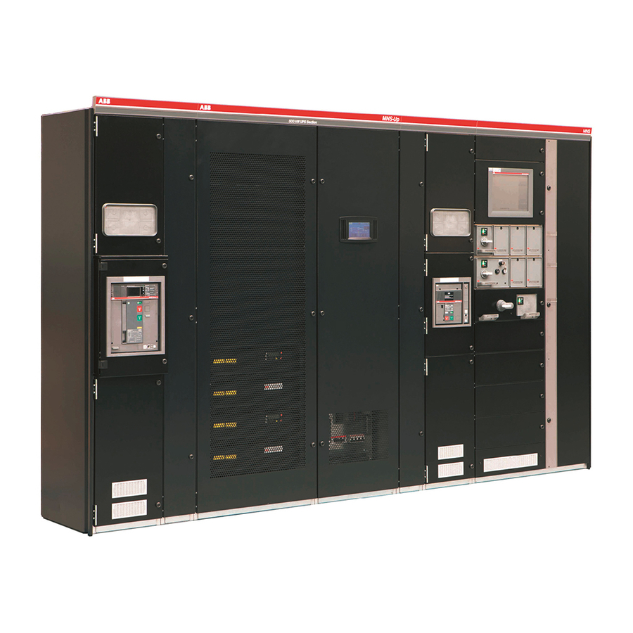
Page 15: Mns-Up Ups Section
System description 4.1 MNS-Up UPS section MNS-Up UPS SECTION OVERVIEW Input main busbar 3 pole Common battery connection bars Output main busbar 3 pole Ventilation chanel Input and output neutral conductor Partition wall 3 to main busbar area PE main busbar... - Page 16 A parallel MNS-Up system means the linking together requires for reliable operation. During longer blackouts and other of two or more MNS-Up units in parallel, so that in the unlikely power interruptions, batteries provide emergency power to safe- event that one fails, the other can automatically take up the load.
-
Page 17: Packing
– There is no connection of the transport frame with the packing material when using crates. Nails for fastening of wooden cross beams Shipping frame Wooden beams 8x10cm Wooden beams 8x10cm handing by forklift truck Box packing with cross beams MNS-Up Service Manual... -
Page 18: Shipping Unit With Transport Frame Or Euro Pallet
A protective drying agent according to DIN 55474 must be provided between the foil and the switchgear. No direct contact of this protective drying agent with the switchgear is allowed. With container traffic, no box packing is necessary. MNS-Up Service Manual... -
Page 19: Separate Packing
Withdrawable circuit breakers must be packed in the original transport boxes and shipped separately. MNS-Up UPS modules Active and passive MNS-Up modules must be removed from the MNS-Up section and packed in the original boxes before shipping. MNS-Up Filter modules ... -
Page 20: Transport
Transport 6.1 MNS-Up section – The MNS-Up sections must be shipped as individual sections, due to their dimensions and weight. – ACB sections and MNS 3.0 sections may be shipped in sections of max 3 m in length or 3 sections. Shipping sections shall only be transported in upright position –... -
Page 21: Mns-Up Modules
Frame corner joint with lifting angle 6.2 MNS-Up Modules The MNS-Up active and passive modules must be shipped in their original packing. Stacking of boxes is allowed, up to two boxes. 6.3 Circuit breakers Circuit breaker must be treated in the following way: Fixed circuit breaker must be additionally braced. -
Page 22: Erecting
In case of cable connection from bottom, the following floor cut-outs need to be provided: The holes in the gland plates need to be prepared on site, based on the number and cross section of the cables used. Floor cut-outs for MNS-Up ups section ... -
Page 23: Clearance Above Mns-Up System
7.2 Clearance above MNS-Up system The MNS-Up system uses forced ventilation to keep the UPS module temperature constant. The air inlet to the UPS section is from the front, the air outlet is on the top. Therefore, there must be a clear-ance of at least 100 cm above the MNS-Up UPS section. -
Page 24: Frame And Enclosure
7.4.1.3 EMC seals for bottom plate All MNS-Up sections require bottom plates due to EMC requirements. The bottom plates need to be fixed in a distance of 225 mm, and no additional EMC seals are required. 7.4.2 EMC seals for shipping splits UPS sections shall be joined with partition wall 19 between two MNS-Up sections, as well as between MNS-Up section and MNS sections. -
Page 25: Rear Walls And Side Walls
The connecting material to join the main busbar and PE busbars is part of the assessor pack delivered with each shipping section. Access to the shipping split is granted in the filter section of the MNS-Up section. To get access to the shipping split, all filter modules and partition wall 3 need to be removed. -
Page 26: Battery Connection
After joining the main busbars, the partition wall must be reinstalled and correctly fixed. The PE busbar is located in the front of the MNS-Up sections. The connection at shipping sections must be done according to the MNS service manual. -
Page 27: Individual Batteries
Combination of individual batteries and common battery connection Individual battery connection 7.6.2 Common batteries In case a common battery set must be connected to one MNS-Up section, the battery connection bars of the different module levels need to be connected using copper links. MNS-Up Service Manual... -
Page 28: Mns-Up Configuration
MNS-Up configuration 8.1 Single MNS-Up UPS section configuration A single section configuration requires one MNS-Up section equipped with 1-5 MNS-Up modules. The modules are feeding energy in parallel to the outgoing bar. Single section 1 module - 100kw installed Single section 2 modules in parallel – 200kw installed ... -
Page 29: Active, Passive And Filter Module Placing
Please check DPA500 user manual section 1.4.4. 8.3 Active, passive and filter module placing 8.3.1 Module arrangement The MNS-Up module sets must be installed from bottom to top. One module set consists of: – Passive module – Active module –... -
Page 30: Space Covers
The compartment of active and passive modules is mechanically coded to prevent wrong placement of active and passive modules. 8.3.2 Space covers Empty space compartments of active, passive and filter modules must be closed using the respective space covers. Space cover active passive module combination MNS-Up Service Manual... - Page 31 MNS-Up configuration 1TGB110488R0001 Space cover active passive module combination 1TGB100370r0101 MNS-Up Service Manual...
-
Page 32: Mns-Up Module Installation
9.2 Adding of module sets Wheelchair lifts are recommended for lifting modules up or down. MNS-Up modules are always installed as a complete set, since none of the modules can work independently. To install a new module set the following steps are recommended: Model: ... -
Page 33: Handling Of Emc Boards
Handling of EMC boards In each of the MNS-Up sections, two EMC boards are installed on the distribution bars. The boards are located behind the filter modules. To access the boards, all the filter modules must be removed. A complete system shutdown is required if emc boards must be accessed. - Page 34 Handling of EMC boards EMC board access in MNS-Up filter section Reassemble in the opposite way. Follow the startup procedure as described in the DPA500 user manual section 5.15.2.2. MNS-Up Service Manual...
-
Page 35: Communication Boards
Communication boards The communication boards are located below the control wiring duct in the MNS-Up module. Control wiring duct with integrated communication ports Communication ports in MNS-Up systems Modem Slot for optional Modem/Ethernet card ONLY SNMP Slot for optional SNMP card ONLY... -
Page 36: Mns 3.0 Sections
12.1 Incoming and outgoing feeders Incoming and outgoing feeder sections are an entire part of any MNS-Up system. The incoming feeder(s) are MNS 3.0 sections with ACBs. The incoming feeder and outgoing feeders for non-critical load are connected to the upper main busbar system. -
Page 37: Earthing Of Transformer/Generator Connection
12.2 Central manual bypass The central manual bypass is used to bypass the UPS system in case maintenance on the MNS-Up UPS modules is required. The central maintenance bypass can be closed even if the MNS-Up UPS modules are switched on. -
Page 38: Commissioning
Follow the commissioning procedure as described in the MNS service manual 1TGC902006M0404 section 3.12 Exception: While performing the insulation test on the main busbar system, the fuses of the EMC boards have to be disconnected. Follow the start-up procedure as described in the DPA 500 user manual section 6.7 MNS-Up Service Manual... -
Page 39: Operating Of Mns-Up System
Operating of MNS-Up system 14.1 MNS-Up system operation For operating instructions for the MNS-Up ups system please refere to the conceptpower DPA500 user manual doc no 04- 3275_abb_opmcp dpa-500 100 - 500kw_en. 14.2 Handling/operating ACBs For operating and maintenance on acbs check the respective service manuals supplied with the system. -
Page 40: Tightening Torques For Screw Connectionin Mns-Up
Tightening torques for screw connectionin MNS-Up 15.1 SeIf-tapping screws in plastic material Screw type Dim. Thermoplastics and duroplastics Ident. No Thermoplastics and duroplastics Set value Max. value Set value Max. value (nominal) (nominal) TORX pan head tap- ping screws 1TGB 000 116 P.. -
Page 41: Thread Rolling Screws In Metal
Tightening torques for screw connectionin MNS-Up 15.2 Thread rolling screws in metal Hexalobular socket pan Cross recessed pan head Hexagon socket head cap Hexalobular socket Hexagon head screws, head screw, ISO 14583 screws, ISO 7045 screws, ISO 4762 countersunk flat head screw,... -
Page 42: Screws For Busbar Connections (Cu) And System Connections (Steel/Steel)
Tightening torques for screw connectionin MNS-Up 15.3 Screws for busbar connections (Cu) and system connections (steel/steel) Hexagon head screws, fully threaded, ISO 4017 Screw type Tightening torques Set value Max. value Ident no (nominal) Hex socket head cap screws DIN00912 with ESLOK GILN 200 124 P... -
Page 43: Spare Parts
Description ID No. Additional information MNS-Up active module 04-3404 MNS-Up passive module 04-3405 MNS-Up filter module 1TGB100355R0001 MNS-Up EMC filter module 1TGB100363R1000 MNS-Up communication boards 04-3862 § Parallel adapter boards 04-3862 § SNMP board 04-0594 § Profibus card MNS-Up HMI... -
Page 44: Maintenance Intervals
A distinction is made between the following installation categories, because the frequency of maintenance or inspection depends on the operating conditions: Installation category A: Normal operation Installation category B: Heavy-duty operation, e.g. cement factory Installation category C: Short circuit (fault) MNS-Up Service Manual... -
Page 45: Maintenance Checklist
§ Arrangement of modules in equipment accordance with engineering § Internal conditions documents Clean § Contamination, e.g. dust m: monthly n: insertion cycles of modules a: annually x: test in the event of a fault (e.g. after a short-circuit) MNS-Up Service Manual... - Page 46 Check measuring loops § In accordance with circuit diagram 1.3.9 Check function of the See ConceptpowerDPA500 manual MNS-Up modules and bat-teries m: monthly n: insertion cycles of modules a: annually x: test in the event of a fault (e.g. after a short-circuit)
- Page 47 § Protective conductor § Condition of the roller in the connection compartment bottom plate m: monthly n: insertion cycles of modules a: annually x: test in the event of a fault (e.g. after a short-circuit) MNS-Up Service Manual...
- Page 48 —Check screwed connections connec-tions —Check cable strain relief —Cable routing, min. bending radii, edge protection, etc. m: monthly n: insertion cycles of modules a: annually x: test in the event of a fault (e.g. after a short-circuit) MNS-Up Service Manual...
- Page 49 ABB Schweiz Lenzburg, notice. With regard to purchase orders, the agreed Switzerland particulars shall prevail. ABB does not accept Local Contacts on any responsibility whatsoever for potential errors or www.abb.com/mns possible lack of information in this document.