ABB IRB 6620 Product Specification
Articulated robot
Hide thumbs
Also See for IRB 6620:
- Product manual (360 pages) ,
- Product manual, spare parts (28 pages) ,
- Operating manual (20 pages)
Table of Contents
Advertisement
Quick Links
Advertisement
Table of Contents

Related Manuals for ABB IRB 6620


Summary of Contents for ABB IRB 6620
- Page 1 Product specification Articulated robot IRB 6620-150/2.2 M2004...
- Page 3 Product specification Articulated robot 3HAC025861-001 Rev.E IRB 6620 - 150/2.2 M2004...
- Page 4 Except as may be expressly stated anywhere in this manual, nothing herein shall be construed as any kind of guarantee or warranty by ABB for losses, damages to persons or property, fit- ness for a specific purpose or the like.
-
Page 5: Table Of Contents
Table of Contents Overview 1 Description 1.1 Structure ............... . .7 1.1.1 Introduction . - Page 6 Table of Contents 2.3 Type H................61 2.3.1 Introduction .
- Page 7 Overview Overview About this Product specification It describes the performance of the manipulator or a complete family of manipulators in terms of: • The structure and dimensional prints • The fulfilment of standards, safety and operating requirements • The load diagrams, mounting of extra equipment, the motion and the robot reach •...
- Page 8 Overview Complementary documentation Product Description specification Controller IRC5 with FlexPendant, 3HAC021785-001 Controller Software RobotWare 5.11, 3HAC022349-001 IRC5 Robot User Documen- IRC5 and M2004, 3HAC024534-001 tation Product Manual Description Manipulator IRB 6620, 3HAC027151-001 SpotPack/DressPack 3HAC027309-001 Rev.E 3HAC 025861-001...
-
Page 9: Description
Based on the famous IRB 6600 robot family, with the highly flexible bending backwards concept, the very high wrist torque, the service friendly modular built up and the very high availability, significant for ABB’s robots, the IRB 6620 goes even further, towards the excellence as a flexible tooling in automatic manufacturing. -
Page 10: The Robot
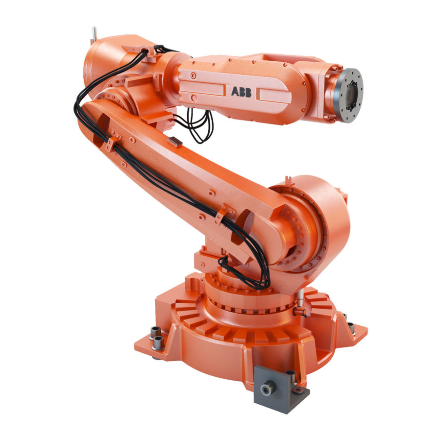
Figure 1 The IRB 6620 manipulator has 6 axes. 1.1.2 The Robot General The IRB 6620 can be mounted on to the floor or inverted, a tilting of ± 15º is allowed for both mountings. Robot Type Handling capacity (kg) - Page 11 Dimensions IRB 6620 400,5 575 (B) 575 (B) Figure 2 View of the IRB 6620 manipulator from the front, side rear and above (dimensions in mm). Allow 200 mm behind the manipulator for DressPack. Description R 199 mm for wrist rotation...
-
Page 12: Safety/Standards
1 Description 1.2.1 Standards 1.2 Safety/Standards 1.2.1 Standards The robot conforms to the following standards: Standard Description EN ISO 12100 -1 Safety of machinery, terminology EN ISO 12100 -2 Safety of machinery, technical specifications EN 954-1 Safety of machinery, safety related parts of control Systems EN 60204 Electrical equipment of industrial machines EN ISO 60204-1:2005... - Page 13 1 Description 1.2.1 Standards The robot complies fully with the health and safety standards specified in the EEC’s Machinery Directives. Safety function Description The Service The service information system gathers information about the Information System robot’s usage and determines how hard the robot is used. The (SIS) usage is characterized by the speed, the rotation angles and the load of every axis.
- Page 14 1 Description 1.2.1 Standards The Active Safety Description System The Self Tuning The Process Robot Generation is designed to run at different load Performance (STP) configurations, many of which occur within the same program and cycle. The robot’s installed electrical power can thus be exploited to lift heavy loads, create a high axis force or accelerate quickly without changing the configuration of the robot.
- Page 15 1 Description 1.2.1 Standards The Passive Safety Description System Electronic Position EPS offers axes position status signals, fulfilling applicable Switches (EPS) on up regulations for personnel safety. Five outputs can each be to 7 axes (option) configured to reflect the position of a single axis or a combination of axes.
-
Page 16: Installation
1.3.1 Introduction General The IRB 6620 can be mounted on to the floor or inverted. Both can be tilted to ± 15º. A tool or an end effector with max. weight of 150 kg including payload, can be mounted on the robot tool flange (axis 6). See Load diagram 1.5.2... -
Page 17: Operating Requirements
1 Description 1.3.2 Operating requirements 1.3.2 Operating requirements Protection standards Standard Manipulator IP54, Foundy Plus IP67. Explosive environments The robot must not be located or operated in an explosive environment. Ambient temperature Description Standard/Option Temperature Manipulator during Standard + 5°C (41°F) to + 50°C (122°F) operation For the controller Standard/Option... -
Page 18: Mounting The Manipulator
1 Description 1.3.3 Mounting the manipulator 1.3.3 Mounting the manipulator Maximum Load Maximum load in relation to the base coordinate system. Endurance load in operation Max. load at emergency stop Force xy ± 7.3 kN ± 15.5 kN Force z 11.0 ±... - Page 19 1 Description 1.3.3 Mounting the manipulator Fastening holes robot base Figure 4 Hole configuration (dimensions in mm). Recommended screws for fastening the M24 x 100 8.8 with 4 mm flat washer manipulator to the base Torque value 775 Nm Only two guiding sleeves shall be used. The corresponding holes in the base plate shall be circular and oval according to Figure 5 and Figure 6.
- Page 20 1 Description 1.3.3 Mounting the manipulator Regarding AbsAcc performance, the chosen guide holes according to Figure 4 and Figure 8 are recommended. Base plate drawing Figure 5 Base plate dimension print, main dimensions and holes measurements (dimensions in mm). Description Color: RAL 9005 Thickness: 80-100 μm Rev.E...
- Page 21 1 Description 1.3.3 Mounting the manipulator Figure 6 Base plate dimension print, measurements of the adaption for the robot base (dimension in mm). 3HAC 025861-001 Rev.E...
- Page 22 1 Description 1.3.3 Mounting the manipulator Two guiding sleeves required, dimensions see Figure 7 Figure 7 Sections of base plate and guide sleeve (dimensions in mm). Description Guide sleeve protected from corrosion Figure 8 Sections of base plate (dimensions in mm). Rev.E 3HAC 025861-001...
-
Page 23: Calibration And References
1 Description 1.4.1 Fine calibration 1.4 Calibration and references 1.4.1 Fine calibration General Fine calibration is made using the Calibration Pendulum, please see Operating manual - Calibration Pendulum. Figure 9 All axes in zero position. Calibration Calibration Position Calibration of all axes All axes are in zero position Calibration of axis 1 and 2 Axis 1 and 2 in zero position... -
Page 24: Absolute Accuracy Calibration
Absolute Accuracy (AbsAcc) is a calibration concept, which ensures a TCP absolute accuracy of better than ± 1 mm in the entire working range (working range of bending backward robots, eg IRB 6620, are limited to only forward positions). Absolute accuracy compensates for: •... - Page 25 Absolute Accuracy is a TCP calibration in order to Reach (m) a good positioning in the Cartesian coordinate system. Figure 10 The Cartesian coordinate system Production data Typical production data regarding calibration are: Positioning accuracy (mm) Robot Average % Within 1 mm IRB 6620-150/2.2 0.5 mm 0.95 mm 100% 3HAC 025861-001 Rev.E...
-
Page 26: Robot References
Figure 12 Seven holes B, on a radius of x mm from axis 6 center on the insulated tool flange. Figure 13 Detailed view of Tool Flange. Radius X (mm) for references on tool flange Robot Standard Insulated IRB 6620 - 150/2.2 R=81,5 R=101,5 Rev.E 3HAC 025861-001... -
Page 27: Load Diagrams
At different arm load, payload and moment of inertia, the load diagram will be changed. Control of load case by “RobotLoad” For an easy check of a specific load case, use the calculation program ABB RobotLoad. Please contact your local ABB organization. 3HAC 025861-001... -
Page 28: Diagrams
1 Description 1.5.2 Diagrams 1.5.2 Diagrams IRB 6620-150/2.2 Figure 14 Maximum permitted load mounted on to the robot tool flange at different positions (center of gravity). Rev.E 3HAC 025861-001... - Page 29 1 Description 1.5.2 Diagrams IRB 6620-150/2.2 “Vertical Wrist” (±10 Figure 15 Maximum permitted load mounted on the robot tool flange at different positions (center of gravity) at “Vertical Wrist” (±10 ), J =15 kgm For wrist down (0 deviation from the vertical line).
-
Page 30: Maximum Load And Moment Of Inertia For Full And Limited Axis 5 (Center Line Down)
), see Figure 16 Full movement of axis 5 Axis Robot Type Maximum moment of inertia ) ≤ 138 kgm IRB 6620-150/2.2 Ja5 = Load x ((Z + 0,200) ) + max (J ≤ 107 kgm IRB 6620-150/2.2 Ja6 = Load x L Figure 16 Moment of inertia when full movement of axis 5. -
Page 31: Wrist Torque
Also arm loads will influence the per- mitted load diagram. For finding the absolute limits of the load diagram, please use the ABB RobotLoad. Please contact your local ABB organization. -
Page 32: Mounting Of Equipment
1 Description 1.6.1 General 1.6 Mounting of equipment 1.6.1 General Extra loads can be mounted on the upper arm housing and on the frame. Definitions of distances and mass are shown in Figure 18. The robot is supplied with holes for mounting extra equipment (see Figure 19 and Figure 20). - Page 33 1 Description 1.6.1 General Frame Permitted extra load on the frame is 100 kg. Holes for mounting extra equipment Figure 19 Holes for mounting extra equipment. 3HAC 025861-001 Rev.E...
- Page 34 1 Description 1.6.1 General Figure 20 Holes for mounting of extra equipment. Rev.E 3HAC 025861-001...
- Page 35 1 Description 1.6.1 General Robot Tool Flange Figure 21 Robot tool flange SS-EN ISO 9409-1:2004 (dimensions in mm). Description Minimum thread length for screws in M12-hole is 9 mm. Ø 12 H7 Depth 15 Ø 100 H7 Depth 8 min For fastening of Gripper tool flange to Robot tool flange every other one of the bolt holes for 6 bolts quality class 12.9 shall be used (see Figure 21).
-
Page 36: Maintenance And Troubleshooting
1 Description 1.7.1 Introduction 1.7 Maintenance and Troubleshooting 1.7.1 Introduction General The robot requires only minimum maintenance during operation. It has been designed to make it as easy to service as possible: • Maintenance-free AC motors are used. • Oil is used for the gear boxes. •... -
Page 37: Robot Motion
1.8.1 Introduction 1.8 Robot Motion 1.8.1 Introduction Type of Motion Range of movement Axis Type of motion IRB 6620-150/2.2 Rotation motion + 170° to - 170° Arm motion + 140° to - 65° Arm motion + 70° to - 180°... - Page 38 1 Description 1.8.1 Introduction Limitations Axis 5 with DressPack Holder Due to the DressPack holder at Axis 6 there are the following limitations for Axis 5 movement when DressPack Upper arm is used. See Figure 22. Figure 22 Limitations for Axis 5 when using DressPack holder. Description Different limitations for the DressPack Holder are due to the asymmetric fork of the robot wrist.
- Page 39 1 Description 1.8.1 Introduction Robot Type Handling capacity (kg) Reach (m) IRB 6620-150/2.2 Figure 23 The extreme positions of the robot arm specified at the wrist center (dimensions in mm). 3HAC 025861-001 Rev.E...
-
Page 40: Performance According To Iso 9283
1 Description 1.8.2 Performance according to ISO 9283 1.8.2 Performance according to ISO 9283 General At rated maximum load, maximum offset and 1.6 m/s velocity on the inclined ISO test plane, 1 m cube with all six axes in motion. The figures for AP, RP, AT and RT are mesured according to Figure 24. -
Page 41: Velocity
Maximum axis speeds Robot Type Axis 1 Axis 2 Axis 3 Axis 4 Axis 5 Axis 6 IRB 6620-150/2.2 100°/s 90°/s 90°/s 150°/s 120°/s 190°/s There is a supervision function to prevent overheating in applications with intensive and frequent movements. -
Page 42: Servo Gun
1 Description 1.9.1 Introduction 1.9 Servo Gun 1.9.1 Introduction General The robot can be supplied with hardware and software for control of the following configurations: • Stationary Gun • Robot Gun • Robot Gun and Track Motion • Track motion The specific parts related to the servo motor control for electrical welding guns and for track motion configurations are shown in the conceptual pictures below. -
Page 43: Stationary Gun
1 Description 1.9.2 Stationary Gun 1.9.2 Stationary Gun Figure 25 Configuration of Stationary Gun. Options Options according to the table below are required to complete the delivery. For further details on each option see corresponding Product specification. Product Option Description specification 785-5 Stationary gun.This option includes:... -
Page 44: Robot Gun
1 Description 1.9.3 Robot Gun 1.9.3 Robot Gun Figure 26 Configuration of Robot Gun. Options Options according to table below are required to complete the delivery. For further details on each option see corresponding Product specification. Product Option Description specification 785-1 Robot gun. -
Page 45: Robot Gun And Track Motion
785-1 + 1002-8 Robot Gun + Track Motion. This option Track motion includes: IRBT 6004 + IRB 6620 Cables within manipulator for servo power signals (servo gun/axis 7). Track motion deliv- Serial measurement box (SMB2, Split box) Track motion ery includes for distribution of servo power to axis 7 and 8. -
Page 46: Track Motion Irbt 6004
1 Description 1.9.5 Track Motion IRBT 6004 1.9.5 Track Motion IRBT 6004 General The robot can be supplied with a Track Motion, see Product specification - IRBT 6004. For configuration and specification of hardware see Figure 28. Figure 28 Configuration of Track Motion. General. -
Page 47: Dresspack And Spotpack
2 DressPack and SpotPack 2.1.1 General 2 DressPack and SpotPack 2.1 Introduction 2.1.1 General DressPack Includes options for Upper arm, Lower arm and Floor pos and D, see Figure 29. These are described separately below but are designed as a complete package for various applications. - Page 48 2 DressPack and SpotPack 2.1.1 General Figure 29 DressPack/Spotpack. Description SpotPack, Spot Welding cabinet Robot controller, (including 7th axis drive for servo gun) DressPack, Floor DressPack, Routing base to Axis 6 SpotPack, Water and Air unit Rev.E 3HAC 025861-001...
-
Page 49: Product Range
2 DressPack and SpotPack 2.1.2 Product range 2.1.2 Product range DressPack solutions for different user’s needs The robot can be equipped with the well integrated cable and hose packages in the SpotPack or DressPack options. The DressPack is designed in close conjunction with the development of the manipulator and is therefore well synchronized with the robot. -
Page 50: Limitations Of Robot Movements
In bending backwards positions there are limitations due to inteference with manipula- tor or Water and Air unit (if such is mounted). For more detail information please contact Serop Product support/SEROP/ABB. E-mail address: serop.product_support@se.abb.com 2.1.4 Impact on dress pack lifetime There are some robot movements/positions that shall be avoided in the robot produc- tion program. -
Page 51: Chapter Structure
2 DressPack and SpotPack 2.1.5 Chapter Structure 2.1.5 Chapter Structure The Chapters for SpotPack and DressPack are structured in the following way. The SpotPack and DressPack can be delivered in three versions developed for two different applications. Each type is described under separate chapter. Chapter Option Description... -
Page 52: Dresspack
2 DressPack and SpotPack 2.2.1 Introduction 2.2 DressPack 2.2.1 Introduction Available DressPack configurations for Material Handling The table below shows the different DressPack configurations available for Material Handling. Figure 31 Available options for Material handling. Available DressPack configurations for Spot Welding The table below shows the different DressPack configurations available for Spot Welding. - Page 53 2 DressPack and SpotPack 2.2.1 Introduction DressPack lower arm For the Material Handling application there is one routing for the lower arm, shown below in Figure 33. This is designed to fit to the upper arm routing. Figure 33 DressPack Lower arm right side view Material Handling (option 778-1 and option 798-1). Description Connection point at axis 3 DressPack Upper arm...
- Page 54 2 DressPack and SpotPack 2.2.1 Introduction DressPack Upper/Lower arm For Spot Welding application there are two additional alternative available, one without connection point between lower and upper arm and one with connection point only for signals, see Figure 35 and Figure 36. Figure 35 External with retract arm (option 778-2 and option 781-1).
-
Page 55: Build-In Features For Upper Arm Dresspack
2 DressPack and SpotPack 2.2.2 Build-in features for upper arm DressPack 2.2.2 Build-in features for upper arm DressPack External Material handling (option 780-3): • Internal routing through the rear part of the upper arm. • Protection hose can easily be replaced if damaged. •... -
Page 56: Interface Description For Dresspack
Below is an overview showing the different dresspack interfaces. For detailed infor- mation see the circuit diagram included in the Product Manual DressPack/SpotPack IRB 6620, art No. 3HAC027309-001. 2.2.3.1 Connection at robot base Material handling (option 798-1), see Figure 37: •... - Page 57 2 DressPack and SpotPack 2.2.3 Interface description for DressPack Figure 38 Connection point at base for option 781-2. Description R1.CP/CS R1.SP (Spot Welding Servo gun) R1.PROC 1 (Material Handling/Spot Welding 1/2”, M22x1.5, 24 degree seal) R1.PROC 2 - 4 (Spot Welding 1/2”, M22x1.5, 24 degree seal) R1.WELD 3x25mm .
- Page 58 2 DressPack and SpotPack 2.2.3 Interface description for DressPack Figure 39 Souriau connetor external routing (UTOW61419SH shown). Spot welding (option 781-2), see Figure 40: • Hose and cable free length, 1000 mm. • Hoses and weld power cable end with free end. •...
- Page 59 2 DressPack and SpotPack 2.2.3 Interface description for DressPack External with retract arm Spot welding/Material handling (option 781-1), see Figure 41: • Hose and cable free length, min. 1000 m. • Hoses and weld power cable (only for spot welding) end with free end. •...
- Page 60 2 DressPack and SpotPack 2.2.3 Interface description for DressPack Dimensions Dimensions are shown in Figure 42 to Figure 43. Figure 42 External routing Material Handling, option 798-1 and 780-3 (Dimensions in mm). Rev.E 3HAC 025861-001...
- Page 61 2 DressPack and SpotPack 2.2.3 Interface description for DressPack Figure 43 External with retract arm option 781-1 (Dimensions in mm). 3HAC 025861-001 Rev.E...
- Page 62 2 DressPack and SpotPack 2.2.3 Interface description for DressPack Figure 44 External, 781-2 Figure showing IRB 6640 (Dimensions in mm). Description Holder arm house Holder axis 6 Rev.E 3HAC 025861-001...
-
Page 63: Type H
2 DressPack and SpotPack 2.3.1 Introduction 2.3 Type H 2.3.1 Introduction General Variant Type H is designed for Material Handling (MH) application. Included modules are shown in Figure 45. Figure 45 Dresspack, Routing base to Axis 6. Pos. Name Robot Cabinet IRC5 DressPack, Floor: Connection of Parallel Communication, Can/DeviceNet or Profibus DressPack, Routing base to Axis 6... - Page 64 2 DressPack and SpotPack 2.3.1 Introduction Available configurations with linked option numbers are described below. Option description Option Type Description 16-1 Connection to cabinet Floor cables and connections inside the I/O section for the DressPack are chosen. The length and con- figuration of the floor harness is specified under the options below.
- Page 65 2 DressPack and SpotPack 2.3.1 Introduction The available alternatives and allowed combinations are shown in the schematic Figure 46 below. Figure 46 Schematic picture for configuration of DressPack for Material Handling application. 3HAC 025861-001 Rev.E...
-
Page 66: Configuration Result For Type H
2 DressPack and SpotPack 2.3.2 Configuration result for Type H 2.3.2 Configuration result for Type H General Depending on the choice of options above the DressPack will have different content. The choice of routing will not affect the content. See tables for signal content below. DressPack. - Page 67 2 DressPack and SpotPack 2.3.2 Configuration result for Type H Parallel and Can/DeviceNet The table below shows the available type of wires/media. Connection Cable/ Allowed Type terminals point. Base, part area capacity in cabinet axis 6 Customer Power (CP) Utility Power 0,5 mm 250 VAC, 5 A rms Protective earth...
- Page 68 2 DressPack and SpotPack 2.3.2 Configuration result for Type H Parallel and Profibus The table below shows the available type of wires/media. connection Cable/ Allowed Type terminals point. Base, part area capacity in cabinet axis 6 Customer Power (CP) Utility Power 0,5 mm 250 VAC, 5 A rms Protective earth...
-
Page 69: Type Se
2 DressPack and SpotPack 2.4.1 Introduction 2.4 Type Se 2.4.1 Introduction General Variant Type Se is designed for Spot Welding (SW) application with robot handled servo-controlled tool (electrical gun). Included modules are shown in Figure 47. Available configurations with linked option numbers are described below. Figure 47 Type Se with Routing base to Axis 6. - Page 70 2 DressPack and SpotPack 2.4.1 Introduction Option Description Option Type Description 16-1 Connection to Floor cables and connections inside the I/O section for the cabinet DressPack are chosen. The length and configuration of the floor harness is specified under the options below. Option 94-1,-2,-3,-4 for parallel communication Option 90-2,-3,-4,-5 for parallel communication and field bus communication with Can/DeviceNet...
- Page 71 2 DressPack and SpotPack 2.4.1 Introduction The available alternatives and allowed combinations are shown in the schematic Figure 48 below. Figure 48 Schematic picture for configuration of DressPack for Spot Welding application. 3HAC 025861-001 Rev.E...
-
Page 72: Configuration Result For Type Se
2 DressPack and SpotPack 2.4.2 Configuration result for Type Se 2.4.2 Configuration result for Type Se General Depending on the choice of options above the DressPack will have different content. The choice of routing will not affect the content. See tables for signal content below. DressPack. - Page 73 2 DressPack and SpotPack 2.4.2 Configuration result for Type Se Parallel and Can/DeviceNet The table below shows the available type of wires/media. connection Cable/ Allowed Type terminals point. Base, part area capacity in cabinet axis 6 Customer Power (CP) Utility Power 0,5 mm 250 VAC, 5 A rms Protective earth...
- Page 74 2 DressPack and SpotPack 2.4.2 Configuration result for Type Se Parallel and Profibus The table below shows the available type of wires/media. connection Cable/ Allowed Type terminals point. Base, part area capacity in cabinet axis 2/3 or axis 6 Customer Power (CP) Utility Power 0,5 mm 250 VAC, 5 A rms...
- Page 75 Option 727-1. 24V 8 Amps power supply Required options for servo gun To enable the spot welding function package SpotPack IRB 6620 to run with a servo controlled gun, some additional (additional to those described in previous section “Required general options”) servo drive options are required. These standard options are described under other chapters and are also mentioned below in this chapter.
- Page 76 2.4.2 Configuration result for Type Se Required Spot Welding cabinet options The SpotPack IRB 6620 also requires a Spot Welding cabinet (option 768-3) to perform as intended. There are three different variants (see below) of Spot Welding cabinets available. Weld timer brand and weld capacity are stated by choosing one of the optional variants.
- Page 77 Only together with option 781-2. Required Water and Air unit options The SpotPack IRB 6620 also requires Water and Air unit options to perform as intended. These options are further described under chapter 2.7 Water and Air unit and are also mentioned in this chapter.
-
Page 78: Type Hse
2 DressPack and SpotPack 2.5.1 Introduction 2.5 Type HSe 2.5.1 Introduction General Variant Type HSe is designed for Material Handling (MH) against a stationary mounted Spot Welding servo controlled tool (electrical gun). Included main modules are shown in Figure 51 below. Available configurations with linked option numbers are described below starting with the DressPack. - Page 79 2 DressPack and SpotPack 2.5.1 Introduction Available configurations with linked option numbers are described below. Option description Option Type Description 16-1 Connection to Floor cables and connections inside the I/O section for the cabinet DressPack are chosen. The length and configuration of the floor harness is specified under the options below.
- Page 80 2 DressPack and SpotPack 2.5.1 Introduction The available alternatives and allowed combinations are shown in the schematic Figure 52 below. Figure 52 Schematic picture for configuration of DressPack for Material Handling application. Rev.E 3HAC 025861-001...
-
Page 81: Configuration Result For Type Hse
2 DressPack and SpotPack 2.5.2 Configuration result for Type HSe 2.5.2 Configuration result for Type HSe General Depending on the choice of options above the DressPack will have different content. The choice of routing will not affect the content. See tables for signal content below. Parallel communication The table below shows the available type of wires/media. - Page 82 2 DressPack and SpotPack 2.5.2 Configuration result for Type HSe Parallel and Can/DeviceNet The table below shows the available type of wires/media. Connection Cable/ Allowed Type terminals point. Base, part area capacity in cabinet axis 6 Customer Power (CP) Utility Power 0,5 mm 250 VAC, 5 A rms Protective earth...
- Page 83 2 DressPack and SpotPack 2.5.2 Configuration result for Type HSe Parallel and Profibus The table below shows the available type of wires/media. Connection Cable/ Allowed Type terminals point. Base, part area capacity in cabinet Axis 2/3 or axis 6 Customer Power (CP) Utility Power 0,5 mm 250 VAC, 5 A rms...
- Page 84 Option 727-1. 24V 8 Amps power supply Required options for servo gun To enable the spot welding function package SpotPack IRB 6620 to run with a servo controlled gun, some additional (additional to those described in previous section “Required general options”) servo drive options are required. These standard options are described under other chapters and are also mentioned below in this chapter.
- Page 85 2 DressPack and SpotPack 2.5.2 Configuration result for Type HSe Option Type Description 782-7 Bosch Basic MFDC This option gives a basic Spot Welding cabinet equipped with a weld timer from Bosch with an integrated inverter with basic capacity. Type Bosch PSI 6100.630L1. Additional options to the different Spot Welding cabinets are mentioned below.
-
Page 86: Interface Description Stationary Gun
R3.FB7 to stationary gun and ends with 8 pin Souriau connector (Type UT 06128SH). • The connector configurations are described in the circuit diagram included in the Product Manual DressPack/SpotPack IRB 6620, art No. 3HAC027309- 001. The Harting connector is shown below. The different main parts within the connector are showed both with name and Harting article number. - Page 87 2.5.3 Interface description stationary gun Required Water and Air unit options The SpotPack IRB 6620 also requires Water and Air unit options to perform as intended. These options are further described under chapters 2.7 Water and Air unit and are also mentioned in this chapter.
-
Page 88: Spot Welding Cabinet
2 DressPack and SpotPack 2.6.1 Introduction 2.6 Spot Welding cabinet 2.6.1 Introduction General The Spot Welding cabinet for SpotPack contains the electric components and circuits needed for spot welding application. The Spot Welding cabinet, with the welding controller built in, is controlled from the robot controller via the process software. The capacity and functionality depends on the choice of different option combina- tions. - Page 89 2 DressPack and SpotPack 2.6.1 Introduction Figure 56 Exploded view drawing of the Spot Welding cabinet. 3HAC 025861-001 Rev.E...
- Page 90 2 DressPack and SpotPack 2.6.1 Introduction Figure 57 Different views of the Spot Welding cabinet (dimensions in mm). The electrical circuits of the Spot Welding cabinet consist of weld power circuit and control circuits to control the welding. Rev.E 3HAC 025861-001...
- Page 91 2 DressPack and SpotPack 2.6.1 Introduction Weld power circuit The welding power for the welding gun is fed through a circuit breaker and welding thyristor (for AC welding) or inverter (for MFDC welding) and further out to the welding power cable. The cabinet is prepared for power feeding from the floor or from top.
- Page 92 400-600 V AC Max welding current 130 A rms, 100 kVA transformer Max wire range, incoming power 3 x 70 mm Main breaker (ABB Sace T1), thermal release 160 A (adjustable) 110-160 A Main breaker, magnetic release 36 kA Protection class IP54 Figure 58 Spot Welding cabinet equipped with a weld timer from Bosch.
- Page 93 3 x 70 mm Power feeding 400-480 V AC Max welding current 110 A rms, 20 kA weld current Main breaker (ABB Sace T1), thermal release 160 A (adjustable) 110-160 A Main breaker, magnetic release 36 kA Protection class IP54 Option 828-1 Region A Offers 120 V power supply.
- Page 94 2 DressPack and SpotPack 2.6.1 Introduction Option 788-1 Forced air cooling Offers a cooling fan with housing placed on the rear of the Spot Welding cabinet which forces air on the cooling surface/grids of the thyristor or MFDC inverter (see pictures below).
- Page 95 2 DressPack and SpotPack 2.6.1 Introduction Option 790-1 Contactor for weld power Offers a weld contactor with necessary wiring placed inside the Spot Welding cabi- net. The contactor is mounted after the thyristor or inverter and opens up the weld circuit out from the cabinet.
-
Page 96: Interface Description Spot Welding Cabinet
35 mm Max. 600 VAC, tive earth 150 A rms at + 20°C (68°F) ambient temperature a. Incoming power connection made by customer. For incoming power and safety recommendations see the Product Manual DressPack/SpotPack IRB 6620 3HAC027309-001 Rev.E 3HAC 025861-001... - Page 97 2 DressPack and SpotPack 2.6.2 Interface description Spot Welding cabinet Connections for Signals Type Specification Allowed capacity Water and air unit Modular Harting connector, 24 V DC, Max 0,5 A / output (XS 103) type DD Stationary gun Modular Harting connector, 24 V DC, Max 0,5 A / output (XS 104) type HD...
-
Page 98: Water And Air Unit
2 DressPack and SpotPack 2.7.1 Introduction 2.7 Water and Air unit 2.7.1 Introduction General The Water and Air unit contains components for water and air distribution and control within the SpotPack. The water and air unit is controlled from the robot controller via the process software. - Page 99 2 DressPack and SpotPack 2.7.1 Introduction Water in circuit The function of the water in circuit is to open / close the cooling water supply to the Spot welding gun (see Figure 62). An electrical 2 port solenoid valve is used. The valve is controlled by a digital signal from the robot control system.
- Page 100 2 DressPack and SpotPack 2.7.1 Introduction Water return circuit The water return circuit monitors the flow of the returning cooling water from the Spot welding gun (see Figure 63). The flow switch detects if the water flow is too low in the cooling water circuit. The flow switch gives a digital signal to the robot control system, which automatically shuts off the electrical shut off valve in the water in circuit if the flow is too low.
- Page 101 2 DressPack and SpotPack 2.7.1 Introduction Air supply circuit The air supply circuit provides the function package with filtered air (see Figure 64). The air supply circuit begins with a internal G ½" thread, manually operated shut off valve with residual pressure release though a silencer, air filter with nominal filtration of 5 µm with a metal protection of the bowl, a digital pressure switch and a cross interface containing plugged air outlet ports (internal G 3/8"...
- Page 102 2 DressPack and SpotPack 2.7.1 Introduction Split box/Connection box With the split box, the 24VDC supply and signals are connected and distributed to the different units on the water and air unit, see Figure 65. The design makes disconnection of separate items for service and repair on the water and air unit very easy.
- Page 103 2 DressPack and SpotPack 2.7.1 Introduction Mounting Type S, robot mounted spot welding gun, is mounted at the robot at factory and water and air hoses are included and connected to the robot base. Figure 67 Water and air unit mounted on the base. Type HS, robot handles part against a pedestal mounted spot welding gun, the Water and Air panel is delivered in a together with the robot.
- Page 104 2 DressPack and SpotPack 2.7.1 Introduction Signals for water and air unit Electrical connections to robot I/O board are made via the Split box on the Water and Air unit or to connection box at robot base (Figure 69 shows Split box. For connection box see Circuit diagram.) 8 x M12 connections (4 pins) are available.
- Page 105 2 DressPack and SpotPack 2.7.1 Introduction Option Type Description 792-1 Water and Air unit, type S The basic water and air unit for type S is equipped for a robot handled gun and with the following components: Water in circuit Water return circuit Air supply circuit Split box...
-
Page 106: Technical Data Water And Air Unit
2 DressPack and SpotPack 2.7.2 Technical data Water and Air unit 2.7.2 Technical data Water and Air unit Media interface description The interface towards the Water and Air unit is described in table below. Type Specification Incoming water G 1/2” thread Outgoing water G 1/2”... -
Page 107: Tip Dresser
The Tip Dresser is controlled by the robot controller. The unit is mounted onto the base of the manipulator and is connected to the robot. The Tip Dresser unit The ABB Tip Dresser, which is integrated to the robot consists of the following modules (see Figure 70). Figure 70 The robot integrated Tip Dresser. - Page 108 2 DressPack and SpotPack 2.8.1 Introduction Mounting positions The Tip dressing unit (pos B, C and D) can be rotated 360° on the horizontal tube at the Adjustable stand (pos A). See Figure 71. The complete Tip Dresser (pos A, B, C and D) is mounted with 2 x M20 x 40, 120 Nm on to one of the four bolt ears on the robot base.
- Page 109 2 DressPack and SpotPack 2.8.1 Introduction Figure 72 Mounting positions of the complete Tip Dresser. For more information about settings, etc. see Product Manual - DressPack/SpotPack for IRB 6620, 3HAC027309-001 Selecting option 807-1 Tip Dresser the following parts are supplied: • motor •...
- Page 110 Highest sharpening - ABB trimmed Tip Dresser results - “Home position” and adjustment in Z-direction of the cutting unit. - Easy to change cutting blades. For more information see the Product manual - DressPack/SpotPack for IRB 6620, 3HAC027309-001 Rev.E 3HAC 025861-001...
-
Page 111: Connection Kits
2 DressPack and SpotPack 2.9.1 Options 2.9 Connection kits 2.9.1 Options Option 459-1, CP/CS, Proc 1 on base R1. CP/CS and Proc 1 on base. This option offers a kit with connectors. This must be assembled by the customer. The kit contains: •... - Page 112 2 DressPack and SpotPack 2.9.1 Options Option 453-1, FB 7 R3. FB 7 on base This option offers a kit with a connector. This must be assembled by the customer. The kit contains: • Connector with: 1 pcs Multiple connector (pin) Souriau 1 pcs Adaptor 8 pin...
- Page 113 2 DressPack and SpotPack 2.9.1 Options Option 458-1, CP/CS, Proc 1 axis 3 R2. CP/CS and Proc 1 on axis 3 This option offers a kit with connectors. This must be assembled by the customer. The kit contains: • 1 Hose fittings (Parker Pushlock, (½”, M22x1,5 Brass, 24 degree seal)) •...
- Page 114 2 DressPack and SpotPack 2.9.1 Options Option 543-1, CP/CS/CBus, Proc 1 axis 6 Harting CP/CS/CBus, Proc 1 axis 6 on tool side for option 781-1. This kit offers a kit with connectors to be mounted at tool side of axis 6. This must be assembled by the customer.
- Page 115 2 DressPack and SpotPack 2.9.1 Options Souriau CP/CS/CBus, Proc 1 axis 6 on tool side for option 780-3. This kit offers a kit with connectors to be mounted at toolside of axis 6 This must be assembled by the customer. The kit contains: •...
- Page 116 2 DressPack and SpotPack 2.9.1 Options Rev.E 3HAC 025861-001...
-
Page 117: Specification Of Variants And Options
3 Specification of Variants and Options 3.1 Introduction 3.1.1 General The different variants and options for the IRB 6620 are described in the following sections. The same numbers are used here as in the Specification form. For controller options, see Product specification - Controller IRC5 with FlexPendant and for Controller soft- ware, see Product specification - Controller software IRC5/RobotWare. -
Page 118: Equipment
3 Specification of Variants and Options 3.1.3 Equipment 3.1.3 Equipment Option Type Description 213-1 Safety lamp A safety lamp with an orange fixed light can be mounted on the manipulator. The lamp is active in MOTORS ON mode. The safety lamp is required on a UL/UR approved robot. - Page 119 3 Specification of Variants and Options 3.1.3 Equipment Synchronize labels for Axis 2 Figure 76 Position for synchronize labels, Axis 2. Synchronize labels for Axis 3 Figure 77 Position for synchronize labels, Axis 3 (and Axis 3 with mechanical stop pin). Synchronize labels for Axis 4 Figure 78 Position for synchronize labels, Axis 4.
- Page 120 3 Specification of Variants and Options 3.1.3 Equipment Synchronize labels for Axis 5 and 6 Figure 79 Position for synchronize labels, Axis 5 and 6. Base connector protection Figure 80 Base connector protection. Description Base connector protection Rev.E 3HAC 025861-001...
- Page 121 3 Specification of Variants and Options 3.1.3 Equipment Manipulator cable protection Figure 81 Manipulator cable protection. Description Manipulator cable protection, snap on, EPDM rubber. Insulated tool flange Figure 82 Insulated tool flange (dimensions in mm). 3HAC 025861-001 Rev.E...
- Page 122 3 Specification of Variants and Options 3.1.3 Equipment Option Type Description 184-1 Insulated tool flange (A) The electrically insulated tool flange, according to Euro- pean Standard EN 60204-1, withstands dangerous volt- age (in case of an electrical fault in the spot welding equipment mounted on the Insulated tool flange) of 500V DC during 30 seconds in non water applications without passing it further to the electronics in the manip-...
- Page 123 3 Specification of Variants and Options 3.1.3 Equipment Working Range Limit To increase the safety of the robot, the working range of axes 1and 3 can be restricted by extra mechanical stops. Option Type Description 29-1 Axis 1,15 degrees Two stops which allow the working range to be restricted in increments of 15°.
- Page 124 Warranty extension 30 months 438-8 Stock Warranty Maximum 6 months postponed warranty starting from shipment date ABB Robotics Production unit (PRU) + Option 438-1. Warranty commences automatically after 6 months or from activation date of standard warranty. (See ABB Robotics BA Warranty Rules).
-
Page 125: Floor Cables
3 Specification of Variants and Options 3.1.4 Floor cables 3.1.4 Floor cables General Additional floor cables for SpotPack options, see chapter DressPack Floor. Manipulator cable length Option Lengths 210-2 210-3 15 m 210-4 22 m 210-5 30 m 3.1.5 Process DressPack Connection to Option Connection to Description... -
Page 126: Dresspack Floor
3 Specification of Variants and Options 3.1.6 DressPack Floor 3.1.6 DressPack Floor Connection to Parallel/CAN/DeviceNet and Profibus Following information specifies the cable length for Parallel, CAN/DeviceNet and Profibus for connection to cabinet. Option Lengths Description 94-1/90-2/92-2 94-2/90-3/92-3 15 m 94-3/90-4 22 m 94-4/90-5 30 m... -
Page 127: Connection Kits
3 Specification of Variants and Options 3.1.8 Connection Kits 3.1.8 Connection Kits General The connectors fit to the connectors at the manipulator base and axis 6 respectively. Content The kit consists of connectors, pins and sockets. For technical description, see Con- nection kits. -
Page 128: Spotpack Floor Cables
3 Specification of Variants and Options 3.1.10 SpotPack Floor Cables 3.1.10 SpotPack Floor Cables Weld Power Cable Following information specifies the cable length for the Weld Power cable, from the Spot Welding process cabinet to the manipulator base. Option Lengths Description 791-1 791-2... -
Page 129: Tip Dresser
3 Specification of Variants and Options 3.1.11 Tip Dresser 3.1.11 Tip Dresser A Tip Dresser unit is integrated to the robot. Figure 85 Tip Dresser unit. Option Type Description 807-1 Tip Dresser For dressing the Spot Gun tips. Connection to Tip Dresser The following information specifies the cable length to the Tip Dresser, from the Spot Welding process cabinet to the Tip Dresser unit on the manipulator base. -
Page 130: Process Cabinet
3 Specification of Variants and Options 3.1.12 Process Cabinet 3.1.12 Process Cabinet Empty Cabinet Option Type Description 768-1 Empty cabinet small See Prod. Spec. IRC5 Chapter 2 768-2 Empty cabinet large See Prod. Spec. IRC5 Chapter 2 715-1 Installation kit See Prod. -
Page 131: Documentation
3 Specification of Variants and Options 3.1.14 Documentation 3.1.14 Documentation DVD User Documentation Option Type Description 808-1 Documentation on DVD See Product specification - Robot User Documentation 3HAC 025861-001 Rev.E... - Page 132 3 Specification of Variants and Options 3.1.14 Documentation Rev.E 3HAC 025861-001...
-
Page 133: Accessories
4 Accessories 4 Accessories General There is a range of tools and equipment available, specially designed for the robot. Basic software and software options for robot and PC For more information, see Product specification - IRC5 with FlexPendant and Product specification - Controller software/RobotWare. Robot Peripherals •... - Page 134 4 Accessories Rev.E 3HAC 025861-001...
- Page 135 Index holes for mounting extra equipment humidity Absolute Accuracy accessories Active Brake System installation active safety system Internal Safety Concept advanced functions internal, lower arm alternatives IRB 6500 series application support ISO cube arm motion Labels for synchronization markings base connector protection lifting device base plate limitation...
- Page 136 Index RAL-code range of movement reduced speed region A, north american market region E, european market Robot Gun Robot Gun and Track Motion Robot Peripherals robot tool flange rotation motion routing alternatives safeguarded space stop delayed safety Safety category 3 safety lamp Self Tuning Performance service...
- Page 138 ABB AB Robotics Products S-721 68 VÄSTERÅS SWEDEN Telephone: +46 (0) 21 344000 Telefax: +46 (0) 21 132592...