ABB CRB 15000 Product Manual
Hide thumbs
Also See for CRB 15000:
- Product manual (1096 pages) ,
- Product manual, spare parts (34 pages) ,
- Get started manual (22 pages)
Table of Contents
Advertisement
Advertisement
Table of Contents
Troubleshooting

Related Manuals for ABB CRB 15000


Summary of Contents for ABB CRB 15000
- Page 1 ROBOTICS Product manual CRB 15000...
- Page 2 Trace back information: Workspace Main version a396 Checked in 2021-03-31 Skribenta version 5.4.005...
- Page 3 Product manual CRB 15000 OmniCore Document ID: 3HAC077389-001 Revision: A © Copyright 2021 ABB. All rights reserved. Specifications subject to change without notice.
- Page 4 Except as may be expressly stated anywhere in this manual, nothing herein shall be construed as any kind of guarantee or warranty by ABB for losses, damage to persons or property, fitness for a specific purpose or the like.
-
Page 5: Table Of Contents
3.5.1 Configuring the arm-side interface .............. 3.5.2 Using the arm-side interface ..............Configuring the software ..................3.6.1 Information about RobotWare and CRB 15000 ..........3.6.2 Lead-through ..................3.6.3 CRB 15000 with SafeMove ................ Product manual - CRB 15000 3HAC077389-001 Revision: A... - Page 6 Jogging directions ..................... Troubleshooting Introduction to troubleshooting ................Mechanical noise or dissonance ................Manipulator collapses on power down ..............Brake release tool does not work ................. Product manual - CRB 15000 3HAC077389-001 Revision: A © Copyright 2021 ABB. All rights reserved.
- Page 7 Scrapping of robot ..................... Reference information Introduction ...................... Applicable standards ..................Unit conversion ....................Screw joints ....................Weight specifications ..................Standard toolkit ....................Special tools ....................Index Product manual - CRB 15000 3HAC077389-001 Revision: A © Copyright 2021 ABB. All rights reserved.
- Page 8 This page is intentionally left blank...
-
Page 9: Overview Of This Manual
The robot described in this manual has the following protection types: • Standard Product manual scope The manual covers all variants and designs of the CRB 15000. Some variants and designs may have been removed from the business offer and are no longer available for purchase. Usage This manual should be used during: •... - Page 10 Overview of this manual Continued References Documentation referred to in the manual, is listed in the table below. Document name Document ID Product manual, spare parts - CRB 15000 3HAC079469-001 Product specification - CRB 15000 3HAC077390-001 Product manual - OmniCore C30 3HAC060860-001...
-
Page 11: Product Documentation
Product documentation Categories for user documentation from ABB Robotics The user documentation from ABB Robotics is divided into a number of categories. This listing is based on the type of information in the documents, regardless of whether the products are standard or optional. - Page 12 The operating manuals describe hands-on handling of the products. The manuals are aimed at those having first-hand operational contact with the product, that is production cell operators, programmers, and troubleshooters. Product manual - CRB 15000 3HAC077389-001 Revision: A © Copyright 2021 ABB. All rights reserved.
-
Page 13: How To Read The Product Manual
Likewise, certain work methods or general information that is valid for several product models, can be illustrated with illustrations that show a different product model than the one that is described in the current manual. Product manual - CRB 15000 3HAC077389-001 Revision: A © Copyright 2021 ABB. All rights reserved. - Page 14 This page is intentionally left blank...
-
Page 15: Safety
The installation and/or use of non-original spare parts and equipment can negatively affect the safety, function, performance, and structural properties of the robot. ABB is not liable for damages caused by the use of non-original spare parts and equipment. -
Page 16: Safety Data
The SISTEMA/ABB FSDT libraries contains details for the safety functions. Performance level for OmniCore C30 for CRB 15000 The OmniCore C30 for CRB 15000 controller safety system has a safety category 3 with performance level PL d according to EN ISO 13849-1 and thus fulfils the safety performance requirement of the robot safety standard EN ISO 10218-1. -
Page 17: Requirements On Personnel
The plant liable must make sure that the personnel is trained on the robot, and on responding to emergency or abnormal situations. Personal protective equipment Use personal protective equipment, as stated in the product manual. Product manual - CRB 15000 3HAC077389-001 Revision: A © Copyright 2021 ABB. All rights reserved. -
Page 18: Safety Signals And Symbols
NOTE Signal word used to indicate important facts and conditions. Continues on next page Product manual - CRB 15000 3HAC077389-001 Revision: A © Copyright 2021 ABB. All rights reserved. - Page 19 1.2.1 Safety signals in the manual Continued Symbol Designation Significance Signal word used to indicate where to find additional information or how to do an operation in an easier way. Product manual - CRB 15000 3HAC077389-001 Revision: A © Copyright 2021 ABB. All rights reserved.
-
Page 20: Safety Symbols On Manipulator Labels
Prohibition Used in combinations with other symbols. xx0900000839 Continues on next page Product manual - CRB 15000 3HAC077389-001 Revision: A © Copyright 2021 ABB. All rights reserved. - Page 21 Brake release Using the brake release tool will release the brakes. This means that the robot arm can fall down. xx0900000808 Continues on next page Product manual - CRB 15000 3HAC077389-001 Revision: A © Copyright 2021 ABB. All rights reserved.
- Page 22 Tip risk when loosening bolts The robot can tip over if the bolts are not securely fastened. xx0900000810 xx1500002402 Crush Risk of crush injuries. xx0900000817 Continues on next page Product manual - CRB 15000 3HAC077389-001 Revision: A © Copyright 2021 ABB. All rights reserved.
- Page 23 Risk of heat that can cause burns. (Both signs are used) xx0900000818 xx1300001087 Moving robot The robot can move unexpectedly. xx0900000819 xx1000001141 xx1500002616 Lifting bolt xx0900000821 Continues on next page Product manual - CRB 15000 3HAC077389-001 Revision: A © Copyright 2021 ABB. All rights reserved.
- Page 24 No mechanical stop xx1000001144 Stored energy Warns that this part contains stored energy. Used in combination with Do not disassemble symbol. xx0900000825 Continues on next page Product manual - CRB 15000 3HAC077389-001 Revision: A © Copyright 2021 ABB. All rights reserved.
- Page 25 Shut off with handle Use the power switch on the controller. xx0900000827 Do not step Warns that stepping on these parts can cause damage to the parts. xx1400002648 Product manual - CRB 15000 3HAC077389-001 Revision: A © Copyright 2021 ABB. All rights reserved.
-
Page 26: Robot Stopping Functions
The protective stops and emergency stops are described in the product manual for the controller. For more information see: • Product manual - OmniCore C30 Product manual - CRB 15000 3HAC077389-001 Revision: A © Copyright 2021 ABB. All rights reserved. -
Page 27: Installation And Commissioning
Note Use a CARBON DIOXIDE (CO ) extinguisher in the event of a fire in the robot. Continues on next page Product manual - CRB 15000 3HAC077389-001 Revision: A © Copyright 2021 ABB. All rights reserved. - Page 28 Before the robot system is put into operation, verify that the safety functions are working as intended and that any remaining hazards identified in the risk assessment are mitigated to an acceptable level. Product manual - CRB 15000 3HAC077389-001 Revision: A © Copyright 2021 ABB. All rights reserved.
-
Page 29: Operation
WARNING Hazards due to the use of brake release devices and/or gravity beneath the manipulator shall be considered. A robot may perform unexpected limited movement. Product manual - CRB 15000 3HAC077389-001 Revision: A © Copyright 2021 ABB. All rights reserved. -
Page 30: Maintenance And Repair
Follow the instructions in section Maintenance on page Related information See also the safety information related to installation and operation. Product manual - CRB 15000 3HAC077389-001 Revision: A © Copyright 2021 ABB. All rights reserved. -
Page 31: Emergency Release Of The Robot Axes
In an emergency situation, the brakes on a robot axis can be released manually by using a brake release tool. How to release the brakes is described in the section: • Manually releasing the brakes on page Product manual - CRB 15000 3HAC077389-001 Revision: A © Copyright 2021 ABB. All rights reserved. -
Page 32: Brake Testing
Note For robots with the option SafeMove, the Cyclic Brake Check routine is recommended. See the manual for SafeMove in References on page Product manual - CRB 15000 3HAC077389-001 Revision: A © Copyright 2021 ABB. All rights reserved. -
Page 33: Troubleshooting
The manipulator can move unexpectedly at any time. DANGER Troubleshooting on the controller while powered on must be performed by personnel trained by ABB or by ABB field engineers. A risk assessment must be done to address both robot and robot system specific hazards. -
Page 34: Decommissioning
1 Safety 1.8 Decommissioning 1.8 Decommissioning General See section Decommissioning on page 615. Product manual - CRB 15000 3HAC077389-001 Revision: A © Copyright 2021 ABB. All rights reserved. -
Page 35: Manipulator Description
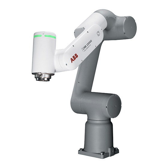
2.1 About CRB 15000 Introduction The CRB 15000 robot is a lightweight, flexible, agile 6-axis articulated, industrial robot, with a payload of 5 kg, designed specifically for manufacturing industries that use flexible robot-based automation, for example, the 3C industry. The robot has an open structure that is especially adapted for flexible use, and can communicate extensively with external systems. -
Page 36: Technical Data
These forces and torques are extreme values that are rarely encountered during operation. The values also never reach their maximum at the same time! Continues on next page Product manual - CRB 15000 3HAC077389-001 Revision: A © Copyright 2021 ABB. All rights reserved. - Page 37 Wall mounted robot has a work area for axis 1 that depends on payload and the positions of other axes. Simulation in RobotStudio is recom- mended. Continues on next page Product manual - CRB 15000 3HAC077389-001 Revision: A © Copyright 2021 ABB. All rights reserved.
- Page 38 The table shows the available protection types of the robot, with the corresponding protection class. Protection type Protection class Manipulator, protection type Standard IP54 Continues on next page Product manual - CRB 15000 3HAC077389-001 Revision: A © Copyright 2021 ABB. All rights reserved.
- Page 39 Axis Maximum joint torque 175.44 Nm 175.44 Nm 90.6 Nm 18.72 Nm 21.44 Nm 9.2 Nm Product manual - CRB 15000 3HAC077389-001 Revision: A © Copyright 2021 ABB. All rights reserved.
-
Page 40: Working Range
-90° -68° pos5 -507 -179 180° 22° pos6 -230.2 272.7 180° 85° pos7 -179 180° -158° pos8 198.1 287.6 180° -225° Continues on next page Product manual - CRB 15000 3HAC077389-001 Revision: A © Copyright 2021 ABB. All rights reserved. - Page 41 1 that depends on payload and the positions of other axes. Simulation in RobotStudio is recommended. Axis 2 ±180° Axis 3 -225°/+85° Axis 4 ±180° Axis 5 ±180° Axis 6 ±180° Product manual - CRB 15000 3HAC077389-001 Revision: A © Copyright 2021 ABB. All rights reserved.
-
Page 42: The Unit Is Sensitive To Esd
The mat must be grounded through a current-limiting resistor. • Use a dissipative table mat. The mat should provide a controlled discharge of static voltages and must be grounded. Product manual - CRB 15000 3HAC077389-001 Revision: A © Copyright 2021 ABB. All rights reserved. -
Page 43: Installation And Commissioning
Note If the CRB 15000 is connected to power, always make sure that the robot is connected to protective earth and a residual current device (RCD) before starting any installation work. For more information see: •... -
Page 44: Unpacking
It also contains information useful during later re-installation of the robot. Prerequisites for installation personnel Installation personnel working with an ABB product must: • Be trained by ABB and have the required knowledge of mechanical and electrical installation/maintenance/repair work. • Conform to all national and local codes. -
Page 45: Risk Of Tipping/Stability
0° Axis 3 +85° Axis 4 0° Axis 5 0° Axis 6 0° WARNING The robot is mechanically unstable if not secured to the foundation. Product manual - CRB 15000 3HAC077389-001 Revision: A © Copyright 2021 ABB. All rights reserved. -
Page 46: On-Site Installation
Introduction This procedure is a brief guide when installing the robot for the first time. Also see Pre-installation procedure on page First installation Use these procedures to install the CRB 15000. Action Note Transport the manipulator to its intended location. -
Page 47: Lifting The Robot
23/10.5/2.5 mm Steel Guide pins DIN6325, hardened steel Ø6x24 mm, 2 pcs Tightening torque 30 Nm ±10% Level surface requirements 0.1/500 mm Continues on next page Product manual - CRB 15000 3HAC077389-001 Revision: A © Copyright 2021 ABB. All rights reserved. - Page 48 This illustration shows the hole configuration used when securing the robot. + 0,012 6 H7 xx2000002366 Circular hole for locating pin Elongated hole for locating pin Continues on next page Product manual - CRB 15000 3HAC077389-001 Revision: A © Copyright 2021 ABB. All rights reserved.
- Page 49 Lifting and securing the robot Action Note CAUTION The CRB 15000 robot weighs 28 kg. A minim- um of two persons are required for lifting as well as securing the robot in order to avoid any damage, instability, and injury.
-
Page 50: Manually Releasing The Brakes
This procedure describes how to release the holding brakes using the brake release tool. Note The manipulator needs to be powered and motors in state Motors OFF. Continues on next page Product manual - CRB 15000 3HAC077389-001 Revision: A © Copyright 2021 ABB. All rights reserved. - Page 51 614. Put back the tool in its holder and store on specified location close to the robot. Continues on next page Product manual - CRB 15000 3HAC077389-001 Revision: A © Copyright 2021 ABB. All rights reserved.
- Page 52 Supply 0V on pin B and +48VDC on pin A. +48VDC (A) 0V (B) xx2100000124 Product manual - CRB 15000 3HAC077389-001 Revision: A © Copyright 2021 ABB. All rights reserved.
-
Page 53: Installation Of Brake Release Tool
Securing the brake release tool holder Securing with screws xx2100000403 Continues on next page Product manual - CRB 15000 3HAC077389-001 Revision: A © Copyright 2021 ABB. All rights reserved. - Page 54 3 Installation and commissioning 3.3.4 Installation of brake release tool Continued Securing with cable ties xx2100000404 Product manual - CRB 15000 3HAC077389-001 Revision: A © Copyright 2021 ABB. All rights reserved.
-
Page 55: Setting The System Parameters For A Suspended Or A Tilted Robot
If the robot is mounted on a wall (rotated around the x-axis), then the robot base frame and the system parameter Gravity Alpha must be redefined. The value of Gravity Alpha should then be ±π/2 (±1.570796). Continues on next page Product manual - CRB 15000 3HAC077389-001 Revision: A © Copyright 2021 ABB. All rights reserved. - Page 56 Examples of mounting angles tilted around the X axis (Gravity Alpha) The following illustration shows the IRB 120, but the same principle applies for all robots. 0° xx2100000297 xx2100000298 Continues on next page Product manual - CRB 15000 3HAC077389-001 Revision: A © Copyright 2021 ABB. All rights reserved.
- Page 57 Robot, in the topic Motion. The system parameters are described in Technical reference manual - System parameters. The system parameters are configured in RobotStudio or on the FlexPendant. Product manual - CRB 15000 3HAC077389-001 Revision: A © Copyright 2021 ABB. All rights reserved.
-
Page 58: Loads Fitted To The Robot, Stopping Time And Braking Distances
The performance of the motor brake depends on if there are any loads attached to the robot. See Product specification - Robot stopping distances according to ISO 10218-1. Product manual - CRB 15000 3HAC077389-001 Revision: A © Copyright 2021 ABB. All rights reserved. -
Page 59: Fitting Equipment On The Robot (Robot Dimensions)
• The brake release points on each axis must be accessible in the end application. Continues on next page Product manual - CRB 15000 3HAC077389-001 Revision: A © Copyright 2021 ABB. All rights reserved. - Page 60 7 x M6 xx2000002367 Fastener quality on tool flange Use screws with suitable length and tightening torque for your application. Screws with quality class 12.9 are recommended. Product manual - CRB 15000 3HAC077389-001 Revision: A © Copyright 2021 ABB. All rights reserved.
-
Page 61: First Test Run May Cause Injury Or Damage
Verify that all arm covers and paddings, if any, are properly secured to the robot. If maintenance or repair has been done, pay special attention to the function of the part that was maintained. Product manual - CRB 15000 3HAC077389-001 Revision: A © Copyright 2021 ABB. All rights reserved. -
Page 62: Electrical Connections
Robot cable Signal cable length Article number Hybrid floor cable 7 m 3HAC073212-002 Continues on next page Product manual - CRB 15000 3HAC077389-001 Revision: A © Copyright 2021 ABB. All rights reserved. - Page 63 Continued Bending radius for static floor cables The minimum bending radius is 10 times the cable diameter for static floor cables. xx1600002016 Diameter Diameter x10 Product manual - CRB 15000 3HAC077389-001 Revision: A © Copyright 2021 ABB. All rights reserved.
-
Page 64: Customer Connections On The Manipulator
Connectors at the base The R1.MP on the base is used for transferring DC bus, EtherCat and customer signals (CP/CS). xx2100000228 Continues on next page Product manual - CRB 15000 3HAC077389-001 Revision: A © Copyright 2021 ABB. All rights reserved. - Page 65 Note Always inspect the connector for dirt or damage before connecting it. Clean or replace any damaged parts. Continues on next page Product manual - CRB 15000 3HAC077389-001 Revision: A © Copyright 2021 ABB. All rights reserved.
- Page 66 (two pins for use, one pin is spare) M8x1 xx2100000220 M8 4 pin female, 200 mm 0.4 Nm Pin4 Pin2 wire, straight M10x0.75 Pin3 Pin1 M8x1 xx2100000219 Product manual - CRB 15000 3HAC077389-001 Revision: A © Copyright 2021 ABB. All rights reserved.
-
Page 67: Arm-Side Interface
The payload must be configured before configuring the arm-side interface. See Operating manual - OmniCore. The application ASI Setting on the FlexPendant must be open when using the buttons. Continues on next page Product manual - CRB 15000 3HAC077389-001 Revision: A © Copyright 2021 ABB. All rights reserved. - Page 68 On delivery, the light ring shows the states according to the following table: Color of the light ring State of the robot White Stand by Green Program running Yellow Programming in progress Error Continues on next page Product manual - CRB 15000 3HAC077389-001 Revision: A © Copyright 2021 ABB. All rights reserved.
- Page 69 Example of customized routine with the instruction MoveJ. PROC ASI_MoveRobot() TPWrite "The robot will move along path"; MoveJ Target_10,v1000,z100,tool0\WObj:=wobj0; MoveJ Target_20,v1000,z100,tool0\WObj:=wobj0; Continues on next page Product manual - CRB 15000 3HAC077389-001 Revision: A © Copyright 2021 ABB. All rights reserved.
- Page 70 The light will blink when a button is pressed on the arm-side interface. Note In RobotWare 7.2, the light ring configuration cannot be changed, only disabled. Product manual - CRB 15000 3HAC077389-001 Revision: A © Copyright 2021 ABB. All rights reserved.
-
Page 71: Using The Arm-Side Interface
The buttons on the arm-side interface can be used in both manual mode and automatic mode. Note The application ASI Setting on the FlexPendant must be open when using the buttons. Product manual - CRB 15000 3HAC077389-001 Revision: A © Copyright 2021 ABB. All rights reserved. -
Page 72: Configuring The Software
The configuration of emergency stops is stop category 1 and cannot be changed. Collision detection As default CRB 15000 will have collision detection active at stand still. It also has another stop ramp compared to other robots to be able to release clamping forces. -
Page 73: Lead-Through
Lead-through can also be enabled using the RAPID instruction SetLeadThrough, or a button on the arm side interface, see Arm-side interface on page 67. If the Continues on next page Product manual - CRB 15000 3HAC077389-001 Revision: A © Copyright 2021 ABB. All rights reserved. - Page 74 If the load is lighter than the defined load, the effect will be the same as if you are pulling the robot arm upwards. Note For CRB 15000 with SafeMove, some different behaviors apply, see CRB 15000 with SafeMove on page...
-
Page 75: Crb 15000 With Safemove
3 Installation and commissioning 3.6.3 CRB 15000 with SafeMove 3.6.3 CRB 15000 with SafeMove General For CRB 15000 with SafeMove, some different behaviors apply. For more information about SafeMove, see Application manual - SafeMove. Limitations Lead-through It is only possible to use lead-through if a Contact Application Tolerance (CAP) is configured in SafeMove. - Page 76 This page is intentionally left blank...
-
Page 77: Maintenance
Note If the CRB 15000 is connected to power, always make sure that the CRB 15000 is connected to protective earth and a residual current device (RCD) before starting any maintenance work. -
Page 78: Maintenance Schedule And Expected Component Life
4.2.1 Specification of maintenance intervals Introduction The intervals are specified in different ways depending on the type of maintenance activity to be carried out and the working conditions of the CRB 15000: • Calendar time: specified in months regardless of whether the system is running or not. -
Page 79: Maintenance Schedule
The inspection intervals do not specify the life of each component. Maintenance schedule Maintenance activities Reference Cleaning the CRB 15000 on page 86 Cleaning the robot Inspecting the robot on page 80 Inspecting the robot Inspecting the cable harness on... -
Page 80: Inspection Activities
Action Note Look for abnormal wear or contamination. Clean as necessary. Cleaning the CRB 15000 on page Check for loose hardware at robot arms, Tighten loose hardware at base (foundation base (foundation screws), and tool flange. screws tightening torque: 30 Nm ±10%) and tool flange, if any. - Page 81 M3x8 12.9 Gleitmo 603+Geo- met 500 Housing inner plate Hex socket head cap screw 1.4 Nm M3x8 12.9 Gleitmo 603+Geo- met 500 Continues on next page Product manual - CRB 15000 3HAC077389-001 Revision: A © Copyright 2021 ABB. All rights reserved.
- Page 82 M3x12 12.9 Gleitmo 603+Geo- met 500 Tool flange Hex socket head cap screw 0.45 Nm M3x12 12.9 Gleitmo 603+Geo- met 500 Base M10x35 8.8 30 Nm ±10% Product manual - CRB 15000 3HAC077389-001 Revision: A © Copyright 2021 ABB. All rights reserved.
-
Page 83: Inspecting The Cable Harness
Spare part number Cable harness, base socket 3HAC073202-001 Cable harness, joint 1 3HAC073204-001 Cable harness, joint 2 3HAC073205-001 Cable harness, joint 3 3HAC073207-001 Continues on next page Product manual - CRB 15000 3HAC077389-001 Revision: A © Copyright 2021 ABB. All rights reserved. - Page 84 Inspecting the cable harness Action Note CAUTION Turn off all supplies for electrical power to the robot, before starting the repair work. Continues on next page Product manual - CRB 15000 3HAC077389-001 Revision: A © Copyright 2021 ABB. All rights reserved.
- Page 85 CAUTION section Tightening torques to be inspected on page Be careful not to squeeze any cabling during the refitting procedure. Product manual - CRB 15000 3HAC077389-001 Revision: A © Copyright 2021 ABB. All rights reserved.
-
Page 86: Cleaning Activities
4.4.1 Cleaning the CRB 15000 General To secure high uptime it is important that the CRB 15000 is cleaned regularly. The frequency of cleaning depends on the environment in which the manipulator works. Different cleaning methods are allowed depending on the type of protection of the CRB 15000. -
Page 87: Testing Activities
• Look for damage to the magnet. Replace the tool if damaged. • See troubleshooting section Brake release tool does not work on page 614. Product manual - CRB 15000 3HAC077389-001 Revision: A © Copyright 2021 ABB. All rights reserved. -
Page 88: Testing The Functionality Of The Joint Electronics
Testing the joint electronics Action Note Turn off power to the controller and then turn the power on again. Verify that the robot starts as expected. Product manual - CRB 15000 3HAC077389-001 Revision: A © Copyright 2021 ABB. All rights reserved. -
Page 89: Repair
Repair activities not described in this chapter must only be carried out by ABB. Report replaced units Note When replacing a part on the CRB 15000, report to your local ABB the serial number, the article number, and the revision of both the replaced unit and the replacement unit. -
Page 90: General Procedures
Do not try to grind or polish the shaft surface to get rid of the defect. Continues on next page Product manual - CRB 15000 3HAC077389-001 Revision: A © Copyright 2021 ABB. All rights reserved. - Page 91 Mount the sealing correctly with a mounting tool. Never hammer directly on the sealing as this may result in leakage. xx2000000072 A Gap Continues on next page Product manual - CRB 15000 3HAC077389-001 Revision: A © Copyright 2021 ABB. All rights reserved.
- Page 92 If the flange surfaces are defective, the parts may not be used because leakage could occur. Clean the surfaces properly in accordance with the recommendations of ABB. Distribute the sealing compound evenly over the surface, preferably with a brush. Tighten the screws evenly when fastening the flange joint.
-
Page 93: Cable Harness
Required spare parts Note The spare part numbers that are listed in the table can be out of date. See the latest spare parts of the CRB 15000 via myABB Business Portal, www.abb.com/myABB. Continues on next page Product manual - CRB 15000 3HAC077389-001 Revision: A ©... - Page 94 • Axis 6: 0° xx2100000113 CAUTION Turn off all supplies for electrical power to the robot, before starting the repair work. Continues on next page Product manual - CRB 15000 3HAC077389-001 Revision: A © Copyright 2021 ABB. All rights reserved.
- Page 95 Laying down the robot Action Note CAUTION The CRB 15000 robot weighs 28 kg. A minimum of two persons are required for lifting as well as securing the robot in order to avoid any damage, instability, and injury. Loosen the robot from the foundation.
- Page 96 Disconnecting the base cabling Action Note Cut the cable ties. xx2100000424 Remove the functional and protective earth cables by removing the screw. xx2100000425 Continues on next page Product manual - CRB 15000 3HAC077389-001 Revision: A © Copyright 2021 ABB. All rights reserved.
- Page 97 D1.DC- from ground xx2100000405 Removing the base cabling Action Note Remove the attachment screws. xx2100000406 Pull out the cabling from the base. xx2100000407 Continues on next page Product manual - CRB 15000 3HAC077389-001 Revision: A © Copyright 2021 ABB. All rights reserved.
- Page 98 Secure the base connector with the attachment Hex socket head cap screw: M3x8 screws. 12.9 Gleitmo 603+Geomet 500 (4 pcs). Tightening torque: 0.8 Nm. xx2100000406 Continues on next page Product manual - CRB 15000 3HAC077389-001 Revision: A © Copyright 2021 ABB. All rights reserved.
- Page 99 Secure the cables for functional earth and protect- Hex socket head cap screw: M3x6 ive earth with a screw. (1 pcs). Tightening torque: 0.8 Nm. xx2100000425 Continues on next page Product manual - CRB 15000 3HAC077389-001 Revision: A © Copyright 2021 ABB. All rights reserved.
- Page 100 Wipe, lubricate and fit the o-ring to its groove. O-ring, nitrile rubber: 3HAB3772- Replace if damaged. Grease: 3HAC042536-001 (Shell Gadus S2) xx2000002016 Continues on next page Product manual - CRB 15000 3HAC077389-001 Revision: A © Copyright 2021 ABB. All rights reserved.
- Page 101 Lifting and securing the robot Action Note CAUTION The CRB 15000 robot weighs 28 kg. A minim- um of two persons are required for lifting as well as securing the robot in order to avoid any damage, instability, and injury.
- Page 102 Concluding procedure Action Note DANGER Make sure all safety requirements are met when performing the first test run. Product manual - CRB 15000 3HAC077389-001 Revision: A © Copyright 2021 ABB. All rights reserved.
-
Page 103: Replacing The Axis-1 Cabling
Required spare parts Note The spare part numbers that are listed in the table can be out of date. See the latest spare parts of the CRB 15000 via myABB Business Portal, www.abb.com/myABB. Continues on next page Product manual - CRB 15000 3HAC077389-001 Revision: A ©... - Page 104 3HAC061327-044 Lower arm, inner cover. 1 pcs / cover. Replace if damaged. O-ring 3HAC061327-047 Cover for axis 2/3 Replace if damaged. Continues on next page Product manual - CRB 15000 3HAC077389-001 Revision: A © Copyright 2021 ABB. All rights reserved.
- Page 105 Removing the lower arm covers Action Note CAUTION Make sure that all supplies for electrical power are turned off. Continues on next page Product manual - CRB 15000 3HAC077389-001 Revision: A © Copyright 2021 ABB. All rights reserved.
- Page 106 Remove the inner cover by removing the four screws. xx2000001930 Continues on next page Product manual - CRB 15000 3HAC077389-001 Revision: A © Copyright 2021 ABB. All rights reserved.
- Page 107 Remove the functional earth cable by removing the screw. xx2000001936 Cut the cable ties. xx2000001937 Snap loose and disconnect all connectors. xx2000001938 Continues on next page Product manual - CRB 15000 3HAC077389-001 Revision: A © Copyright 2021 ABB. All rights reserved.
- Page 108 Suggestion with lifting sling and an overhead crane: CAUTION The weight of the complete upper and lower arm together is 18 kg xx2100000294 Continues on next page Product manual - CRB 15000 3HAC077389-001 Revision: A © Copyright 2021 ABB. All rights reserved.
- Page 109 Remove the lower arm attachment screws. xx2000001940 Use two fully threaded attachment screws as re- moval tools to press the lower arm out of position. xx2000002151 Continues on next page Product manual - CRB 15000 3HAC077389-001 Revision: A © Copyright 2021 ABB. All rights reserved.
- Page 110 Removing the swing cover Action Note CAUTION Make sure that all supplies for electrical power are turned off. Remove the cover screws. xx2000001935 Continues on next page Product manual - CRB 15000 3HAC077389-001 Revision: A © Copyright 2021 ABB. All rights reserved.
- Page 111 The unit is sensitive to ESD. Before handling the unit read the safety information in section unit is sensitive to ESD on page Continues on next page Product manual - CRB 15000 3HAC077389-001 Revision: A © Copyright 2021 ABB. All rights reserved.
- Page 112 • D2.DC+ from DC+ • D2.DC- from ground • D2.X4 from X4 • D2.X2 from X2 • D2.X5 from X5 xx2000002013 Continues on next page Product manual - CRB 15000 3HAC077389-001 Revision: A © Copyright 2021 ABB. All rights reserved.
- Page 113 Use two screws as press out screws in the upcom- ing step, then dispose all screws. New screws are included in the spare part delivery of the joint unit. xx2000001943 Continues on next page Product manual - CRB 15000 3HAC077389-001 Revision: A © Copyright 2021 ABB. All rights reserved.
- Page 114 The connectors and the joint unit cables are sensitive to mechanical damage. Handle the as- sembly with care. xx2000001958 Remove the lifting aid and guide pins. xx2000001957 Continues on next page Product manual - CRB 15000 3HAC077389-001 Revision: A © Copyright 2021 ABB. All rights reserved.
- Page 115 Loosening the base and removing the base cover Action Note Loosen the base from the foundation by removing the attachment screws and washers. xx2000002006 Continues on next page Product manual - CRB 15000 3HAC077389-001 Revision: A © Copyright 2021 ABB. All rights reserved.
- Page 116 Remove the functional and protective earth cables by removing the screw. xx2000002011 Snap loose and disconnect the connectors: • J1.DC+ • J1.DC- • J1.CS • J1.CP xx2000002010 Continues on next page Product manual - CRB 15000 3HAC077389-001 Revision: A © Copyright 2021 ABB. All rights reserved.
- Page 117 If complete joint unit is to be replaced, the protection plate is not needed. xx2000002057 Cut the cable tie at the drive board. xx2000002058 Continues on next page Product manual - CRB 15000 3HAC077389-001 Revision: A © Copyright 2021 ABB. All rights reserved.
- Page 118 Disconnect the two connectors from the torque sensor board. • TQ.A • TQ.B xx2000002053 Remove the cable plate by removing the attach- ment screws. xx2000002049 Continues on next page Product manual - CRB 15000 3HAC077389-001 Revision: A © Copyright 2021 ABB. All rights reserved.
- Page 119 Orient the cable plate according to the figure. The circle on the cable plate should point towards the guide pin on the torque sensor. xx2000002051 Continues on next page Product manual - CRB 15000 3HAC077389-001 Revision: A © Copyright 2021 ABB. All rights reserved.
- Page 120 Hex socket head cap screw: M3x30 12.9 Gleitmo 603+Geomet 500 (2 pcs) Tightening torque: 0.45 Nm. xx2000002055 Continues on next page Product manual - CRB 15000 3HAC077389-001 Revision: A © Copyright 2021 ABB. All rights reserved.
- Page 121 Use the cable tie to pre-fix the cable by hand. xx2100000507 xx2100000508 Fit the protection plate to the drive board unit. Protection plate: 3HAC077790-001 xx2000002057 Continues on next page Product manual - CRB 15000 3HAC077389-001 Revision: A © Copyright 2021 ABB. All rights reserved.
- Page 122 Assembly direction for the cable tie is shown in Cable tie gun EVO7 the figure. Settiing for cable tie gun: 6.75. xx2000002058 xx2000002059 Remove the protection plate. xx2100000301 Continues on next page Product manual - CRB 15000 3HAC077389-001 Revision: A © Copyright 2021 ABB. All rights reserved.
- Page 123 Secure the cables for functional earth and protect- Hex socket head cap screw: M3x6 ive earth with a screw. (1 pcs). Tightening torque: 0.8 Nm. xx2000002011 Continues on next page Product manual - CRB 15000 3HAC077389-001 Revision: A © Copyright 2021 ABB. All rights reserved.
- Page 124 Wipe, lubricate and fit the o-ring to its groove. O-ring, nitrile rubber: 3HAB3772- Replace if damaged. Grease: 3HAC042536-001 (Shell Gadus S2) xx2000002016 Continues on next page Product manual - CRB 15000 3HAC077389-001 Revision: A © Copyright 2021 ABB. All rights reserved.
- Page 125 Attachment screws: M10x35 8.8 (4 foundation with the attachment screws and pcs). washers. Washers: 23/10.5/2.5 mm Steel (4 pcs). Tightening torque: 30 Nm ±10%. xx2000002006 Continues on next page Product manual - CRB 15000 3HAC077389-001 Revision: A © Copyright 2021 ABB. All rights reserved.
- Page 126 Hex socket head cap flange screw: M4x25 (16 pcs) Pre-tighten the screws crosswise firstly. xx2000001987 Torque tighten all screws crosswise. Tightening torque: 4.6 Nm. Continues on next page Product manual - CRB 15000 3HAC077389-001 Revision: A © Copyright 2021 ABB. All rights reserved.
- Page 127 Screws: M4x35 (4 pcs) The connectors and the joint unit cables are sensitive to mechanical damage. Handle the as- sembly with care. xx2000001957 Continues on next page Product manual - CRB 15000 3HAC077389-001 Revision: A © Copyright 2021 ABB. All rights reserved.
- Page 128 CAUTION xx2000001959 The connectors and the joint unit cables are sensitive to mechanical damage. Handle the as- sembly with care. xx2000001961 Continues on next page Product manual - CRB 15000 3HAC077389-001 Revision: A © Copyright 2021 ABB. All rights reserved.
- Page 129 Torque tighten all screws crosswise. Tightening torque: 4.3 Nm. Remove the lifting aid by removing the screws. xx2000001956 Clean pushed-out flange sealant, if any. Continues on next page Product manual - CRB 15000 3HAC077389-001 Revision: A © Copyright 2021 ABB. All rights reserved.
- Page 130 18 kg Lift the upper and lower arm assembly to mount- ing position and slide it onto the guide pins. xx2000001941 Continues on next page Product manual - CRB 15000 3HAC077389-001 Revision: A © Copyright 2021 ABB. All rights reserved.
- Page 131 The unit is sensitive to ESD. Before handling the unit read the safety information in section unit is sensitive to ESD on page Continues on next page Product manual - CRB 15000 3HAC077389-001 Revision: A © Copyright 2021 ABB. All rights reserved.
- Page 132 Secure the cables for functional earth and protect- Hex socket head cap screw: M3x6 ive earth with a screw. (1 pcs). Tightening torque: 0.8 Nm. xx2000001945 Continues on next page Product manual - CRB 15000 3HAC077389-001 Revision: A © Copyright 2021 ABB. All rights reserved.
- Page 133 Connect the connectors to each other and snap them to the cable holders. xx2000001938 Secure the cabling with cable ties. Cable ties (3 pcs) xx2000001937 Continues on next page Product manual - CRB 15000 3HAC077389-001 Revision: A © Copyright 2021 ABB. All rights reserved.
- Page 134 Refit the inner cover with four screws. Hex socket head cap screw: M3x8 12.9 Gleitmo 603+Geomet 500 (4 pcs) Tightening torque: 1.4 Nm. xx2000001930 Continues on next page Product manual - CRB 15000 3HAC077389-001 Revision: A © Copyright 2021 ABB. All rights reserved.
- Page 135 DR.X8 to the drive board. Orient the cover for proper arrangement of the brake release cable. xx2000001932 Continues on next page Product manual - CRB 15000 3HAC077389-001 Revision: A © Copyright 2021 ABB. All rights reserved.
- Page 136 Note Calibrate the joint unit torque sensor. Calibration on page 607 DANGER Make sure all safety requirements are met when performing the first test run. Product manual - CRB 15000 3HAC077389-001 Revision: A © Copyright 2021 ABB. All rights reserved.
-
Page 137: Replacing The Axis-2 Cabling
4 Replace the cabling. Required spare parts Note The spare part numbers that are listed in the table can be out of date. See the latest spare parts of the CRB 15000 via myABB Business Portal, www.abb.com/myABB. Spare part Article number... - Page 138 Removing the swing cover Action Note CAUTION Make sure that all supplies for electrical power are turned off. Continues on next page Product manual - CRB 15000 3HAC077389-001 Revision: A © Copyright 2021 ABB. All rights reserved.
- Page 139 Open the cover and cut the cable tie that holds the brake release cable. xx2000001931 Disconnect the brake release connector from the drive board. Remove the cover. xx2000001932 Continues on next page Product manual - CRB 15000 3HAC077389-001 Revision: A © Copyright 2021 ABB. All rights reserved.
- Page 140 Remove the functional and protective earth cables by removing the screw. xx2000001945 Snap loose and disconnect the connectors: • J2.DC+ • J2.DC- • J2.CS • J2.CP xx2000001944 Continues on next page Product manual - CRB 15000 3HAC077389-001 Revision: A © Copyright 2021 ABB. All rights reserved.
- Page 141 Note CAUTION Make sure that all supplies for electrical power are turned off. Remove the four lower arm cover screws. xx2000001929 Continues on next page Product manual - CRB 15000 3HAC077389-001 Revision: A © Copyright 2021 ABB. All rights reserved.
- Page 142 Disconnecting the cabling between the lower arm and the swing Action Note Remove the functional earth cable by removing the screw. xx2000001936 Continues on next page Product manual - CRB 15000 3HAC077389-001 Revision: A © Copyright 2021 ABB. All rights reserved.
- Page 143 Using the protection plate is important for protect- ing the drive board unit. If complete joint unit is to be replaced, the protection plate is not needed. xx2000002057 Continues on next page Product manual - CRB 15000 3HAC077389-001 Revision: A © Copyright 2021 ABB. All rights reserved.
- Page 144 Remove the cable support from the drive board by removing the attachment screws. xx2000002055 Disconnect the two connectors from the torque sensor board. • TQ.A • TQ.B xx2000002053 Continues on next page Product manual - CRB 15000 3HAC077389-001 Revision: A © Copyright 2021 ABB. All rights reserved.
- Page 145 Orient the cable plate according to the figure. The circle on the cable plate should point towards the guide pin on the torque sensor. xx2000002051 Continues on next page Product manual - CRB 15000 3HAC077389-001 Revision: A © Copyright 2021 ABB. All rights reserved.
- Page 146 Hex socket head cap screw: M3x30 12.9 Gleitmo 603+Geomet 500 (2 pcs) Tightening torque: 0.45 Nm. xx2000002055 Continues on next page Product manual - CRB 15000 3HAC077389-001 Revision: A © Copyright 2021 ABB. All rights reserved.
- Page 147 Use the cable tie to pre-fix the cable by hand. xx2100000507 xx2100000508 Fit the protection plate to the drive board unit. Protection plate: 3HAC077790-001 xx2000002057 Continues on next page Product manual - CRB 15000 3HAC077389-001 Revision: A © Copyright 2021 ABB. All rights reserved.
- Page 148 Assembly direction for the cable tie is shown in Cable tie gun EVO7 the figure. Settiing for cable tie gun: 6.75. xx2000002058 xx2000002059 Remove the protection plate. xx2100000301 Continues on next page Product manual - CRB 15000 3HAC077389-001 Revision: A © Copyright 2021 ABB. All rights reserved.
- Page 149 Connect the functional earth cable with the screw. Hex socket head cap screw: M3x8 12.9 Gleitmo 603+Geomet 500 (1 pcs). Tightening torque: 0.8 Nm xx2000001936 Continues on next page Product manual - CRB 15000 3HAC077389-001 Revision: A © Copyright 2021 ABB. All rights reserved.
- Page 150 Hex socket head cap screw: M3x16 12.9 Gleitmo 603+Geomet 500 Secure the cover with four screws. (Black Oxide) (4 pcs) Tightening torque: 0.45 Nm. xx2000001929 Continues on next page Product manual - CRB 15000 3HAC077389-001 Revision: A © Copyright 2021 ABB. All rights reserved.
- Page 151 Secure the cables for functional earth and protect- Hex socket head cap screw: M3x6 ive earth with a screw. (1 pcs). Tightening torque: 0.8 Nm. xx2000001945 Continues on next page Product manual - CRB 15000 3HAC077389-001 Revision: A © Copyright 2021 ABB. All rights reserved.
- Page 152 DR.X8 to the drive board. Orient the cover for proper arrangement of the brake release cable. xx2000001932 Continues on next page Product manual - CRB 15000 3HAC077389-001 Revision: A © Copyright 2021 ABB. All rights reserved.
- Page 153 12.9 Gleitmo 603+Geomet 500 (4 pcs) Tightening torque: 0.45 Nm xx2000001935 Concluding procedure Action Note DANGER Make sure all safety requirements are met when performing the first test run. Product manual - CRB 15000 3HAC077389-001 Revision: A © Copyright 2021 ABB. All rights reserved.
-
Page 154: Replacing The Axis-3 Cabling
1 Remove the lower arm covers. 2 Remove the housing cover. 3 Disconnect the joint-3 cabling. 4 Replace the cabling. Continues on next page Product manual - CRB 15000 3HAC077389-001 Revision: A © Copyright 2021 ABB. All rights reserved. - Page 155 5.3.4 Replacing the axis-3 cabling Continued Required spare parts Note The spare part numbers that are listed in the table can be out of date. See the latest spare parts of the CRB 15000 via myABB Business Portal, www.abb.com/myABB. Spare part Article number Note...
- Page 156 Remove the cover by inserting a small flat screwdriver to snap open the locks at each end of the cover. xx2100000267 Continues on next page Product manual - CRB 15000 3HAC077389-001 Revision: A © Copyright 2021 ABB. All rights reserved.
- Page 157 Disconnecting the upper arm cabling Action Note Cut the cable ties. xx2000001937 Snap loose and disconnect all connectors. xx2000001938 Continues on next page Product manual - CRB 15000 3HAC077389-001 Revision: A © Copyright 2021 ABB. All rights reserved.
- Page 158 Open the cover with care to avoid damage to the cabling or the connector(s). Do not leave the cover in location without being secured with the attachment screws. Continues on next page Product manual - CRB 15000 3HAC077389-001 Revision: A © Copyright 2021 ABB. All rights reserved.
- Page 159 Disconnect the brake release connector from the drive board. Remove the cover. xx2000002023 Disconnecting the axis-3 joint unit cabling Action Note Cut the cable ties. xx2000002066 Continues on next page Product manual - CRB 15000 3HAC077389-001 Revision: A © Copyright 2021 ABB. All rights reserved.
- Page 160 The unit is sensitive to ESD. Before handling the unit read the safety information in section unit is sensitive to ESD on page Continues on next page Product manual - CRB 15000 3HAC077389-001 Revision: A © Copyright 2021 ABB. All rights reserved.
- Page 161 Cut the cable tie at the drive board. xx2000002058 Remove the protection plate. xx2100000301 Continues on next page Product manual - CRB 15000 3HAC077389-001 Revision: A © Copyright 2021 ABB. All rights reserved.
- Page 162 The unit is sensitive to ESD. Before handling the unit read the safety information in section unit is sensitive to ESD on page Continues on next page Product manual - CRB 15000 3HAC077389-001 Revision: A © Copyright 2021 ABB. All rights reserved.
- Page 163 Tightening torque: 0.45 Nm. xx2000002049 Connect the two connectors to the torque sensor board. • TQ.A to CH1/A • TQ.B to CH2/B xx2000002053 Continues on next page Product manual - CRB 15000 3HAC077389-001 Revision: A © Copyright 2021 ABB. All rights reserved.
- Page 164 Use the cable tie to pre-fix the cable by hand. xx2100000507 xx2100000508 Continues on next page Product manual - CRB 15000 3HAC077389-001 Revision: A © Copyright 2021 ABB. All rights reserved.
- Page 165 Assembly direction for the cable tie is shown in Cable tie gun EVO7 the figure. Settiing for cable tie gun: 6.75. xx2000002058 xx2000002059 Continues on next page Product manual - CRB 15000 3HAC077389-001 Revision: A © Copyright 2021 ABB. All rights reserved.
- Page 166 • J4.DC+ to J4/5.DC+ • J4.DC- to J4/5.DC- • J4.CS to J4/5.CS • J4.CP to J4/5.CP xx2000002067 Continues on next page Product manual - CRB 15000 3HAC077389-001 Revision: A © Copyright 2021 ABB. All rights reserved.
- Page 167 Cable ties (3 pcs) xx2000002066 Refitting the housing cover Action Note Fit the o-ring to its groove. O-ring: 3HAC061327-047 Replace if damaged. xx2000001962 Continues on next page Product manual - CRB 15000 3HAC077389-001 Revision: A © Copyright 2021 ABB. All rights reserved.
- Page 168 Refit the cover with the four screws. Hex socket head cap screw: M3x30 12.9 Gleitmo 603+Geomet 500 (4 pcs) Tightening torque: 0.45 Nm xx2000002021 Continues on next page Product manual - CRB 15000 3HAC077389-001 Revision: A © Copyright 2021 ABB. All rights reserved.
- Page 169 Connecting the upper arm cabling Action Note Connect the connectors to each other and snap them to the cable holders. xx2000001938 Continues on next page Product manual - CRB 15000 3HAC077389-001 Revision: A © Copyright 2021 ABB. All rights reserved.
- Page 170 Wipe, lubricate and fit the o-ring to its groove. O-ring: 3HAC061327-044 Replace if damaged. Grease: 3HAC042536-001 (Shell Gadus S2) xx2000001955 xx2000001954 Continues on next page Product manual - CRB 15000 3HAC077389-001 Revision: A © Copyright 2021 ABB. All rights reserved.
- Page 171 (Black Oxide) (4 pcs) Tightening torque: 0.45 Nm. xx2000001929 Concluding procedure Action Note DANGER Make sure all safety requirements are met when performing the first test run. Product manual - CRB 15000 3HAC077389-001 Revision: A © Copyright 2021 ABB. All rights reserved.
-
Page 172: Replacing The Axis-4 Cabling
Required spare parts Note The spare part numbers that are listed in the table can be out of date. See the latest spare parts of the CRB 15000 via myABB Business Portal, www.abb.com/myABB. Continues on next page Product manual - CRB 15000 3HAC077389-001 Revision: A ©... - Page 173 Axis 5: 0° • Axis 6: 0° CAUTION Turn off all supplies for electrical power to the robot, before starting the repair work. Continues on next page Product manual - CRB 15000 3HAC077389-001 Revision: A © Copyright 2021 ABB. All rights reserved.
- Page 174 Open the cover and cut the cable tie that holds the brake release cable. xx2000002022 Disconnect the brake release connector from the drive board. Remove the cover. xx2000002023 Continues on next page Product manual - CRB 15000 3HAC077389-001 Revision: A © Copyright 2021 ABB. All rights reserved.
- Page 175 Remove the functional and protective earth cables by removing the screw. xx2000001945 Snap loose and disconnect the connectors: • J4/5.DC+ • J4/5.DC- • J4/5.CS • J4/5.CP xx2000002067 Continues on next page Product manual - CRB 15000 3HAC077389-001 Revision: A © Copyright 2021 ABB. All rights reserved.
- Page 176 Opening the housing top cover Action Note Remove the cover by removing the four screws. xx2000002075 Remove the inner plate by removing the screws. xx2000002076 Continues on next page Product manual - CRB 15000 3HAC077389-001 Revision: A © Copyright 2021 ABB. All rights reserved.
- Page 177 Pull out the cabling carefully from the housing. xx2100000344 Removing the axis-4 cover Action Note Remove the cover screws. xx2000002083 Continues on next page Product manual - CRB 15000 3HAC077389-001 Revision: A © Copyright 2021 ABB. All rights reserved.
- Page 178 Disconnect the brake release connector from the Tweezers drive board. Remove the cover. xx2000002085 Disconnecting the axis-5 connectors Action Note Cut the cable ties. xx2000002086 Continues on next page Product manual - CRB 15000 3HAC077389-001 Revision: A © Copyright 2021 ABB. All rights reserved.
- Page 179 The unit is sensitive to ESD. Before handling the unit read the safety information in section unit is sensitive to ESD on page Continues on next page Product manual - CRB 15000 3HAC077389-001 Revision: A © Copyright 2021 ABB. All rights reserved.
- Page 180 Cut the cable tie at the drive board. xx2000002058 Remove the protection plate. xx2100000301 Continues on next page Product manual - CRB 15000 3HAC077389-001 Revision: A © Copyright 2021 ABB. All rights reserved.
- Page 181 The unit is sensitive to ESD. Before handling the unit read the safety information in section unit is sensitive to ESD on page Continues on next page Product manual - CRB 15000 3HAC077389-001 Revision: A © Copyright 2021 ABB. All rights reserved.
- Page 182 Tightening torque: 0.45 Nm. xx2000002049 Connect the two connectors to the torque sensor board. • TQ.A to CH1/A • TQ.B to CH2/B xx2000002053 Continues on next page Product manual - CRB 15000 3HAC077389-001 Revision: A © Copyright 2021 ABB. All rights reserved.
- Page 183 Use the cable tie to pre-fix the cable by hand. xx2100000507 xx2100000508 Continues on next page Product manual - CRB 15000 3HAC077389-001 Revision: A © Copyright 2021 ABB. All rights reserved.
- Page 184 Assembly direction for the cable tie is shown in Cable tie gun EVO7 the figure. Settiing for cable tie gun: 6.75. xx2000002058 xx2000002059 Continues on next page Product manual - CRB 15000 3HAC077389-001 Revision: A © Copyright 2021 ABB. All rights reserved.
- Page 185 Refit the cable bracket with the two screws. Hex socket head cap screw: M3x8 12.9 Gleitmo 603+Geomet 500 (4 pcs). Tightening torque: 0.8 Nm xx2000002078 Continues on next page Product manual - CRB 15000 3HAC077389-001 Revision: A © Copyright 2021 ABB. All rights reserved.
- Page 186 • J4/5.DC+ to J5/6.DC+ • J4/5.DC- to J5/6.DC- • J4/5.CS to J5/6.CS • J4/5.CP to J5/6.CP xx2000002089 Continues on next page Product manual - CRB 15000 3HAC077389-001 Revision: A © Copyright 2021 ABB. All rights reserved.
- Page 187 Cable ties (3 pcs) xx2000002086 xx2000002124 Refitting the axis-4 cover Action Note Fit the o-ring to its groove. O-ring: 3HAC061327-051 Replace if damaged. xx2000002092 Continues on next page Product manual - CRB 15000 3HAC077389-001 Revision: A © Copyright 2021 ABB. All rights reserved.
- Page 188 Tightening torque: 0.45 Nm xx2000002083 Closing the housing top cover Action Note Check the inner plate gasket. Gasket: 3HAC075056-001 Replace if damaged. xx2000002095 Continues on next page Product manual - CRB 15000 3HAC077389-001 Revision: A © Copyright 2021 ABB. All rights reserved.
- Page 189 Note Reconnect the connectors to the drive board. • D3/4.DC+ to DC+ • D3/4.DC- to Ground • D3/4.X2 to X2 xx2000002120 Continues on next page Product manual - CRB 15000 3HAC077389-001 Revision: A © Copyright 2021 ABB. All rights reserved.
- Page 190 (1 pcs). Tightening torque: 0.8 Nm. xx2000001945 Secure the cabling with cable ties. Cable ties (3 pcs) xx2000002066 Continues on next page Product manual - CRB 15000 3HAC077389-001 Revision: A © Copyright 2021 ABB. All rights reserved.
- Page 191 Orient the cover for proper arrangement of the brake release cable. xx2000002023 Secure the brake release cable with a cable tie. Cable ties xx2000002022 Continues on next page Product manual - CRB 15000 3HAC077389-001 Revision: A © Copyright 2021 ABB. All rights reserved.
- Page 192 12.9 Gleitmo 603+Geomet 500 (4 pcs) Tightening torque: 0.45 Nm xx2000002021 Concluding procedure Action Note DANGER Make sure all safety requirements are met when performing the first test run. Product manual - CRB 15000 3HAC077389-001 Revision: A © Copyright 2021 ABB. All rights reserved.
-
Page 193: Replacing The Axis-5 Cabling
3 Pull out the joint-5 cabling from the tubular. 4 Remove the axis-5 cover. 5 Disconnect the joint-5 cabling. 6 Replace the cabling. Continues on next page Product manual - CRB 15000 3HAC077389-001 Revision: A © Copyright 2021 ABB. All rights reserved. - Page 194 5.3.6 Replacing the axis-5 cabling Continued Required spare parts Note The spare part numbers that are listed in the table can be out of date. See the latest spare parts of the CRB 15000 via myABB Business Portal, www.abb.com/myABB. Spare part Article number Note...
- Page 195 Open the cover with care to avoid damage to the cabling or the connector(s). Do not leave the cover in location without being secured with the attachment screws. Continues on next page Product manual - CRB 15000 3HAC077389-001 Revision: A © Copyright 2021 ABB. All rights reserved.
- Page 196 Remove the cover. xx2000002085 Separating the cabling between the tubular and the tilt Action Note Cut the cable ties, if needed. xx2000002124 xx2000002086 Continues on next page Product manual - CRB 15000 3HAC077389-001 Revision: A © Copyright 2021 ABB. All rights reserved.
- Page 197 • D3/4.X2 • D3/4.DC- • D3/4.DC+ Use tweezers, if needed. xx2000002125 Pull out the cabling carefully from the tubular. xx2000002126 Continues on next page Product manual - CRB 15000 3HAC077389-001 Revision: A © Copyright 2021 ABB. All rights reserved.
- Page 198 Open the cover and cut the cable tie that holds the brake release cable. xx2000002133 Disconnect the brake release connector from the drive board. Remove the cover. xx2000002134 Continues on next page Product manual - CRB 15000 3HAC077389-001 Revision: A © Copyright 2021 ABB. All rights reserved.
- Page 199 Disconnect the connectors from the drive board. Tweezers • D4/5.X1 • D5.DC+ • D5.DC- • D4/5.X4 • D5.X2 • D4/5.X5 Use tweezers, if needed. xx2000002138 Continues on next page Product manual - CRB 15000 3HAC077389-001 Revision: A © Copyright 2021 ABB. All rights reserved.
- Page 200 Cut the cable tie at the drive board. xx2000002058 Remove the protection plate. xx2100000301 Continues on next page Product manual - CRB 15000 3HAC077389-001 Revision: A © Copyright 2021 ABB. All rights reserved.
- Page 201 The unit is sensitive to ESD. Before handling the unit read the safety information in section unit is sensitive to ESD on page Continues on next page Product manual - CRB 15000 3HAC077389-001 Revision: A © Copyright 2021 ABB. All rights reserved.
- Page 202 Tightening torque: 0.45 Nm. xx2000002049 Connect the two connectors to the torque sensor board. • TQ.A to CH1/A • TQ.B to CH2/B xx2000002053 Continues on next page Product manual - CRB 15000 3HAC077389-001 Revision: A © Copyright 2021 ABB. All rights reserved.
- Page 203 Use the cable tie to pre-fix the cable by hand. xx2100000507 xx2100000508 Continues on next page Product manual - CRB 15000 3HAC077389-001 Revision: A © Copyright 2021 ABB. All rights reserved.
- Page 204 Assembly direction for the cable tie is shown in Cable tie gun EVO7 the figure. Settiing for cable tie gun: 6.75. xx2000002058 xx2000002059 Continues on next page Product manual - CRB 15000 3HAC077389-001 Revision: A © Copyright 2021 ABB. All rights reserved.
- Page 205 • J5/6.DC+ to J6.DC+ • J5/6.DC- to J6.DC- • J5/6.CS to J6.CS • J5/6.CP to J6.CP xx2000002137 Continues on next page Product manual - CRB 15000 3HAC077389-001 Revision: A © Copyright 2021 ABB. All rights reserved.
- Page 206 Cable ties (3 pcs) xx2000002135 Refitting the axis-5 cover Action Note Fit the o-ring to its groove. O-ring: 3HAC061327-051 Replace if damaged. xx2000001962 Continues on next page Product manual - CRB 15000 3HAC077389-001 Revision: A © Copyright 2021 ABB. All rights reserved.
- Page 207 12.9 Gleitmo 603+Geomet 500 (4 pcs) Tightening torque: 0.45 Nm xx2000002132 Connecting the tilt cabling Action Note Insert the cabling into the tubular. xx2000002148 Continues on next page Product manual - CRB 15000 3HAC077389-001 Revision: A © Copyright 2021 ABB. All rights reserved.
- Page 208 Secure the cables for functional earth and protect- Hex socket head cap screw: M3x6 ive earth with a screw. (1 pcs). Tightening torque: 0.8 Nm. xx2000002087 Continues on next page Product manual - CRB 15000 3HAC077389-001 Revision: A © Copyright 2021 ABB. All rights reserved.
- Page 209 Place the cover at mounting position and recon- Tweezers nect the brake release connector DR.X8 to the drive board. xx2000002085 Continues on next page Product manual - CRB 15000 3HAC077389-001 Revision: A © Copyright 2021 ABB. All rights reserved.
- Page 210 Note Wipe, lubricate and fit the o-ring to its groove. O-ring: 3HAC061327-043 Replace if damaged. Grease: 3HAC042536-001 (Shell Gadus S2) xx2000002149 Continues on next page Product manual - CRB 15000 3HAC077389-001 Revision: A © Copyright 2021 ABB. All rights reserved.
- Page 211 Tightening torque: 1.6 Nm. xx2000002123 Concluding procedure Action Note DANGER Make sure all safety requirements are met when performing the first test run. Product manual - CRB 15000 3HAC077389-001 Revision: A © Copyright 2021 ABB. All rights reserved.
-
Page 212: Replacing The Axis-6 Cabling
4 Replace the cabling. Required spare parts Note The spare part numbers that are listed in the table can be out of date. See the latest spare parts of the CRB 15000 via myABB Business Portal, www.abb.com/myABB. Spare part Article number... - Page 213 Removing the arm-side interface Action Note CAUTION Make sure that all supplies for electrical power are turned off. Continues on next page Product manual - CRB 15000 3HAC077389-001 Revision: A © Copyright 2021 ABB. All rights reserved.
- Page 214 • ASI.DC+ • ASI.DC- • ASI.X1 xx2100000335 Removing the tool flange Action Note Remove the tool flange screws and washers. xx2000002155 Continues on next page Product manual - CRB 15000 3HAC077389-001 Revision: A © Copyright 2021 ABB. All rights reserved.
- Page 215 Cut the cable ties. xx2000002157 Disconnect the CP/CS connectors from the drive board and remove the tool flange. xx2000002158 Continues on next page Product manual - CRB 15000 3HAC077389-001 Revision: A © Copyright 2021 ABB. All rights reserved.
- Page 216 Remove the functional and protective earth cables by removing the screw. xx2000002162 Snap loose and disconnect the connectors: • J7.CS • J7.CP xx2000002163 Continues on next page Product manual - CRB 15000 3HAC077389-001 Revision: A © Copyright 2021 ABB. All rights reserved.
- Page 217 If complete joint unit is to be replaced, the protection plate is not needed. xx2000002057 Cut the cable tie at the drive board. xx2000002058 Continues on next page Product manual - CRB 15000 3HAC077389-001 Revision: A © Copyright 2021 ABB. All rights reserved.
- Page 218 Disconnect the two connectors from the torque sensor board. • TQ.A • TQ.B xx2000002053 Remove the cable plate by removing the attach- ment screws. xx2000002049 Continues on next page Product manual - CRB 15000 3HAC077389-001 Revision: A © Copyright 2021 ABB. All rights reserved.
- Page 219 Orient the cable plate according to the figure. The circle on the cable plate should point towards the guide pin on the torque sensor. xx2000002051 Continues on next page Product manual - CRB 15000 3HAC077389-001 Revision: A © Copyright 2021 ABB. All rights reserved.
- Page 220 Hex socket head cap screw: M3x30 12.9 Gleitmo 603+Geomet 500 (2 pcs) Tightening torque: 0.45 Nm. xx2000002055 Continues on next page Product manual - CRB 15000 3HAC077389-001 Revision: A © Copyright 2021 ABB. All rights reserved.
- Page 221 Use the cable tie to pre-fix the cable by hand. xx2100000507 xx2100000508 Fit the protection plate to the drive board unit. Protection plate: 3HAC077790-001 xx2000002057 Continues on next page Product manual - CRB 15000 3HAC077389-001 Revision: A © Copyright 2021 ABB. All rights reserved.
- Page 222 Assembly direction for the cable tie is shown in Cable tie gun EVO7 the figure. Settiing for cable tie gun: 6.75. xx2000002058 xx2000002059 Remove the protection plate. xx2100000301 Continues on next page Product manual - CRB 15000 3HAC077389-001 Revision: A © Copyright 2021 ABB. All rights reserved.
- Page 223 (1 pcs). Tightening torque: 0.8 Nm. xx2000002162 Secure the cabling with cable ties. Cable ties (3 pcs) xx2000002161 Continues on next page Product manual - CRB 15000 3HAC077389-001 Revision: A © Copyright 2021 ABB. All rights reserved.
- Page 224 Refit the arm-side interface with four screws. Hex socket head cap screw: M3x30 12.9 Gleitmo 603+Geomet 500 (4 pcs) Tightening torque: 0.45 Nm xx2000002550 Continues on next page Product manual - CRB 15000 3HAC077389-001 Revision: A © Copyright 2021 ABB. All rights reserved.
- Page 225 Replace if damaged. Grease: 3HAC042536-001 (Shell Gadus S2) xx2000002197 Place the tool flange at mounting position and reconnect the CP/CS connectors. xx2000002158 Continues on next page Product manual - CRB 15000 3HAC077389-001 Revision: A © Copyright 2021 ABB. All rights reserved.
- Page 226 Spring washer: 7x3.2x0.6 Steel (10 pcs) Tightening torque: 1.8 Nm. xx2000002155 Concluding procedure Action Note DANGER Make sure all safety requirements are met when performing the first test run. Product manual - CRB 15000 3HAC077389-001 Revision: A © Copyright 2021 ABB. All rights reserved.
-
Page 227: Replacing The Axis-5 To Axis-6 Transition Cabling
The replacement procedure is identical to replacing the axis-5 joint unit. Follow procedure Replacing the axis-5 joint unit and the axis-5 to axis-6 transition cabling on page 542. Product manual - CRB 15000 3HAC077389-001 Revision: A © Copyright 2021 ABB. All rights reserved. -
Page 228: Replacing The Brake Release Unit
4 Replace the brake release unit. Axis-2/-3/-4/-5 brake release unit 1 Open the joint unit cover. 2 Replace the brake release unit. Continues on next page Product manual - CRB 15000 3HAC077389-001 Revision: A © Copyright 2021 ABB. All rights reserved. - Page 229 5.3.9 Replacing the brake release unit Continued Required spare parts Note The spare part numbers that are listed in the table can be out of date. See the latest spare parts of the CRB 15000 via myABB Business Portal, www.abb.com/myABB. Spare part Article number Note...
- Page 230 Laying down the robot Action Note CAUTION The CRB 15000 robot weighs 28 kg. A minimum of two persons are required for lifting as well as securing the robot in order to avoid any damage, instability, and injury. Continues on next page...
- Page 231 Remove the bottom cover by removing the attach- ment screws. xx2000002007 Removing the brake release unit Action Note Cut the cable tie. xx2100000410 Continues on next page Product manual - CRB 15000 3HAC077389-001 Revision: A © Copyright 2021 ABB. All rights reserved.
- Page 232 Remove the brake release unit by removing the screws. xx2100000413 Remove the brake release cover by removing the two screws. xx2100000416 Remove the brake release board. xx2100000418 Continues on next page Product manual - CRB 15000 3HAC077389-001 Revision: A © Copyright 2021 ABB. All rights reserved.
- Page 233 Harmonic Grease 4B No.2 Used to lubricate the seals. xx2100000419 If not already fitted, place the sheet metal inside the cover. xx2100000420 Continues on next page Product manual - CRB 15000 3HAC077389-001 Revision: A © Copyright 2021 ABB. All rights reserved.
- Page 234 Fit the brake release cover and secure with two Screws: M2x6 12.9 Gleitmo 605 (2 screws. pcs) Tightening torque: 0.2 Nm. xx2100000416 Continues on next page Product manual - CRB 15000 3HAC077389-001 Revision: A © Copyright 2021 ABB. All rights reserved.
- Page 235 Screws: M3x5 12.9 Gleitmo 603+Geomet 500 (4 pcs) Tightening torque: 0.45 Nm. xx2100000413 Reconnect the brake release connector DR.X8 to the drive board. xx2100000411 Continues on next page Product manual - CRB 15000 3HAC077389-001 Revision: A © Copyright 2021 ABB. All rights reserved.
- Page 236 Wipe, lubricate and fit the o-ring to its groove. O-ring, nitrile rubber: 3HAB3772- Replace if damaged. Grease: 3HAC042536-001 (Shell Gadus S2) xx2000002016 Continues on next page Product manual - CRB 15000 3HAC077389-001 Revision: A © Copyright 2021 ABB. All rights reserved.
- Page 237 Lifting and securing the robot Action Note CAUTION The CRB 15000 robot weighs 28 kg. A minim- um of two persons are required for lifting as well as securing the robot in order to avoid any damage, instability, and injury.
- Page 238 Open the cover with care to avoid damage to the cabling or the connector(s). Do not leave the cover in location without being secured with the attachment screws. Continues on next page Product manual - CRB 15000 3HAC077389-001 Revision: A © Copyright 2021 ABB. All rights reserved.
- Page 239 Disconnect the brake release connector from the drive board. Remove the cover. xx2000001932 Removing the brake release unit Action Note Cut the cable tie. xx2100000096 Continues on next page Product manual - CRB 15000 3HAC077389-001 Revision: A © Copyright 2021 ABB. All rights reserved.
- Page 240 Remove the brake release cover by removing the two screws. xx2100000095 Disconnect the brake release cable from the board. xx2100000094 Remove the brake release board. xx2100000093 Continues on next page Product manual - CRB 15000 3HAC077389-001 Revision: A © Copyright 2021 ABB. All rights reserved.
- Page 241 Fit the brake release board to the sheet metal. xx2100000093 Connect the brake release cable to the board. xx2100000094 Continues on next page Product manual - CRB 15000 3HAC077389-001 Revision: A © Copyright 2021 ABB. All rights reserved.
- Page 242 Secure the cable with a cable tie. xx2100000096 Closing the joint unit cover Action Note Fit the o-ring to its groove. O-ring: 3HAC061327-047 Replace if damaged. xx2000001962 Continues on next page Product manual - CRB 15000 3HAC077389-001 Revision: A © Copyright 2021 ABB. All rights reserved.
- Page 243 12.9 Gleitmo 603+Geomet 500 (4 pcs) Tightening torque: 0.45 Nm xx2000001935 Concluding procedure Action Note DANGER Make sure all safety requirements are met when performing the first test run. Product manual - CRB 15000 3HAC077389-001 Revision: A © Copyright 2021 ABB. All rights reserved.
-
Page 244: Upper And Lower Arms
Required spare parts Note The spare part numbers that are listed in the table can be out of date. See the latest spare parts of the CRB 15000 via myABB Business Portal, www.abb.com/myABB. Continues on next page Product manual - CRB 15000 3HAC077389-001 Revision: A ©... - Page 245 Removing the lower arm covers Action Note CAUTION Make sure that all supplies for electrical power are turned off. Continues on next page Product manual - CRB 15000 3HAC077389-001 Revision: A © Copyright 2021 ABB. All rights reserved.
- Page 246 Remove the inner covers by removing the screws. xx2000001947 xx2000001930 Continues on next page Product manual - CRB 15000 3HAC077389-001 Revision: A © Copyright 2021 ABB. All rights reserved.
- Page 247 Loosening the cabling between the lower and upper arm Action Note Remove the functional earth cable by removing the screw. xx2000001964 Continues on next page Product manual - CRB 15000 3HAC077389-001 Revision: A © Copyright 2021 ABB. All rights reserved.
- Page 248 Fit two guide pins to the axis-3 joint unit. Guide pin, M4x120: 3HAC077786- Always use guide pins in pairs. xx2000001968 Continues on next page Product manual - CRB 15000 3HAC077389-001 Revision: A © Copyright 2021 ABB. All rights reserved.
- Page 249 Place the upper arm on a workbench. xx2000001970 Removing the lower arm Action Note Secure the weight of the lower arm. Continues on next page Product manual - CRB 15000 3HAC077389-001 Revision: A © Copyright 2021 ABB. All rights reserved.
- Page 250 Remove the lower arm attachment screws. xx2000001940 Use two fully threaded attachment screws as re- moval tools to press the lower arm out of position. xx2000002151 Continues on next page Product manual - CRB 15000 3HAC077389-001 Revision: A © Copyright 2021 ABB. All rights reserved.
- Page 251 Apply flange sealant to the corner of the lower Flange sealant: Loctite 574 arm mounting surface, as pointed out in the figure. xx2000001963 Continues on next page Product manual - CRB 15000 3HAC077389-001 Revision: A © Copyright 2021 ABB. All rights reserved.
- Page 252 Hex socket head cap flange screw: two screws. M4x25 (16 pcs) xx2000001951 Torque tighten all screws crosswise. Tightening torque: 4.6 Nm. Continues on next page Product manual - CRB 15000 3HAC077389-001 Revision: A © Copyright 2021 ABB. All rights reserved.
- Page 253 Secure the upper arm to the lower arm with all Hex socket head cap flange screw: attachment screws but two. M4x25 (16 pcs) Pre-tighten the screws crosswise firstly. xx2000001969 Continues on next page Product manual - CRB 15000 3HAC077389-001 Revision: A © Copyright 2021 ABB. All rights reserved.
- Page 254 Connecting the cabling between the lower arm and swing Action Note Connect the connectors to each other and snap them to the cable holders. xx2000001938 Continues on next page Product manual - CRB 15000 3HAC077389-001 Revision: A © Copyright 2021 ABB. All rights reserved.
- Page 255 Fastening the cabling between the lower and upper arm Action Note Secure the cabling with the cable tie. Cable ties xx2000001965 Continues on next page Product manual - CRB 15000 3HAC077389-001 Revision: A © Copyright 2021 ABB. All rights reserved.
- Page 256 Wipe, lubricate and fit the o-ring to its groove. O-ring: 3HAC061327-044 Replace if damaged. Grease: 3HAC042536-001 (Shell Gadus S2) xx2000001955 xx2000001954 Continues on next page Product manual - CRB 15000 3HAC077389-001 Revision: A © Copyright 2021 ABB. All rights reserved.
- Page 257 (Black Oxide) (4 pcs) Tightening torque: 0.45 Nm. xx2000001929 Concluding procedure Action Note DANGER Make sure all safety requirements are met when performing the first test run. Product manual - CRB 15000 3HAC077389-001 Revision: A © Copyright 2021 ABB. All rights reserved.
-
Page 258: Replacing The Housing
2 Remove the upper arm and place on a workbench. 3 Remove the axis-3 joint unit. 4 Remove the tubular. 5 Replace the housing. Continues on next page Product manual - CRB 15000 3HAC077389-001 Revision: A © Copyright 2021 ABB. All rights reserved. - Page 259 5.4.2 Replacing the housing Continued Required spare parts Note The spare part numbers that are listed in the table can be out of date. See the latest spare parts of the CRB 15000 via myABB Business Portal, www.abb.com/myABB. Spare part Article number Note...
- Page 260 Note CAUTION Make sure that all supplies for electrical power are turned off. Remove the four lower arm cover screws. xx2000001929 Continues on next page Product manual - CRB 15000 3HAC077389-001 Revision: A © Copyright 2021 ABB. All rights reserved.
- Page 261 Remove the inner covers by removing the screws. xx2000001947 xx2000001930 Disconnecting the upper arm cabling Action Note Cut the cable ties. xx2000001937 Continues on next page Product manual - CRB 15000 3HAC077389-001 Revision: A © Copyright 2021 ABB. All rights reserved.
- Page 262 Cut the cable tie. xx2000001965 Removing the upper arm Action Note Remove the cable bracket by removing the four screws. xx2000001966 Continues on next page Product manual - CRB 15000 3HAC077389-001 Revision: A © Copyright 2021 ABB. All rights reserved.
- Page 263 Remove the remaining attachment screws. xx2000001969 Press the upper arm out of position by using two fully threaded attachment screws as removal tools. xx2100000001 Continues on next page Product manual - CRB 15000 3HAC077389-001 Revision: A © Copyright 2021 ABB. All rights reserved.
- Page 264 Do not leave the cover in location without being secured with the attachment screws. Open the cover and cut the cable tie that holds the brake release cable. xx2000002022 Continues on next page Product manual - CRB 15000 3HAC077389-001 Revision: A © Copyright 2021 ABB. All rights reserved.
- Page 265 Disconnecting the axis-3 joint unit cabling Action Note Cut the cable ties. xx2000002066 Remove the functional and protective earth cables by removing the screw. xx2000001945 Continues on next page Product manual - CRB 15000 3HAC077389-001 Revision: A © Copyright 2021 ABB. All rights reserved.
- Page 266 Remove two attachment screws. Dispose the screws. New screws are included in the spare part delivery of the joint unit. xx2000002070 Continues on next page Product manual - CRB 15000 3HAC077389-001 Revision: A © Copyright 2021 ABB. All rights reserved.
- Page 267 Remove the joint unit from the housing. CAUTION The connectors and the joint unit cables are sensitive to mechanical damage. Handle the as- sembly with care. xx2000002071 Continues on next page Product manual - CRB 15000 3HAC077389-001 Revision: A © Copyright 2021 ABB. All rights reserved.
- Page 268 Remove the cover by removing the four screws. xx2000002075 Remove the inner plate by removing the screws. xx2000002076 Removing the tubular Action Note Cut the cable tie. xx2000002077 Continues on next page Product manual - CRB 15000 3HAC077389-001 Revision: A © Copyright 2021 ABB. All rights reserved.
- Page 269 Guide pin, M3x110: 3HAC077787- pins to the axis-4 joint unit. Always use guide pins in pairs. xx2000002079 xx2000002080 Remove the remaining attachment screws. xx2000002081 Continues on next page Product manual - CRB 15000 3HAC077389-001 Revision: A © Copyright 2021 ABB. All rights reserved.
- Page 270 Place the tubular on a workbench. xx2000002082 Replace the housing Action Note Replace the housing. Housing: 3HAC073949-001 Continues on next page Product manual - CRB 15000 3HAC077389-001 Revision: A © Copyright 2021 ABB. All rights reserved.
- Page 271 Lift the tubular into mounting position while insert- ing the cabling into the housing. Slide the tubular into place on the guide pins. xx2000002082 Continues on next page Product manual - CRB 15000 3HAC077389-001 Revision: A © Copyright 2021 ABB. All rights reserved.
- Page 272 Refit the cable bracket with the two screws. Hex socket head cap screw: M3x8 12.9 Gleitmo 603+Geomet 500 (4 pcs). Tightening torque: 0.8 Nm xx2000002078 Continues on next page Product manual - CRB 15000 3HAC077389-001 Revision: A © Copyright 2021 ABB. All rights reserved.
- Page 273 Refit the inner plate with the screws. Hex socket head cap screw: M3x8 12.9 Gleitmo 603+Geomet 500 (4 pcs). Tightening torque: 1.4 Nm xx2000002076 Continues on next page Product manual - CRB 15000 3HAC077389-001 Revision: A © Copyright 2021 ABB. All rights reserved.
- Page 274 The unit is sensitive to ESD. Before handling the unit read the safety information in section unit is sensitive to ESD on page Continues on next page Product manual - CRB 15000 3HAC077389-001 Revision: A © Copyright 2021 ABB. All rights reserved.
- Page 275 CAUTION The connectors and the joint unit cables are sensitive to mechanical damage. Handle the as- sembly with care. xx2000002072 Continues on next page Product manual - CRB 15000 3HAC077389-001 Revision: A © Copyright 2021 ABB. All rights reserved.
- Page 276 Torque tighten all screws crosswise. Tightening torque: 4.3 Nm. Remove the lifting aid by removing the screws. xx2000002069 Clean pushed-out flange sealant, if any. Continues on next page Product manual - CRB 15000 3HAC077389-001 Revision: A © Copyright 2021 ABB. All rights reserved.
- Page 277 Secure the cables for functional earth and protect- Hex socket head cap screw: M3x6 ive earth with a screw. (1 pcs). Tightening torque: 0.8 Nm. xx2000001945 Continues on next page Product manual - CRB 15000 3HAC077389-001 Revision: A © Copyright 2021 ABB. All rights reserved.
- Page 278 DR.X8 to the drive board. Orient the cover for proper arrangement of the brake release cable. xx2000002023 Continues on next page Product manual - CRB 15000 3HAC077389-001 Revision: A © Copyright 2021 ABB. All rights reserved.
- Page 279 Tightening torque: 0.45 Nm xx2000002021 Refitting the upper arm Action Note Fit two guide pins to the axis-3 joint. xx2000001971 Continues on next page Product manual - CRB 15000 3HAC077389-001 Revision: A © Copyright 2021 ABB. All rights reserved.
- Page 280 Hex socket head cap flange screw: two screws. M4x25 (16 pcs) xx2000001967 Torque tighten all screws crosswise. Tightening torque: 4.6 Nm. Continues on next page Product manual - CRB 15000 3HAC077389-001 Revision: A © Copyright 2021 ABB. All rights reserved.
- Page 281 Connect the functional earth cable with the screw. Hex socket head cap screw: M3x8 12.9 Gleitmo 603+Geomet 500 (1 pcs). Tightening torque: 0.8 Nm xx2000001964 Continues on next page Product manual - CRB 15000 3HAC077389-001 Revision: A © Copyright 2021 ABB. All rights reserved.
- Page 282 Connect the connectors to each other and snap them to the cable holders. xx2000001938 Secure the cabling with cable ties. Cable ties (3 pcs) xx2000001937 Continues on next page Product manual - CRB 15000 3HAC077389-001 Revision: A © Copyright 2021 ABB. All rights reserved.
- Page 283 Refit the inner covers with four screws each. Hex socket head cap screw: M3x8 12.9 Gleitmo 603+Geomet 500 (8 pcs) Tightening torque: 1.4 Nm. xx2000001947 xx2000001930 Continues on next page Product manual - CRB 15000 3HAC077389-001 Revision: A © Copyright 2021 ABB. All rights reserved.
- Page 284 Calibrate the axis-3 joint unit torque sensor. Calibration on page 607 DANGER Make sure all safety requirements are met when performing the first test run. Product manual - CRB 15000 3HAC077389-001 Revision: A © Copyright 2021 ABB. All rights reserved.
-
Page 285: Replacing The Tubular
1 Separate the cabling between the housing and the tubular (at the axis-3 joint unit). 2 Remove the complete tubular. 3 Remove the axis-4 joint unit. Continues on next page Product manual - CRB 15000 3HAC077389-001 Revision: A © Copyright 2021 ABB. All rights reserved. - Page 286 5 Replace the tubular. Required spare parts Note The spare part numbers that are listed in the table can be out of date. See the latest spare parts of the CRB 15000 via myABB Business Portal, www.abb.com/myABB. Spare part Article number...
- Page 287 Removing the housing cover Action Note CAUTION Make sure that all supplies for electrical power are turned off. Continues on next page Product manual - CRB 15000 3HAC077389-001 Revision: A © Copyright 2021 ABB. All rights reserved.
- Page 288 Open the cover and cut the cable tie that holds the brake release cable. xx2000002022 Disconnect the brake release connector from the drive board. Remove the cover. xx2000002023 Continues on next page Product manual - CRB 15000 3HAC077389-001 Revision: A © Copyright 2021 ABB. All rights reserved.
- Page 289 Remove the functional and protective earth cables by removing the screw. xx2000001945 Snap loose and disconnect the connectors: • J4/5.DC+ • J4/5.DC- • J4/5.CS • J4/5.CP xx2000002067 Continues on next page Product manual - CRB 15000 3HAC077389-001 Revision: A © Copyright 2021 ABB. All rights reserved.
- Page 290 Opening the housing top cover Action Note Remove the cover by removing the four screws. xx2000002075 Remove the inner plate by removing the screws. xx2000002076 Continues on next page Product manual - CRB 15000 3HAC077389-001 Revision: A © Copyright 2021 ABB. All rights reserved.
- Page 291 Remove two attachment screws and fit two guide Guide pin, M3x110: 3HAC077787- pins to the axis-4 joint unit. Always use guide pins in pairs. xx2000002079 xx2000002080 Continues on next page Product manual - CRB 15000 3HAC077389-001 Revision: A © Copyright 2021 ABB. All rights reserved.
- Page 292 Assist the cabling to be removed from the housing while lifting away the complete tubular. Place the tubular on a workbench. xx2000002082 Continues on next page Product manual - CRB 15000 3HAC077389-001 Revision: A © Copyright 2021 ABB. All rights reserved.
- Page 293 Open the cover and cut the cable tie that holds the brake release cable. xx2000002084 Disconnect the brake release connector from the Tweezers drive board. Remove the cover. xx2000002085 Continues on next page Product manual - CRB 15000 3HAC077389-001 Revision: A © Copyright 2021 ABB. All rights reserved.
- Page 294 Remove the functional and protective earth cables by removing the screw. xx2000002087 Snap loose and disconnect the connectors: • J4/5.DC+ • J4/5.DC- • J4/5.CS • J4/5.CP xx2000002089 Continues on next page Product manual - CRB 15000 3HAC077389-001 Revision: A © Copyright 2021 ABB. All rights reserved.
- Page 295 Screws: M3x12 (4 pcs) CAUTION The connectors and the joint unit cables are sensitive to mechanical damage. Handle the as- sembly with care. xx2000002090 Continues on next page Product manual - CRB 15000 3HAC077389-001 Revision: A © Copyright 2021 ABB. All rights reserved.
- Page 296 Remove the joint unit from the tubular. CAUTION The connectors and the joint unit cables are sensitive to mechanical damage. Handle the as- xx2000002116 sembly with care. Continues on next page Product manual - CRB 15000 3HAC077389-001 Revision: A © Copyright 2021 ABB. All rights reserved.
- Page 297 Remove the remaining attachment screws. xx2000002130 Press the tilt out of position using two of the pre- vious attachment screws as removal tools. Continues on next page Product manual - CRB 15000 3HAC077389-001 Revision: A © Copyright 2021 ABB. All rights reserved.
- Page 298 The unit is sensitive to ESD. Before handling the unit read the safety information in section unit is sensitive to ESD on page Continues on next page Product manual - CRB 15000 3HAC077389-001 Revision: A © Copyright 2021 ABB. All rights reserved.
- Page 299 Always use new screws when refit- ting a joint unit. If ordering a new joint unit spare part, new screws are included. xx2100000326 Continues on next page Product manual - CRB 15000 3HAC077389-001 Revision: A © Copyright 2021 ABB. All rights reserved.
- Page 300 Note Reconnect the connectors to the drive board. • D4/5.X1 to X1 • D4/5.X4 to X4 • D4/5.X5 to X5 xx2000002088 Continues on next page Product manual - CRB 15000 3HAC077389-001 Revision: A © Copyright 2021 ABB. All rights reserved.
- Page 301 Lift the tilt into mounting position while inserting the cabling into the tubular. Slide the tilt into place on the guide pins. xx2000002131 Continues on next page Product manual - CRB 15000 3HAC077389-001 Revision: A © Copyright 2021 ABB. All rights reserved.
- Page 302 Reconnect the connectors to the drive board. • D3/4.X2 to X2 • D3/4.DC- to Ground • D3/4.DC+ to +DC xx2000002125 Continues on next page Product manual - CRB 15000 3HAC077389-001 Revision: A © Copyright 2021 ABB. All rights reserved.
- Page 303 (1 pcs). Tightening torque: 0.8 Nm. xx2000002087 Secure the cabling with cable ties. Cable ties (3 pcs) xx2000002086 xx2000002124 Continues on next page Product manual - CRB 15000 3HAC077389-001 Revision: A © Copyright 2021 ABB. All rights reserved.
- Page 304 Tightening torque: 1.6 Nm. xx2000002123 Refitting the axis-4 cover Action Note Fit the o-ring to its groove. O-ring: 3HAC061327-051 Replace if damaged. xx2000002092 Continues on next page Product manual - CRB 15000 3HAC077389-001 Revision: A © Copyright 2021 ABB. All rights reserved.
- Page 305 Action Note Fit two guide pins to the axis-4 joint. Guide pin, M3x110: 3HAC077787- Always use guide pins in pairs. xx2000002093 Continues on next page Product manual - CRB 15000 3HAC077389-001 Revision: A © Copyright 2021 ABB. All rights reserved.
- Page 306 Remove the guide pins and fasten the remaining Hex socket head cap flange screw: two screws. M3x20 xx2000002079 Torque tighten all screws crosswise. Tightening torque: 1.8 Nm. Continues on next page Product manual - CRB 15000 3HAC077389-001 Revision: A © Copyright 2021 ABB. All rights reserved.
- Page 307 Cable ties (1 pcs) xx2000002077 Closing the housing top cover Action Note Check the inner plate gasket. Gasket: 3HAC075056-001 Replace if damaged. xx2000002095 Continues on next page Product manual - CRB 15000 3HAC077389-001 Revision: A © Copyright 2021 ABB. All rights reserved.
- Page 308 Note Reconnect the connectors to the drive board. • D3/4.DC+ to DC+ • D3/4.DC- to Ground • D3/4.X2 to X2 xx2000002120 Continues on next page Product manual - CRB 15000 3HAC077389-001 Revision: A © Copyright 2021 ABB. All rights reserved.
- Page 309 (1 pcs). Tightening torque: 0.8 Nm. xx2000001945 Secure the cabling with cable ties. Cable ties (3 pcs) xx2000002066 Continues on next page Product manual - CRB 15000 3HAC077389-001 Revision: A © Copyright 2021 ABB. All rights reserved.
- Page 310 Orient the cover for proper arrangement of the brake release cable. xx2000002023 Secure the brake release cable with a cable tie. Cable ties xx2000002022 Continues on next page Product manual - CRB 15000 3HAC077389-001 Revision: A © Copyright 2021 ABB. All rights reserved.
- Page 311 Calibrate the axis-4 joint unit torque sensor. Calibration on page 607 DANGER Make sure all safety requirements are met when performing the first test run. Product manual - CRB 15000 3HAC077389-001 Revision: A © Copyright 2021 ABB. All rights reserved.
-
Page 312: Replacing The Wrist Housing
2 Separate the cabling between the tubular and the tilt (at the axis-4 joint unit). 3 Remove the tilt and place on a workbench. 4 Remove the axis-6 joint unit. Continues on next page Product manual - CRB 15000 3HAC077389-001 Revision: A © Copyright 2021 ABB. All rights reserved. - Page 313 6 Replace the wrist housing. Required spare parts Note The spare part numbers that are listed in the table can be out of date. See the latest spare parts of the CRB 15000 via myABB Business Portal, www.abb.com/myABB. Spare part Article number...
- Page 314 Dispose the screws. New screws must be used when refitting the cover. New screws are included in the spare part delivery of the joint unit. xx2000002123 Continues on next page Product manual - CRB 15000 3HAC077389-001 Revision: A © Copyright 2021 ABB. All rights reserved.
- Page 315 Open the cover and cut the cable tie that holds the brake release cable. xx2000002084 Disconnect the brake release connector from the Tweezers drive board. Remove the cover. xx2000002085 Continues on next page Product manual - CRB 15000 3HAC077389-001 Revision: A © Copyright 2021 ABB. All rights reserved.
- Page 316 Remove the functional and protective earth cables by removing the screw. xx2000002087 Snap loose and disconnect the connectors: • J4/5.DC+ • J4/5.DC- • J4/5.CS • J4/5.CP xx2000002089 Continues on next page Product manual - CRB 15000 3HAC077389-001 Revision: A © Copyright 2021 ABB. All rights reserved.
- Page 317 Remove two attachment screws and fit two guide Guide pin, M3x110: 3HAC077787- pins to the axis-5 joint unit. Always use guide pins in pairs. xx2000002128 xx2000002129 Continues on next page Product manual - CRB 15000 3HAC077389-001 Revision: A © Copyright 2021 ABB. All rights reserved.
- Page 318 Open the cover with care to avoid damage to the cabling or the connector(s). Do not leave the cover in location without being secured with the attachment screws. Continues on next page Product manual - CRB 15000 3HAC077389-001 Revision: A © Copyright 2021 ABB. All rights reserved.
- Page 319 Disconnecting the tool flange functional earth cable Action Note Remove the functional earth cable by removing the screw. xx2000002159 Continues on next page Product manual - CRB 15000 3HAC077389-001 Revision: A © Copyright 2021 ABB. All rights reserved.
- Page 320 Do not leave the arm-side interface in location without being secured with the attachment screws. Continues on next page Product manual - CRB 15000 3HAC077389-001 Revision: A © Copyright 2021 ABB. All rights reserved.
- Page 321 Disconnecting the axis-6 joint unit cabling Action Note Cut the cable ties. xx2000002161 Remove the functional and protective earth cables by removing the screw. xx2000002162 Continues on next page Product manual - CRB 15000 3HAC077389-001 Revision: A © Copyright 2021 ABB. All rights reserved.
- Page 322 Position shown in the figure shows axis 5 jogged to +20°, which is a more convenient position when re- placing only the axis-6 joint unit. Continues on next page Product manual - CRB 15000 3HAC077389-001 Revision: A © Copyright 2021 ABB. All rights reserved.
- Page 323 Use two screws as press out screws in the upcom- ing step, then dispose all screws. New screws are included in the spare part delivery of the joint unit. xx2100000329 Continues on next page Product manual - CRB 15000 3HAC077389-001 Revision: A © Copyright 2021 ABB. All rights reserved.
- Page 324 Remove the lifting aid and guide pins. xx2000001957 Removing the axis-5 cover Action Note Remove the cover by removing the four screws. xx2000002132 Continues on next page Product manual - CRB 15000 3HAC077389-001 Revision: A © Copyright 2021 ABB. All rights reserved.
- Page 325 Disconnect the brake release connector from the drive board. Remove the cover. xx2000002134 Disconnecting the axis-5 joint unit cabling Action Note Cut the cable ties. xx2000002135 Continues on next page Product manual - CRB 15000 3HAC077389-001 Revision: A © Copyright 2021 ABB. All rights reserved.
- Page 326 Screws: M3x12 (4 pcs) CAUTION The connectors and the joint unit cables are sensitive to mechanical damage. Handle the as- sembly with care. xx2000002139 Continues on next page Product manual - CRB 15000 3HAC077389-001 Revision: A © Copyright 2021 ABB. All rights reserved.
- Page 327 Press the joint unit out of position using two of the previous attachment screws as removal tools. xx2100000334 Continues on next page Product manual - CRB 15000 3HAC077389-001 Revision: A © Copyright 2021 ABB. All rights reserved.
- Page 328 CAUTION The connectors and the joint unit cables are sensitive to mechanical damage. Handle the as- xx2000002048 sembly with care. Continues on next page Product manual - CRB 15000 3HAC077389-001 Revision: A © Copyright 2021 ABB. All rights reserved.
- Page 329 Tightening torque: 0.45 Nm. xx2000002049 Connect the two connectors to the torque sensor board. • TQ.A to CH1/A • TQ.B to CH2/B xx2000002053 Continues on next page Product manual - CRB 15000 3HAC077389-001 Revision: A © Copyright 2021 ABB. All rights reserved.
- Page 330 Use the cable tie to pre-fix the cable by hand. xx2100000507 xx2100000508 Continues on next page Product manual - CRB 15000 3HAC077389-001 Revision: A © Copyright 2021 ABB. All rights reserved.
- Page 331 Assembly direction for the cable tie is shown in Cable tie gun EVO7 the figure. Settiing for cable tie gun: 6.75. xx2000002058 xx2000002059 Continues on next page Product manual - CRB 15000 3HAC077389-001 Revision: A © Copyright 2021 ABB. All rights reserved.
- Page 332 The unit is sensitive to ESD. Before handling the unit read the safety information in section unit is sensitive to ESD on page Continues on next page Product manual - CRB 15000 3HAC077389-001 Revision: A © Copyright 2021 ABB. All rights reserved.
- Page 333 Fit the transition cable between axis-5 and axis-6 Cable harness, transition joint-5 joint units into the tilt. and joint-6: 3HAC073209-001 xx2100000040 Continues on next page Product manual - CRB 15000 3HAC077389-001 Revision: A © Copyright 2021 ABB. All rights reserved.
- Page 334 Always use new screws when refit- ting a joint unit. If ordering a new joint unit spare part, new screws are included. xx2100000333 Continues on next page Product manual - CRB 15000 3HAC077389-001 Revision: A © Copyright 2021 ABB. All rights reserved.
- Page 335 • J5/6.DC+ to J6.DC+ • J5/6.DC- to J6.DC- • J5/6.CS to J6.CS • J5/6.CP to J6.CP xx2000002137 Continues on next page Product manual - CRB 15000 3HAC077389-001 Revision: A © Copyright 2021 ABB. All rights reserved.
- Page 336 Cable ties (3 pcs) xx2000002135 Refitting the axis-5 cover Action Note Fit the o-ring to its groove. O-ring: 3HAC061327-051 Replace if damaged. xx2000001962 Continues on next page Product manual - CRB 15000 3HAC077389-001 Revision: A © Copyright 2021 ABB. All rights reserved.
- Page 337 The unit is sensitive to ESD. Before handling the unit read the safety information in section unit is sensitive to ESD on page Continues on next page Product manual - CRB 15000 3HAC077389-001 Revision: A © Copyright 2021 ABB. All rights reserved.
- Page 338 Fit two guide pins to the joint unit. Guide pin, M3x110: 3HAC077787- Always use guide pins in pairs. For joint units on axes 4, 5 and 6. xx2000002438 Continues on next page Product manual - CRB 15000 3HAC077389-001 Revision: A © Copyright 2021 ABB. All rights reserved.
- Page 339 Always use new screws when refit- ting a joint unit. If ordering a new joint unit spare part, new screws are included. xx2100000329 Continues on next page Product manual - CRB 15000 3HAC077389-001 Revision: A © Copyright 2021 ABB. All rights reserved.
- Page 340 • D6.DC+ to +DC • D6.DC- to Ground • D6.X4 to X4 • D6.X2 to X2 • D6.X5 to X5 xx2000002164 Continues on next page Product manual - CRB 15000 3HAC077389-001 Revision: A © Copyright 2021 ABB. All rights reserved.
- Page 341 (1 pcs). Tightening torque: 0.8 Nm. xx2000002162 Secure the cabling with cable ties. Cable ties (3 pcs) xx2000002161 Continues on next page Product manual - CRB 15000 3HAC077389-001 Revision: A © Copyright 2021 ABB. All rights reserved.
- Page 342 Refit the arm-side interface with four screws. Hex socket head cap screw: M3x30 12.9 Gleitmo 603+Geomet 500 (4 pcs) Tightening torque: 0.45 Nm xx2000002550 Continues on next page Product manual - CRB 15000 3HAC077389-001 Revision: A © Copyright 2021 ABB. All rights reserved.
- Page 343 Secure with screws. Hex socket head cap flange screw: M3x20 (16 pcs) Tightening torque: 1.8 Nm. xx2000002165 Continues on next page Product manual - CRB 15000 3HAC077389-001 Revision: A © Copyright 2021 ABB. All rights reserved.
- Page 344 Replace if damaged. Grease: 3HAC042536-001 (Shell Gadus S2) xx2000002197 Place the tool flange at mounting position and reconnect the CP/CS connectors. xx2000002158 Continues on next page Product manual - CRB 15000 3HAC077389-001 Revision: A © Copyright 2021 ABB. All rights reserved.
- Page 345 Hex socket head cap screw: M3x12 washers. 12.9 Gleitmo 603+Geomet 500 (10 pcs) Spring washer: 7x3.2x0.6 Steel (10 pcs) Tightening torque: 1.8 Nm. xx2000002155 Continues on next page Product manual - CRB 15000 3HAC077389-001 Revision: A © Copyright 2021 ABB. All rights reserved.
- Page 346 Lift the tilt into mounting position while inserting the cabling into the tubular. Slide the tilt into place on the guide pins. xx2000002131 Continues on next page Product manual - CRB 15000 3HAC077389-001 Revision: A © Copyright 2021 ABB. All rights reserved.
- Page 347 Reconnect the connectors to the drive board. • D3/4.X2 to X2 • D3/4.DC- to Ground • D3/4.DC+ to +DC xx2000002125 Continues on next page Product manual - CRB 15000 3HAC077389-001 Revision: A © Copyright 2021 ABB. All rights reserved.
- Page 348 (1 pcs). Tightening torque: 0.8 Nm. xx2000002087 Secure the cabling with cable ties. Cable ties (3 pcs) xx2000002086 xx2000002124 Continues on next page Product manual - CRB 15000 3HAC077389-001 Revision: A © Copyright 2021 ABB. All rights reserved.
- Page 349 Calibrate the axis-5 and axis-6 joint unit torque Calibration on page 607 sensor. DANGER Make sure all safety requirements are met when performing the first test run. Product manual - CRB 15000 3HAC077389-001 Revision: A © Copyright 2021 ABB. All rights reserved.
-
Page 350: Replacing The Tool Flange And Axis-6 Inner Flange
Required spare parts Note The spare part numbers that are listed in the table can be out of date. See the latest spare parts of the CRB 15000 via myABB Business Portal, www.abb.com/myABB. Continues on next page Product manual - CRB 15000 3HAC077389-001 Revision: A ©... - Page 351 Axis 5: No significance. • Axis 6: 0° CAUTION Turn off all supplies for electrical power to the robot, before starting the repair work. Continues on next page Product manual - CRB 15000 3HAC077389-001 Revision: A © Copyright 2021 ABB. All rights reserved.
- Page 352 Loosen the tool flange and remove the cable bracket by removing the screw. xx2000002156 Cut the cable ties. xx2000002157 Continues on next page Product manual - CRB 15000 3HAC077389-001 Revision: A © Copyright 2021 ABB. All rights reserved.
- Page 353 Remove the tool flange adapter screws. xx2000002165 Press the adapter out of position by using two of the attachment screws as removal tools. xx2000002166 Continues on next page Product manual - CRB 15000 3HAC077389-001 Revision: A © Copyright 2021 ABB. All rights reserved.
- Page 354 Refit the tool flange adapter, aligning the pin with Axis-6 inner flange: 3HAC073952- the pin hole. xx2000002167 Continues on next page Product manual - CRB 15000 3HAC077389-001 Revision: A © Copyright 2021 ABB. All rights reserved.
- Page 355 Check the o-ring on the tool flange and lubricate Axis-6 flange: 3HAC073953-001 with grease. O-ring: 3HAB3772-182 Replace if damaged. Grease: 3HAC042536-001 (Shell Gadus S2) xx2000002197 Continues on next page Product manual - CRB 15000 3HAC077389-001 Revision: A © Copyright 2021 ABB. All rights reserved.
- Page 356 Refit the cable bracket with the screw. Hex socket head cap screw: M3x20 12.9 Gleitmo 603+Geomet 500 (1 pcs) Tightening torque: 0.8 Nm. xx2000002156 Continues on next page Product manual - CRB 15000 3HAC077389-001 Revision: A © Copyright 2021 ABB. All rights reserved.
- Page 357 Spring washer: 7x3.2x0.6 Steel (10 pcs) Tightening torque: 1.8 Nm. xx2000002155 Concluding procedure Action Note DANGER Make sure all safety requirements are met when performing the first test run. Product manual - CRB 15000 3HAC077389-001 Revision: A © Copyright 2021 ABB. All rights reserved.
-
Page 358: Replacing The Arm-Side Interface
The arm-side interface is located as shown in the figure. xx2000002549 Required spare parts Note The spare part numbers that are listed in the table can be out of date. See the latest spare parts of the CRB 15000 via myABB Business Portal, www.abb.com/myABB. Spare part Article number Note... - Page 359 Remove the attachment screws. xx2000002550 Loosen the arm-side interface carefully and dis- connect the connectors from it. • ASI.DC+ • ASI.DC- • ASI.X1 xx2100000335 Continues on next page Product manual - CRB 15000 3HAC077389-001 Revision: A © Copyright 2021 ABB. All rights reserved.
- Page 360 Note Do not leave the arm-side interface in location xx2100000335 without being secured with the attachment screws. xx2100000336 Continues on next page Product manual - CRB 15000 3HAC077389-001 Revision: A © Copyright 2021 ABB. All rights reserved.
- Page 361 12.9 Gleitmo 603+Geomet 500 (4 pcs) Tightening torque: 0.45 Nm xx2000002550 Concluding procedure Action Note DANGER Make sure all safety requirements are met when performing the first test run. Product manual - CRB 15000 3HAC077389-001 Revision: A © Copyright 2021 ABB. All rights reserved.
-
Page 362: Swing And Base
6 Remove the axis-1 joint unit. 7 Replace the base. Move the base cabling and axis-1 brake release unit from old to new base. Continues on next page Product manual - CRB 15000 3HAC077389-001 Revision: A © Copyright 2021 ABB. All rights reserved. - Page 363 5.5.1 Replacing the base Continued Required spare parts Note The spare part numbers that are listed in the table can be out of date. See the latest spare parts of the CRB 15000 via myABB Business Portal, www.abb.com/myABB. Spare part Article number Note...
- Page 364 Removing the lower arm covers Action Note CAUTION Make sure that all supplies for electrical power are turned off. Continues on next page Product manual - CRB 15000 3HAC077389-001 Revision: A © Copyright 2021 ABB. All rights reserved.
- Page 365 Remove the inner cover by removing the four screws. xx2000001930 Continues on next page Product manual - CRB 15000 3HAC077389-001 Revision: A © Copyright 2021 ABB. All rights reserved.
- Page 366 Remove the functional earth cable by removing the screw. xx2000001936 Cut the cable ties. xx2000001937 Snap loose and disconnect all connectors. xx2000001938 Continues on next page Product manual - CRB 15000 3HAC077389-001 Revision: A © Copyright 2021 ABB. All rights reserved.
- Page 367 Suggestion with lifting sling and an overhead crane: CAUTION The weight of the complete upper and lower arm together is 18 kg xx2100000294 Continues on next page Product manual - CRB 15000 3HAC077389-001 Revision: A © Copyright 2021 ABB. All rights reserved.
- Page 368 Remove the lower arm attachment screws. xx2000001940 Use two fully threaded attachment screws as re- moval tools to press the lower arm out of position. xx2000002151 Continues on next page Product manual - CRB 15000 3HAC077389-001 Revision: A © Copyright 2021 ABB. All rights reserved.
- Page 369 Removing the swing cover Action Note CAUTION Make sure that all supplies for electrical power are turned off. Remove the cover screws. xx2000001935 Continues on next page Product manual - CRB 15000 3HAC077389-001 Revision: A © Copyright 2021 ABB. All rights reserved.
- Page 370 The unit is sensitive to ESD. Before handling the unit read the safety information in section unit is sensitive to ESD on page Continues on next page Product manual - CRB 15000 3HAC077389-001 Revision: A © Copyright 2021 ABB. All rights reserved.
- Page 371 • D2.DC+ from DC+ • D2.DC- from ground • D2.X4 from X4 • D2.X2 from X2 • D2.X5 from X5 xx2000002013 Continues on next page Product manual - CRB 15000 3HAC077389-001 Revision: A © Copyright 2021 ABB. All rights reserved.
- Page 372 Use two screws as press out screws in the upcom- ing step, then dispose all screws. New screws are included in the spare part delivery of the joint unit. xx2000001943 Continues on next page Product manual - CRB 15000 3HAC077389-001 Revision: A © Copyright 2021 ABB. All rights reserved.
- Page 373 The connectors and the joint unit cables are sensitive to mechanical damage. Handle the as- sembly with care. xx2000001958 Remove the lifting aid and guide pins. xx2000001957 Continues on next page Product manual - CRB 15000 3HAC077389-001 Revision: A © Copyright 2021 ABB. All rights reserved.
- Page 374 Loosening the base and removing the base cover Action Note Loosen the base from the foundation by removing the attachment screws and washers. xx2000002006 Continues on next page Product manual - CRB 15000 3HAC077389-001 Revision: A © Copyright 2021 ABB. All rights reserved.
- Page 375 Remove the functional and protective earth cables by removing the screw. xx2000002011 Snap loose and disconnect the connectors: • J1.DC+ • J1.DC- • J1.CS • J1.CP xx2000002010 Continues on next page Product manual - CRB 15000 3HAC077389-001 Revision: A © Copyright 2021 ABB. All rights reserved.
- Page 376 Fit two guide pins to the axis-1 joint unit. Guide pin, M4x120: 3HAC077786- Always use guide pins in pairs. For joint units on axes 1, 2 and 3. xx2000002435 Continues on next page Product manual - CRB 15000 3HAC077389-001 Revision: A © Copyright 2021 ABB. All rights reserved.
- Page 377 Remove the lifting aid and guide pins. xx2000001957 Removing the base cabling Action Note Remove the attachment screws. xx2100000406 Continues on next page Product manual - CRB 15000 3HAC077389-001 Revision: A © Copyright 2021 ABB. All rights reserved.
- Page 378 Wipe, lubricate and fit the o-ring to its groove. O-ring, nitrile rubber: 3HAB3772- Replace if damaged. Grease: 3HAC031695-001 Harmonic Grease 4B No.2 Used to lubricate the seals. xx2100000423 Continues on next page Product manual - CRB 15000 3HAC077389-001 Revision: A © Copyright 2021 ABB. All rights reserved.
- Page 379 Insert the cabling into the base. xx2100000408 Orient the base connector so that it points to the right, seen from back of the robot. xx2100000409 Continues on next page Product manual - CRB 15000 3HAC077389-001 Revision: A © Copyright 2021 ABB. All rights reserved.
- Page 380 The unit is sensitive to ESD. Before handling the unit read the safety information in section unit is sensitive to ESD on page Continues on next page Product manual - CRB 15000 3HAC077389-001 Revision: A © Copyright 2021 ABB. All rights reserved.
- Page 381 CAUTION The connectors and the joint unit cables are sensitive to mechanical damage. Handle the as- sembly with care. xx2000002015 Continues on next page Product manual - CRB 15000 3HAC077389-001 Revision: A © Copyright 2021 ABB. All rights reserved.
- Page 382 The unit is sensitive to ESD. Before handling the unit read the safety information in section unit is sensitive to ESD on page Continues on next page Product manual - CRB 15000 3HAC077389-001 Revision: A © Copyright 2021 ABB. All rights reserved.
- Page 383 Secure the cables for functional earth and protect- Hex socket head cap screw: M3x6 ive earth with a screw. (1 pcs). Tightening torque: 0.8 Nm. xx2000002011 Continues on next page Product manual - CRB 15000 3HAC077389-001 Revision: A © Copyright 2021 ABB. All rights reserved.
- Page 384 Wipe, lubricate and fit the o-ring to its groove. O-ring, nitrile rubber: 3HAB3772- Replace if damaged. Grease: 3HAC042536-001 (Shell Gadus S2) xx2000002016 Continues on next page Product manual - CRB 15000 3HAC077389-001 Revision: A © Copyright 2021 ABB. All rights reserved.
- Page 385 Attachment screws: M10x35 8.8 (4 foundation with the attachment screws and pcs). washers. Washers: 23/10.5/2.5 mm Steel (4 pcs). Tightening torque: 30 Nm ±10%. xx2000002006 Continues on next page Product manual - CRB 15000 3HAC077389-001 Revision: A © Copyright 2021 ABB. All rights reserved.
- Page 386 Screws: M4x35 (4 pcs) The connectors and the joint unit cables are sensitive to mechanical damage. Handle the as- sembly with care. xx2000001957 Continues on next page Product manual - CRB 15000 3HAC077389-001 Revision: A © Copyright 2021 ABB. All rights reserved.
- Page 387 CAUTION xx2000001959 The connectors and the joint unit cables are sensitive to mechanical damage. Handle the as- sembly with care. xx2000001961 Continues on next page Product manual - CRB 15000 3HAC077389-001 Revision: A © Copyright 2021 ABB. All rights reserved.
- Page 388 Torque tighten all screws crosswise. Tightening torque: 4.3 Nm. Remove the lifting aid by removing the screws. xx2000001956 Clean pushed-out flange sealant, if any. Continues on next page Product manual - CRB 15000 3HAC077389-001 Revision: A © Copyright 2021 ABB. All rights reserved.
- Page 389 18 kg Lift the upper and lower arm assembly to mount- ing position and slide it onto the guide pins. xx2000001941 Continues on next page Product manual - CRB 15000 3HAC077389-001 Revision: A © Copyright 2021 ABB. All rights reserved.
- Page 390 The unit is sensitive to ESD. Before handling the unit read the safety information in section unit is sensitive to ESD on page Continues on next page Product manual - CRB 15000 3HAC077389-001 Revision: A © Copyright 2021 ABB. All rights reserved.
- Page 391 Secure the cables for functional earth and protect- Hex socket head cap screw: M3x6 ive earth with a screw. (1 pcs). Tightening torque: 0.8 Nm. xx2000001945 Continues on next page Product manual - CRB 15000 3HAC077389-001 Revision: A © Copyright 2021 ABB. All rights reserved.
- Page 392 Connect the connectors to each other and snap them to the cable holders. xx2000001938 Secure the cabling with cable ties. Cable ties (3 pcs) xx2000001937 Continues on next page Product manual - CRB 15000 3HAC077389-001 Revision: A © Copyright 2021 ABB. All rights reserved.
- Page 393 Refit the inner cover with four screws. Hex socket head cap screw: M3x8 12.9 Gleitmo 603+Geomet 500 (4 pcs) Tightening torque: 1.4 Nm. xx2000001930 Continues on next page Product manual - CRB 15000 3HAC077389-001 Revision: A © Copyright 2021 ABB. All rights reserved.
- Page 394 DR.X8 to the drive board. Orient the cover for proper arrangement of the brake release cable. xx2000001932 Continues on next page Product manual - CRB 15000 3HAC077389-001 Revision: A © Copyright 2021 ABB. All rights reserved.
- Page 395 Calibrate the joint unit torque sensor for the axis-1 Calibration on page 607 and axis-2 joint units. DANGER Make sure all safety requirements are met when performing the first test run. Product manual - CRB 15000 3HAC077389-001 Revision: A © Copyright 2021 ABB. All rights reserved.
-
Page 396: Replacing The Swing
2 Remove the lower and upper arm undivided. 3 Remove the swing cover. 4 Remove the axis-2 joint unit. 5 Replace the swing. Continues on next page Product manual - CRB 15000 3HAC077389-001 Revision: A © Copyright 2021 ABB. All rights reserved. - Page 397 5.5.2 Replacing the swing Continued Required spare parts Note The spare part numbers that are listed in the table can be out of date. See the latest spare parts of the CRB 15000 via myABB Business Portal, www.abb.com/myABB. Spare part Article number Note...
- Page 398 Removing the lower arm covers Action Note CAUTION Make sure that all supplies for electrical power are turned off. Continues on next page Product manual - CRB 15000 3HAC077389-001 Revision: A © Copyright 2021 ABB. All rights reserved.
- Page 399 Remove the inner cover by removing the four screws. xx2000001930 Continues on next page Product manual - CRB 15000 3HAC077389-001 Revision: A © Copyright 2021 ABB. All rights reserved.
- Page 400 Remove the functional earth cable by removing the screw. xx2000001936 Cut the cable ties. xx2000001937 Snap loose and disconnect all connectors. xx2000001938 Continues on next page Product manual - CRB 15000 3HAC077389-001 Revision: A © Copyright 2021 ABB. All rights reserved.
- Page 401 Suggestion with lifting sling and an overhead crane: CAUTION The weight of the complete upper and lower arm together is 18 kg xx2100000294 Continues on next page Product manual - CRB 15000 3HAC077389-001 Revision: A © Copyright 2021 ABB. All rights reserved.
- Page 402 Remove the lower arm attachment screws. xx2000001940 Use two fully threaded attachment screws as re- moval tools to press the lower arm out of position. xx2000002151 Continues on next page Product manual - CRB 15000 3HAC077389-001 Revision: A © Copyright 2021 ABB. All rights reserved.
- Page 403 Removing the swing cover Action Note CAUTION Make sure that all supplies for electrical power are turned off. Remove the cover screws. xx2000001935 Continues on next page Product manual - CRB 15000 3HAC077389-001 Revision: A © Copyright 2021 ABB. All rights reserved.
- Page 404 The unit is sensitive to ESD. Before handling the unit read the safety information in section unit is sensitive to ESD on page Continues on next page Product manual - CRB 15000 3HAC077389-001 Revision: A © Copyright 2021 ABB. All rights reserved.
- Page 405 • D2.DC+ from DC+ • D2.DC- from ground • D2.X4 from X4 • D2.X2 from X2 • D2.X5 from X5 xx2000002013 Continues on next page Product manual - CRB 15000 3HAC077389-001 Revision: A © Copyright 2021 ABB. All rights reserved.
- Page 406 Use two screws as press out screws in the upcom- ing step, then dispose all screws. New screws are included in the spare part delivery of the joint unit. xx2000001943 Continues on next page Product manual - CRB 15000 3HAC077389-001 Revision: A © Copyright 2021 ABB. All rights reserved.
- Page 407 The connectors and the joint unit cables are sensitive to mechanical damage. Handle the as- sembly with care. xx2000001958 Remove the lifting aid and guide pins. xx2000001957 Continues on next page Product manual - CRB 15000 3HAC077389-001 Revision: A © Copyright 2021 ABB. All rights reserved.
- Page 408 Lift away the swing. CAUTION The torque sensor (on the exposed PCBA) is sensitive to mechanical damage. Handle the as- sembly with care. Continues on next page Product manual - CRB 15000 3HAC077389-001 Revision: A © Copyright 2021 ABB. All rights reserved.
- Page 409 Hex socket head cap flange screw: M4x25 (16 pcs) Pre-tighten the screws crosswise firstly. xx2000001987 Torque tighten all screws crosswise. Tightening torque: 4.6 Nm. Continues on next page Product manual - CRB 15000 3HAC077389-001 Revision: A © Copyright 2021 ABB. All rights reserved.
- Page 410 Screws: M4x35 (4 pcs) The connectors and the joint unit cables are sensitive to mechanical damage. Handle the as- sembly with care. xx2000001957 Continues on next page Product manual - CRB 15000 3HAC077389-001 Revision: A © Copyright 2021 ABB. All rights reserved.
- Page 411 CAUTION xx2000001959 The connectors and the joint unit cables are sensitive to mechanical damage. Handle the as- sembly with care. xx2000001961 Continues on next page Product manual - CRB 15000 3HAC077389-001 Revision: A © Copyright 2021 ABB. All rights reserved.
- Page 412 The unit is sensitive to ESD. Before handling the unit read the safety information in section unit is sensitive to ESD on page Continues on next page Product manual - CRB 15000 3HAC077389-001 Revision: A © Copyright 2021 ABB. All rights reserved.
- Page 413 Secure the cables for functional earth and protect- Hex socket head cap screw: M3x6 ive earth with a screw. (1 pcs). Tightening torque: 0.8 Nm. xx2000001945 Continues on next page Product manual - CRB 15000 3HAC077389-001 Revision: A © Copyright 2021 ABB. All rights reserved.
- Page 414 DR.X8 to the drive board. Orient the cover for proper arrangement of the brake release cable. xx2000001932 Continues on next page Product manual - CRB 15000 3HAC077389-001 Revision: A © Copyright 2021 ABB. All rights reserved.
- Page 415 Note Fit two guide pins to the axis-2 joint unit. Guide pin, M4x120: 3HAC077786- Always use guide pins in pairs. xx2000001949 Continues on next page Product manual - CRB 15000 3HAC077389-001 Revision: A © Copyright 2021 ABB. All rights reserved.
- Page 416 Secure the lower arm to the swing with all attach- Hex socket head cap flange screw: ment screws but two. M4x25 (16 pcs) Pre-tighten the screws crosswise firstly. xx2000001940 Continues on next page Product manual - CRB 15000 3HAC077389-001 Revision: A © Copyright 2021 ABB. All rights reserved.
- Page 417 Connecting the cabling between the lower arm and swing Action Note Connect the connectors to each other and snap them to the cable holders. xx2000001938 Continues on next page Product manual - CRB 15000 3HAC077389-001 Revision: A © Copyright 2021 ABB. All rights reserved.
- Page 418 Note Wipe, lubricate and fit the o-ring to its groove. O-ring: 3HAC061327-044 Replace if damaged. Grease: 3HAC042536-001 (Shell Gadus S2) xx2000001954 Continues on next page Product manual - CRB 15000 3HAC077389-001 Revision: A © Copyright 2021 ABB. All rights reserved.
- Page 419 Calibrate the joint unit torque sensor for the axis-2 Calibration on page 607 joint unit. DANGER Make sure all safety requirements are met when performing the first test run. Product manual - CRB 15000 3HAC077389-001 Revision: A © Copyright 2021 ABB. All rights reserved.
-
Page 420: Joint Units
5 Loosen the base from the foundation and lay it down on its side. 6 Replace the axis-1 joint unit. Move the cabling from old to new joint unit. Continues on next page Product manual - CRB 15000 3HAC077389-001 Revision: A © Copyright 2021 ABB. All rights reserved. - Page 421 5.6.1 Replacing the axis-1 joint unit Continued Required spare parts Note The spare part numbers that are listed in the table can be out of date. See the latest spare parts of the CRB 15000 via myABB Business Portal, www.abb.com/myABB. Spare part Article number Note...
- Page 422 Removing the lower arm covers Action Note CAUTION Make sure that all supplies for electrical power are turned off. Continues on next page Product manual - CRB 15000 3HAC077389-001 Revision: A © Copyright 2021 ABB. All rights reserved.
- Page 423 Remove the inner cover by removing the four screws. xx2000001930 Continues on next page Product manual - CRB 15000 3HAC077389-001 Revision: A © Copyright 2021 ABB. All rights reserved.
- Page 424 Remove the functional earth cable by removing the screw. xx2000001936 Cut the cable ties. xx2000001937 Snap loose and disconnect all connectors. xx2000001938 Continues on next page Product manual - CRB 15000 3HAC077389-001 Revision: A © Copyright 2021 ABB. All rights reserved.
- Page 425 Suggestion with lifting sling and an overhead crane: CAUTION The weight of the complete upper and lower arm together is 18 kg xx2100000294 Continues on next page Product manual - CRB 15000 3HAC077389-001 Revision: A © Copyright 2021 ABB. All rights reserved.
- Page 426 Remove the lower arm attachment screws. xx2000001940 Use two fully threaded attachment screws as re- moval tools to press the lower arm out of position. xx2000002151 Continues on next page Product manual - CRB 15000 3HAC077389-001 Revision: A © Copyright 2021 ABB. All rights reserved.
- Page 427 Removing the swing cover Action Note CAUTION Make sure that all supplies for electrical power are turned off. Remove the cover screws. xx2000001935 Continues on next page Product manual - CRB 15000 3HAC077389-001 Revision: A © Copyright 2021 ABB. All rights reserved.
- Page 428 The unit is sensitive to ESD. Before handling the unit read the safety information in section unit is sensitive to ESD on page Continues on next page Product manual - CRB 15000 3HAC077389-001 Revision: A © Copyright 2021 ABB. All rights reserved.
- Page 429 • D2.DC+ from DC+ • D2.DC- from ground • D2.X4 from X4 • D2.X2 from X2 • D2.X5 from X5 xx2000002013 Continues on next page Product manual - CRB 15000 3HAC077389-001 Revision: A © Copyright 2021 ABB. All rights reserved.
- Page 430 Use two screws as press out screws in the upcom- ing step, then dispose all screws. New screws are included in the spare part delivery of the joint unit. xx2000001943 Continues on next page Product manual - CRB 15000 3HAC077389-001 Revision: A © Copyright 2021 ABB. All rights reserved.
- Page 431 The connectors and the joint unit cables are sensitive to mechanical damage. Handle the as- sembly with care. xx2000001958 Remove the lifting aid and guide pins. xx2000001957 Continues on next page Product manual - CRB 15000 3HAC077389-001 Revision: A © Copyright 2021 ABB. All rights reserved.
- Page 432 Loosening the base and removing the base cover Action Note Loosen the base from the foundation by removing the attachment screws and washers. xx2000002006 Continues on next page Product manual - CRB 15000 3HAC077389-001 Revision: A © Copyright 2021 ABB. All rights reserved.
- Page 433 Remove the functional and protective earth cables by removing the screw. xx2000002011 Snap loose and disconnect the connectors: • J1.DC+ • J1.DC- • J1.CS • J1.CP xx2000002010 Continues on next page Product manual - CRB 15000 3HAC077389-001 Revision: A © Copyright 2021 ABB. All rights reserved.
- Page 434 Fit two guide pins to the axis-1 joint unit. Guide pin, M4x120: 3HAC077786- Always use guide pins in pairs. For joint units on axes 1, 2 and 3. xx2000002435 Continues on next page Product manual - CRB 15000 3HAC077389-001 Revision: A © Copyright 2021 ABB. All rights reserved.
- Page 435 The unit is sensitive to ESD. Before handling the unit read the safety information in section unit is sensitive to ESD on page Continues on next page Product manual - CRB 15000 3HAC077389-001 Revision: A © Copyright 2021 ABB. All rights reserved.
- Page 436 Cut the cable tie at the drive board. xx2000002058 Remove the protection plate. xx2100000301 Continues on next page Product manual - CRB 15000 3HAC077389-001 Revision: A © Copyright 2021 ABB. All rights reserved.
- Page 437 The unit is sensitive to ESD. Before handling the unit read the safety information in section unit is sensitive to ESD on page Continues on next page Product manual - CRB 15000 3HAC077389-001 Revision: A © Copyright 2021 ABB. All rights reserved.
- Page 438 Tightening torque: 0.45 Nm. xx2000002049 Connect the two connectors to the torque sensor board. • TQ.A to CH1/A • TQ.B to CH2/B xx2000002053 Continues on next page Product manual - CRB 15000 3HAC077389-001 Revision: A © Copyright 2021 ABB. All rights reserved.
- Page 439 Use the cable tie to pre-fix the cable by hand. xx2100000507 xx2100000508 Continues on next page Product manual - CRB 15000 3HAC077389-001 Revision: A © Copyright 2021 ABB. All rights reserved.
- Page 440 Assembly direction for the cable tie is shown in Cable tie gun EVO7 the figure. Settiing for cable tie gun: 6.75. xx2000002058 xx2000002059 Continues on next page Product manual - CRB 15000 3HAC077389-001 Revision: A © Copyright 2021 ABB. All rights reserved.
- Page 441 The unit is sensitive to ESD. Before handling the unit read the safety information in section unit is sensitive to ESD on page Continues on next page Product manual - CRB 15000 3HAC077389-001 Revision: A © Copyright 2021 ABB. All rights reserved.
- Page 442 CAUTION The connectors and the joint unit cables are sensitive to mechanical damage. Handle the as- sembly with care. xx2000002015 Continues on next page Product manual - CRB 15000 3HAC077389-001 Revision: A © Copyright 2021 ABB. All rights reserved.
- Page 443 The unit is sensitive to ESD. Before handling the unit read the safety information in section unit is sensitive to ESD on page Continues on next page Product manual - CRB 15000 3HAC077389-001 Revision: A © Copyright 2021 ABB. All rights reserved.
- Page 444 Secure the cables for functional earth and protect- Hex socket head cap screw: M3x6 ive earth with a screw. (1 pcs). Tightening torque: 0.8 Nm. xx2000002011 Continues on next page Product manual - CRB 15000 3HAC077389-001 Revision: A © Copyright 2021 ABB. All rights reserved.
- Page 445 Wipe, lubricate and fit the o-ring to its groove. O-ring, nitrile rubber: 3HAB3772- Replace if damaged. Grease: 3HAC042536-001 (Shell Gadus S2) xx2000002016 Continues on next page Product manual - CRB 15000 3HAC077389-001 Revision: A © Copyright 2021 ABB. All rights reserved.
- Page 446 Attachment screws: M10x35 8.8 (4 foundation with the attachment screws and pcs). washers. Washers: 23/10.5/2.5 mm Steel (4 pcs). Tightening torque: 30 Nm ±10%. xx2000002006 Continues on next page Product manual - CRB 15000 3HAC077389-001 Revision: A © Copyright 2021 ABB. All rights reserved.
- Page 447 Hex socket head cap flange screw: M4x25 (16 pcs) Pre-tighten the screws crosswise firstly. xx2000001987 Torque tighten all screws crosswise. Tightening torque: 4.6 Nm. Continues on next page Product manual - CRB 15000 3HAC077389-001 Revision: A © Copyright 2021 ABB. All rights reserved.
- Page 448 Screws: M4x35 (4 pcs) The connectors and the joint unit cables are sensitive to mechanical damage. Handle the as- sembly with care. xx2000001957 Continues on next page Product manual - CRB 15000 3HAC077389-001 Revision: A © Copyright 2021 ABB. All rights reserved.
- Page 449 CAUTION xx2000001959 The connectors and the joint unit cables are sensitive to mechanical damage. Handle the as- sembly with care. xx2000001961 Continues on next page Product manual - CRB 15000 3HAC077389-001 Revision: A © Copyright 2021 ABB. All rights reserved.
- Page 450 Torque tighten all screws crosswise. Tightening torque: 4.3 Nm. Remove the lifting aid by removing the screws. xx2000001956 Clean pushed-out flange sealant, if any. Continues on next page Product manual - CRB 15000 3HAC077389-001 Revision: A © Copyright 2021 ABB. All rights reserved.
- Page 451 18 kg Lift the upper and lower arm assembly to mount- ing position and slide it onto the guide pins. xx2000001941 Continues on next page Product manual - CRB 15000 3HAC077389-001 Revision: A © Copyright 2021 ABB. All rights reserved.
- Page 452 The unit is sensitive to ESD. Before handling the unit read the safety information in section unit is sensitive to ESD on page Continues on next page Product manual - CRB 15000 3HAC077389-001 Revision: A © Copyright 2021 ABB. All rights reserved.
- Page 453 Secure the cables for functional earth and protect- Hex socket head cap screw: M3x6 ive earth with a screw. (1 pcs). Tightening torque: 0.8 Nm. xx2000001945 Continues on next page Product manual - CRB 15000 3HAC077389-001 Revision: A © Copyright 2021 ABB. All rights reserved.
- Page 454 Connect the connectors to each other and snap them to the cable holders. xx2000001938 Secure the cabling with cable ties. Cable ties (3 pcs) xx2000001937 Continues on next page Product manual - CRB 15000 3HAC077389-001 Revision: A © Copyright 2021 ABB. All rights reserved.
- Page 455 Refit the inner cover with four screws. Hex socket head cap screw: M3x8 12.9 Gleitmo 603+Geomet 500 (4 pcs) Tightening torque: 1.4 Nm. xx2000001930 Continues on next page Product manual - CRB 15000 3HAC077389-001 Revision: A © Copyright 2021 ABB. All rights reserved.
- Page 456 DR.X8 to the drive board. Orient the cover for proper arrangement of the brake release cable. xx2000001932 Continues on next page Product manual - CRB 15000 3HAC077389-001 Revision: A © Copyright 2021 ABB. All rights reserved.
- Page 457 Note Calibrate the joint unit torque sensor. Calibration on page 607 DANGER Make sure all safety requirements are met when performing the first test run. Product manual - CRB 15000 3HAC077389-001 Revision: A © Copyright 2021 ABB. All rights reserved.
-
Page 458: Replacing The Axis-2 Joint Unit
2 Remove the lower and upper arm undivided. 3 Remove the swing cover. 4 Replace the joint unit. Move the cabling from old to new joint unit. Continues on next page Product manual - CRB 15000 3HAC077389-001 Revision: A © Copyright 2021 ABB. All rights reserved. - Page 459 5.6.2 Replacing the axis-2 joint unit Continued Required spare parts Note The spare part numbers that are listed in the table can be out of date. See the latest spare parts of the CRB 15000 via myABB Business Portal, www.abb.com/myABB. Spare part Article number Note...
- Page 460 Removing the lower arm covers Action Note CAUTION Make sure that all supplies for electrical power are turned off. Continues on next page Product manual - CRB 15000 3HAC077389-001 Revision: A © Copyright 2021 ABB. All rights reserved.
- Page 461 Remove the inner cover by removing the four screws. xx2000001930 Continues on next page Product manual - CRB 15000 3HAC077389-001 Revision: A © Copyright 2021 ABB. All rights reserved.
- Page 462 Remove the functional earth cable by removing the screw. xx2000001936 Cut the cable ties. xx2000001937 Snap loose and disconnect all connectors. xx2000001938 Continues on next page Product manual - CRB 15000 3HAC077389-001 Revision: A © Copyright 2021 ABB. All rights reserved.
- Page 463 Suggestion with lifting sling and an overhead crane: CAUTION The weight of the complete upper and lower arm together is 18 kg xx2100000294 Continues on next page Product manual - CRB 15000 3HAC077389-001 Revision: A © Copyright 2021 ABB. All rights reserved.
- Page 464 Remove the lower arm attachment screws. xx2000001940 Use two fully threaded attachment screws as re- moval tools to press the lower arm out of position. xx2000002151 Continues on next page Product manual - CRB 15000 3HAC077389-001 Revision: A © Copyright 2021 ABB. All rights reserved.
- Page 465 Removing the swing cover Action Note CAUTION Make sure that all supplies for electrical power are turned off. Remove the cover screws. xx2000001935 Continues on next page Product manual - CRB 15000 3HAC077389-001 Revision: A © Copyright 2021 ABB. All rights reserved.
- Page 466 The unit is sensitive to ESD. Before handling the unit read the safety information in section unit is sensitive to ESD on page Continues on next page Product manual - CRB 15000 3HAC077389-001 Revision: A © Copyright 2021 ABB. All rights reserved.
- Page 467 • D2.DC+ from DC+ • D2.DC- from ground • D2.X4 from X4 • D2.X2 from X2 • D2.X5 from X5 xx2000002013 Continues on next page Product manual - CRB 15000 3HAC077389-001 Revision: A © Copyright 2021 ABB. All rights reserved.
- Page 468 Use two screws as press out screws in the upcom- ing step, then dispose all screws. New screws are included in the spare part delivery of the joint unit. xx2000001943 Continues on next page Product manual - CRB 15000 3HAC077389-001 Revision: A © Copyright 2021 ABB. All rights reserved.
- Page 469 The unit is sensitive to ESD. Before handling the unit read the safety information in section unit is sensitive to ESD on page Continues on next page Product manual - CRB 15000 3HAC077389-001 Revision: A © Copyright 2021 ABB. All rights reserved.
- Page 470 Cut the cable tie at the drive board. xx2000002058 Remove the protection plate. xx2100000301 Continues on next page Product manual - CRB 15000 3HAC077389-001 Revision: A © Copyright 2021 ABB. All rights reserved.
- Page 471 The unit is sensitive to ESD. Before handling the unit read the safety information in section unit is sensitive to ESD on page Continues on next page Product manual - CRB 15000 3HAC077389-001 Revision: A © Copyright 2021 ABB. All rights reserved.
- Page 472 Tightening torque: 0.45 Nm. xx2000002049 Connect the two connectors to the torque sensor board. • TQ.A to CH1/A • TQ.B to CH2/B xx2000002053 Continues on next page Product manual - CRB 15000 3HAC077389-001 Revision: A © Copyright 2021 ABB. All rights reserved.
- Page 473 Use the cable tie to pre-fix the cable by hand. xx2100000507 xx2100000508 Continues on next page Product manual - CRB 15000 3HAC077389-001 Revision: A © Copyright 2021 ABB. All rights reserved.
- Page 474 Assembly direction for the cable tie is shown in Cable tie gun EVO7 the figure. Settiing for cable tie gun: 6.75. xx2000002058 xx2000002059 Continues on next page Product manual - CRB 15000 3HAC077389-001 Revision: A © Copyright 2021 ABB. All rights reserved.
- Page 475 The unit is sensitive to ESD. Before handling the unit read the safety information in section unit is sensitive to ESD on page Continues on next page Product manual - CRB 15000 3HAC077389-001 Revision: A © Copyright 2021 ABB. All rights reserved.
- Page 476 The cabling is sensitive to mechanical damage. Handle it with care to avoid damage to the cabling or the connector. xx2000002153 Continues on next page Product manual - CRB 15000 3HAC077389-001 Revision: A © Copyright 2021 ABB. All rights reserved.
- Page 477 Remove the guide pins and secure the remaining two attachment screws. xx2100000295 Pre-tighten the screws crosswise. Torque tighten all screws crosswise. Tightening torque: 4.3 Nm. Continues on next page Product manual - CRB 15000 3HAC077389-001 Revision: A © Copyright 2021 ABB. All rights reserved.
- Page 478 • J2.DC+ to J2.DC+ • J2.DC- to J2.DC- • J2.CS to J2.CS • J2.CP to J2.CP xx2000001944 Continues on next page Product manual - CRB 15000 3HAC077389-001 Revision: A © Copyright 2021 ABB. All rights reserved.
- Page 479 Cable ties (3 pcs) xx2000001946 Refitting the swing cover Action Note Fit the o-ring to its groove. O-ring: 3HAC061327-047 Replace if damaged. xx2000001962 Continues on next page Product manual - CRB 15000 3HAC077389-001 Revision: A © Copyright 2021 ABB. All rights reserved.
- Page 480 Refit the cover with the four screws. Hex socket head cap screw: M3x30 12.9 Gleitmo 603+Geomet 500 (4 pcs) Tightening torque: 0.45 Nm xx2000001935 Continues on next page Product manual - CRB 15000 3HAC077389-001 Revision: A © Copyright 2021 ABB. All rights reserved.
- Page 481 18 kg Lift the upper and lower arm assembly to mount- ing position and slide it onto the guide pins. xx2000001941 Continues on next page Product manual - CRB 15000 3HAC077389-001 Revision: A © Copyright 2021 ABB. All rights reserved.
- Page 482 Refit the cable bracket with four screws. Hex socket head cap screw: M3x8 12.9 Gleitmo 603+Geomet 500 (4 pcs). Tightening torque: 0.8 Nm xx2000001939 Continues on next page Product manual - CRB 15000 3HAC077389-001 Revision: A © Copyright 2021 ABB. All rights reserved.
- Page 483 Connect the functional earth cable with the screw. Hex socket head cap screw: M3x8 12.9 Gleitmo 603+Geomet 500 (1 pcs). Tightening torque: 0.8 Nm xx2000001936 Continues on next page Product manual - CRB 15000 3HAC077389-001 Revision: A © Copyright 2021 ABB. All rights reserved.
- Page 484 Hex socket head cap screw: M3x16 12.9 Gleitmo 603+Geomet 500 Secure the cover with four screws. (Black Oxide) (4 pcs) Tightening torque: 0.45 Nm. xx2000001929 Continues on next page Product manual - CRB 15000 3HAC077389-001 Revision: A © Copyright 2021 ABB. All rights reserved.
- Page 485 Note Calibrate the joint unit torque sensor. Calibration on page 607 DANGER Make sure all safety requirements are met when performing the first test run. Product manual - CRB 15000 3HAC077389-001 Revision: A © Copyright 2021 ABB. All rights reserved.
-
Page 486: Replacing The Axis-3 Joint Unit
2 Remove the upper arm and place on a workbench. 3 Remove the housing cover. 4 Replace the joint unit. Move the cabling from old to new joint unit. Continues on next page Product manual - CRB 15000 3HAC077389-001 Revision: A © Copyright 2021 ABB. All rights reserved. - Page 487 5.6.3 Replacing the axis-3 joint unit Continued Required spare parts Note The spare part numbers that are listed in the table can be out of date. See the latest spare parts of the CRB 15000 via myABB Business Portal, www.abb.com/myABB. Spare part Article number Note...
- Page 488 Note CAUTION Make sure that all supplies for electrical power are turned off. Remove the four lower arm cover screws. xx2000001929 Continues on next page Product manual - CRB 15000 3HAC077389-001 Revision: A © Copyright 2021 ABB. All rights reserved.
- Page 489 Remove the inner covers by removing the screws. xx2000001947 xx2000001930 Disconnecting the upper arm cabling Action Note Cut the cable ties. xx2000001937 Continues on next page Product manual - CRB 15000 3HAC077389-001 Revision: A © Copyright 2021 ABB. All rights reserved.
- Page 490 Cut the cable tie. xx2000001965 Removing the upper arm Action Note Remove the cable bracket by removing the four screws. xx2000001966 Continues on next page Product manual - CRB 15000 3HAC077389-001 Revision: A © Copyright 2021 ABB. All rights reserved.
- Page 491 Remove the remaining attachment screws. xx2000001969 Press the upper arm out of position by using two fully threaded attachment screws as removal tools. xx2100000001 Continues on next page Product manual - CRB 15000 3HAC077389-001 Revision: A © Copyright 2021 ABB. All rights reserved.
- Page 492 Do not leave the cover in location without being secured with the attachment screws. Open the cover and cut the cable tie that holds the brake release cable. xx2000002022 Continues on next page Product manual - CRB 15000 3HAC077389-001 Revision: A © Copyright 2021 ABB. All rights reserved.
- Page 493 Disconnecting the axis-3 joint unit cabling Action Note Cut the cable ties. xx2000002066 Remove the functional and protective earth cables by removing the screw. xx2000001945 Continues on next page Product manual - CRB 15000 3HAC077389-001 Revision: A © Copyright 2021 ABB. All rights reserved.
- Page 494 Remove two attachment screws. Dispose the screws. New screws are included in the spare part delivery of the joint unit. xx2000002070 Continues on next page Product manual - CRB 15000 3HAC077389-001 Revision: A © Copyright 2021 ABB. All rights reserved.
- Page 495 Remove the joint unit from the housing. CAUTION The connectors and the joint unit cables are sensitive to mechanical damage. Handle the as- sembly with care. xx2000002071 Continues on next page Product manual - CRB 15000 3HAC077389-001 Revision: A © Copyright 2021 ABB. All rights reserved.
- Page 496 If complete joint unit is to be replaced, the protection plate is not needed. xx2000002057 Cut the cable tie at the drive board. xx2000002058 Continues on next page Product manual - CRB 15000 3HAC077389-001 Revision: A © Copyright 2021 ABB. All rights reserved.
- Page 497 Disconnect the two connectors from the torque sensor board. • TQ.A • TQ.B xx2000002053 Remove the cable plate by removing the attach- ment screws. xx2000002049 Continues on next page Product manual - CRB 15000 3HAC077389-001 Revision: A © Copyright 2021 ABB. All rights reserved.
- Page 498 Orient the cable plate according to the figure. The circle on the cable plate should point towards the guide pin on the torque sensor. xx2000002051 Continues on next page Product manual - CRB 15000 3HAC077389-001 Revision: A © Copyright 2021 ABB. All rights reserved.
- Page 499 Hex socket head cap screw: M3x30 12.9 Gleitmo 603+Geomet 500 (2 pcs) Tightening torque: 0.45 Nm. xx2000002055 Continues on next page Product manual - CRB 15000 3HAC077389-001 Revision: A © Copyright 2021 ABB. All rights reserved.
- Page 500 Use the cable tie to pre-fix the cable by hand. xx2100000507 xx2100000508 Fit the protection plate to the drive board unit. Protection plate: 3HAC077790-001 xx2000002057 Continues on next page Product manual - CRB 15000 3HAC077389-001 Revision: A © Copyright 2021 ABB. All rights reserved.
- Page 501 Assembly direction for the cable tie is shown in Cable tie gun EVO7 the figure. Settiing for cable tie gun: 6.75. xx2000002058 xx2000002059 Remove the protection plate. xx2100000301 Continues on next page Product manual - CRB 15000 3HAC077389-001 Revision: A © Copyright 2021 ABB. All rights reserved.
- Page 502 Screws: M4x35 (4 pcs) The connectors and the joint unit cables are sensitive to mechanical damage. Handle the as- sembly with care. xx2000001957 Continues on next page Product manual - CRB 15000 3HAC077389-001 Revision: A © Copyright 2021 ABB. All rights reserved.
- Page 503 Always use new screws when refit- ting a joint unit. If ordering a new joint unit spare part, new screws are included. xx2100000320 Continues on next page Product manual - CRB 15000 3HAC077389-001 Revision: A © Copyright 2021 ABB. All rights reserved.
- Page 504 • D3/4.DC+ to DC+ • D3/4.DC- to Ground • D3.X4 to X4 • D3/4.X2 to X2 • D3.X5 to X5 xx2000002068 Continues on next page Product manual - CRB 15000 3HAC077389-001 Revision: A © Copyright 2021 ABB. All rights reserved.
- Page 505 (1 pcs). Tightening torque: 0.8 Nm. xx2000001945 Secure the cabling with cable ties. Cable ties (3 pcs) xx2000002066 Continues on next page Product manual - CRB 15000 3HAC077389-001 Revision: A © Copyright 2021 ABB. All rights reserved.
- Page 506 Orient the cover for proper arrangement of the brake release cable. xx2000002023 Secure the brake release cable with a cable tie. Cable ties xx2000002022 Continues on next page Product manual - CRB 15000 3HAC077389-001 Revision: A © Copyright 2021 ABB. All rights reserved.
- Page 507 Apply flange sealant to the corner of the lower Flange sealant: Loctite 574 arm mounting surface, as pointed out in the figure. xx2000001973 Continues on next page Product manual - CRB 15000 3HAC077389-001 Revision: A © Copyright 2021 ABB. All rights reserved.
- Page 508 Refit the cable bracket with the four screws. Hex socket head cap screw: M3x8 12.9 Gleitmo 603+Geomet 500 (4 pcs). Tightening torque: 0.8 Nm xx2000001966 Continues on next page Product manual - CRB 15000 3HAC077389-001 Revision: A © Copyright 2021 ABB. All rights reserved.
- Page 509 Connecting the upper arm cabling Action Note Connect the connectors to each other and snap them to the cable holders. xx2000001938 Continues on next page Product manual - CRB 15000 3HAC077389-001 Revision: A © Copyright 2021 ABB. All rights reserved.
- Page 510 Wipe, lubricate and fit the o-ring to its groove. O-ring: 3HAC061327-044 Replace if damaged. Grease: 3HAC042536-001 (Shell Gadus S2) xx2000001955 xx2000001954 Continues on next page Product manual - CRB 15000 3HAC077389-001 Revision: A © Copyright 2021 ABB. All rights reserved.
- Page 511 Note Calibrate the joint unit torque sensor. Calibration on page 607 DANGER Make sure all safety requirements are met when performing the first test run. Product manual - CRB 15000 3HAC077389-001 Revision: A © Copyright 2021 ABB. All rights reserved.
-
Page 512: Replacing The Axis-4 Joint Unit
2 Remove the tubular and place on a workbench. 3 Remove the axis-4 cover. 4 Replace the joint unit. Move the cabling from old to new joint unit. Continues on next page Product manual - CRB 15000 3HAC077389-001 Revision: A © Copyright 2021 ABB. All rights reserved. - Page 513 5.6.4 Replacing the axis-4 joint unit Continued Required spare parts Note The spare part numbers that are listed in the table can be out of date. See the latest spare parts of the CRB 15000 via myABB Business Portal, www.abb.com/myABB. Spare part Article number Note...
- Page 514 Removing the housing cover Action Note CAUTION Make sure that all supplies for electrical power are turned off. Remove the cover screws. xx2000002021 Continues on next page Product manual - CRB 15000 3HAC077389-001 Revision: A © Copyright 2021 ABB. All rights reserved.
- Page 515 Remove the cover. xx2000002023 Separating the cabling between the housing and the tubular Action Note Cut the cable ties. xx2000002066 Continues on next page Product manual - CRB 15000 3HAC077389-001 Revision: A © Copyright 2021 ABB. All rights reserved.
- Page 516 • J4/5.DC- • J4/5.CS • J4/5.CP xx2000002067 Disconnect the connectors from the drive board. • D3/4.X2 • D3/4.DC+ • D3/4.DC- xx2000002120 Continues on next page Product manual - CRB 15000 3HAC077389-001 Revision: A © Copyright 2021 ABB. All rights reserved.
- Page 517 Removing the tubular Action Note Cut the cable tie. xx2000002077 Remove the cable bracket by removing the two screws. xx2000002078 Continues on next page Product manual - CRB 15000 3HAC077389-001 Revision: A © Copyright 2021 ABB. All rights reserved.
- Page 518 Always use guide pins in pairs. xx2000002079 xx2000002080 Remove the remaining attachment screws. xx2000002081 Pull out the cabling carefully from the housing. xx2000002127 Continues on next page Product manual - CRB 15000 3HAC077389-001 Revision: A © Copyright 2021 ABB. All rights reserved.
- Page 519 Open the cover with care to avoid damage to the cabling or the connector(s). Do not leave the cover in location without being secured with the attachment screws. Continues on next page Product manual - CRB 15000 3HAC077389-001 Revision: A © Copyright 2021 ABB. All rights reserved.
- Page 520 Dispose the screws. New screws must be used when refitting the cover. New screws are included in the spare part delivery of the joint unit. xx2000002123 Continues on next page Product manual - CRB 15000 3HAC077389-001 Revision: A © Copyright 2021 ABB. All rights reserved.
- Page 521 Remove the functional and protective earth cables by removing the screw. xx2000002087 Snap loose and disconnect the connectors: • J4/5.DC+ • J4/5.DC- • J4/5.CS • J4/5.CP xx2000002089 Continues on next page Product manual - CRB 15000 3HAC077389-001 Revision: A © Copyright 2021 ABB. All rights reserved.
- Page 522 Screws: M3x12 (4 pcs) CAUTION The connectors and the joint unit cables are sensitive to mechanical damage. Handle the as- sembly with care. xx2000002090 Continues on next page Product manual - CRB 15000 3HAC077389-001 Revision: A © Copyright 2021 ABB. All rights reserved.
- Page 523 Remove the joint unit from the tubular. CAUTION The connectors and the joint unit cables are sensitive to mechanical damage. Handle the as- xx2000002116 sembly with care. Continues on next page Product manual - CRB 15000 3HAC077389-001 Revision: A © Copyright 2021 ABB. All rights reserved.
- Page 524 If complete joint unit is to be replaced, the protection plate is not needed. xx2000002057 Cut the cable tie at the drive board. xx2000002058 Continues on next page Product manual - CRB 15000 3HAC077389-001 Revision: A © Copyright 2021 ABB. All rights reserved.
- Page 525 Disconnect the two connectors from the torque sensor board. • TQ.A • TQ.B xx2000002053 Remove the cable plate by removing the attach- ment screws. xx2000002049 Continues on next page Product manual - CRB 15000 3HAC077389-001 Revision: A © Copyright 2021 ABB. All rights reserved.
- Page 526 Orient the cable plate according to the figure. The circle on the cable plate should point towards the guide pin on the torque sensor. xx2000002051 Continues on next page Product manual - CRB 15000 3HAC077389-001 Revision: A © Copyright 2021 ABB. All rights reserved.
- Page 527 Hex socket head cap screw: M3x30 12.9 Gleitmo 603+Geomet 500 (2 pcs) Tightening torque: 0.45 Nm. xx2000002055 Continues on next page Product manual - CRB 15000 3HAC077389-001 Revision: A © Copyright 2021 ABB. All rights reserved.
- Page 528 Use the cable tie to pre-fix the cable by hand. xx2100000507 xx2100000508 Fit the protection plate to the drive board unit. Protection plate: 3HAC077790-001 xx2000002057 Continues on next page Product manual - CRB 15000 3HAC077389-001 Revision: A © Copyright 2021 ABB. All rights reserved.
- Page 529 Assembly direction for the cable tie is shown in Cable tie gun EVO7 the figure. Settiing for cable tie gun: 6.75. xx2000002058 xx2000002059 Remove the protection plate. xx2100000301 Continues on next page Product manual - CRB 15000 3HAC077389-001 Revision: A © Copyright 2021 ABB. All rights reserved.
- Page 530 Screws: M3x12 (4 pcs) The connectors and the joint unit cables are sensitive to mechanical damage. Handle the as- sembly with care. xx2000001957 Continues on next page Product manual - CRB 15000 3HAC077389-001 Revision: A © Copyright 2021 ABB. All rights reserved.
- Page 531 Remove the guide pins and secure the remaining two attachment screws. xx2000002091 Pre-tighten the screws crosswise. Torque tighten all screws crosswise. Tightening torque: 1.4 Nm. Continues on next page Product manual - CRB 15000 3HAC077389-001 Revision: A © Copyright 2021 ABB. All rights reserved.
- Page 532 Reconnect the connectors to the drive board. • D3/4.X2 to X2 • D3/4.DC- to Ground • D3/4.DC+ to +DC xx2000002125 Continues on next page Product manual - CRB 15000 3HAC077389-001 Revision: A © Copyright 2021 ABB. All rights reserved.
- Page 533 (1 pcs). Tightening torque: 0.8 Nm. xx2000002087 Secure the cabling with cable ties. Cable ties (3 pcs) xx2000002086 xx2000002124 Continues on next page Product manual - CRB 15000 3HAC077389-001 Revision: A © Copyright 2021 ABB. All rights reserved.
- Page 534 Tightening torque: 1.6 Nm. xx2000002123 Refitting the axis-4 cover Action Note Fit the o-ring to its groove. O-ring: 3HAC061327-051 Replace if damaged. xx2000002092 Continues on next page Product manual - CRB 15000 3HAC077389-001 Revision: A © Copyright 2021 ABB. All rights reserved.
- Page 535 Action Note Fit two guide pins to the axis-4 joint. Guide pin, M3x110: 3HAC077787- Always use guide pins in pairs. xx2000002093 Continues on next page Product manual - CRB 15000 3HAC077389-001 Revision: A © Copyright 2021 ABB. All rights reserved.
- Page 536 Remove the guide pins and fasten the remaining Hex socket head cap flange screw: two screws. M3x20 xx2000002079 Torque tighten all screws crosswise. Tightening torque: 1.8 Nm. Continues on next page Product manual - CRB 15000 3HAC077389-001 Revision: A © Copyright 2021 ABB. All rights reserved.
- Page 537 Cable ties (1 pcs) xx2000002077 Closing the housing top cover Action Note Check the inner plate gasket. Gasket: 3HAC075056-001 Replace if damaged. xx2000002095 Continues on next page Product manual - CRB 15000 3HAC077389-001 Revision: A © Copyright 2021 ABB. All rights reserved.
- Page 538 Note Reconnect the connectors to the drive board. • D3/4.DC+ to DC+ • D3/4.DC- to Ground • D3/4.X2 to X2 xx2000002120 Continues on next page Product manual - CRB 15000 3HAC077389-001 Revision: A © Copyright 2021 ABB. All rights reserved.
- Page 539 (1 pcs). Tightening torque: 0.8 Nm. xx2000001945 Secure the cabling with cable ties. Cable ties (3 pcs) xx2000002066 Continues on next page Product manual - CRB 15000 3HAC077389-001 Revision: A © Copyright 2021 ABB. All rights reserved.
- Page 540 Orient the cover for proper arrangement of the brake release cable. xx2000002023 Secure the brake release cable with a cable tie. Cable ties xx2000002022 Continues on next page Product manual - CRB 15000 3HAC077389-001 Revision: A © Copyright 2021 ABB. All rights reserved.
- Page 541 Note Calibrate the joint unit torque sensor. Calibration on page 607 DANGER Make sure all safety requirements are met when performing the first test run. Product manual - CRB 15000 3HAC077389-001 Revision: A © Copyright 2021 ABB. All rights reserved.
-
Page 542: Replacing The Axis-5 Joint Unit And The Axis-5 To Axis-6 Transition Cabling
5.6.5 Replacing the axis-5 joint unit and the axis-5 to axis-6 transition cabling Location of the axis-5 joint unit The joint unit is located as shown in the figure. xx2000002121 Continues on next page Product manual - CRB 15000 3HAC077389-001 Revision: A © Copyright 2021 ABB. All rights reserved. - Page 543 7 Replace the axis-5 to axis-6 transition cabling. Required spare parts Note The spare part numbers that are listed in the table can be out of date. See the latest spare parts of the CRB 15000 via myABB Business Portal, www.abb.com/myABB. Spare part Article number...
- Page 544 If ordering a new axis-4 or axis-5 joint unit spare part, new screws for the tubular cover are included. O-ring 3HAC061327-043 Tubular cover Replace if damaged. Continues on next page Product manual - CRB 15000 3HAC077389-001 Revision: A © Copyright 2021 ABB. All rights reserved.
- Page 545 New screws are included in the spare part delivery of the joint unit. xx2000002123 Removing the axis-4 cover Action Note Remove the cover screws. xx2000002083 Continues on next page Product manual - CRB 15000 3HAC077389-001 Revision: A © Copyright 2021 ABB. All rights reserved.
- Page 546 Open the cover and cut the cable tie that holds the brake release cable. xx2000002084 Disconnect the brake release connector from the Tweezers drive board. Remove the cover. xx2000002085 Continues on next page Product manual - CRB 15000 3HAC077389-001 Revision: A © Copyright 2021 ABB. All rights reserved.
- Page 547 Remove the functional and protective earth cables by removing the screw. xx2000002087 Snap loose and disconnect the connectors: • J4/5.DC+ • J4/5.DC- • J4/5.CS • J4/5.CP xx2000002089 Continues on next page Product manual - CRB 15000 3HAC077389-001 Revision: A © Copyright 2021 ABB. All rights reserved.
- Page 548 Remove two attachment screws and fit two guide Guide pin, M3x110: 3HAC077787- pins to the axis-5 joint unit. Always use guide pins in pairs. xx2000002128 xx2000002129 Continues on next page Product manual - CRB 15000 3HAC077389-001 Revision: A © Copyright 2021 ABB. All rights reserved.
- Page 549 Open the cover with care to avoid damage to the cabling or the connector(s). Do not leave the cover in location without being secured with the attachment screws. Continues on next page Product manual - CRB 15000 3HAC077389-001 Revision: A © Copyright 2021 ABB. All rights reserved.
- Page 550 Disconnecting the tool flange functional earth cable Action Note Remove the functional earth cable by removing the screw. xx2000002159 Continues on next page Product manual - CRB 15000 3HAC077389-001 Revision: A © Copyright 2021 ABB. All rights reserved.
- Page 551 Do not leave the arm-side interface in location without being secured with the attachment screws. Continues on next page Product manual - CRB 15000 3HAC077389-001 Revision: A © Copyright 2021 ABB. All rights reserved.
- Page 552 Disconnecting the axis-6 joint unit cabling Action Note Cut the cable ties. xx2000002161 Remove the functional and protective earth cables by removing the screw. xx2000002162 Continues on next page Product manual - CRB 15000 3HAC077389-001 Revision: A © Copyright 2021 ABB. All rights reserved.
- Page 553 Position shown in the figure shows axis 5 jogged to +20°, which is a more convenient position when re- placing only the axis-6 joint unit. Continues on next page Product manual - CRB 15000 3HAC077389-001 Revision: A © Copyright 2021 ABB. All rights reserved.
- Page 554 Use two screws as press out screws in the upcom- ing step, then dispose all screws. New screws are included in the spare part delivery of the joint unit. xx2100000329 Continues on next page Product manual - CRB 15000 3HAC077389-001 Revision: A © Copyright 2021 ABB. All rights reserved.
- Page 555 Remove the lifting aid and guide pins. xx2000001957 Removing the axis-5 cover Action Note Remove the cover by removing the four screws. xx2000002132 Continues on next page Product manual - CRB 15000 3HAC077389-001 Revision: A © Copyright 2021 ABB. All rights reserved.
- Page 556 Disconnect the brake release connector from the drive board. Remove the cover. xx2000002134 Disconnecting the axis-5 joint unit cabling Action Note Cut the cable ties. xx2000002135 Continues on next page Product manual - CRB 15000 3HAC077389-001 Revision: A © Copyright 2021 ABB. All rights reserved.
- Page 557 Screws: M3x12 (4 pcs) CAUTION The connectors and the joint unit cables are sensitive to mechanical damage. Handle the as- sembly with care. xx2000002139 Continues on next page Product manual - CRB 15000 3HAC077389-001 Revision: A © Copyright 2021 ABB. All rights reserved.
- Page 558 Press the joint unit out of position using two of the previous attachment screws as removal tools. xx2100000334 Continues on next page Product manual - CRB 15000 3HAC077389-001 Revision: A © Copyright 2021 ABB. All rights reserved.
- Page 559 Using the protection plate is important for protect- ing the drive board unit. If complete joint unit is to be replaced, the protection plate is not needed. xx2000002057 Continues on next page Product manual - CRB 15000 3HAC077389-001 Revision: A © Copyright 2021 ABB. All rights reserved.
- Page 560 Remove the cable support from the drive board by removing the attachment screws. xx2000002055 Disconnect the two connectors from the torque sensor board. • TQ.A • TQ.B xx2000002053 Continues on next page Product manual - CRB 15000 3HAC077389-001 Revision: A © Copyright 2021 ABB. All rights reserved.
- Page 561 Orient the cable plate according to the figure. The circle on the cable plate should point towards the guide pin on the torque sensor. xx2000002051 Continues on next page Product manual - CRB 15000 3HAC077389-001 Revision: A © Copyright 2021 ABB. All rights reserved.
- Page 562 Hex socket head cap screw: M3x30 12.9 Gleitmo 603+Geomet 500 (2 pcs) Tightening torque: 0.45 Nm. xx2000002055 Continues on next page Product manual - CRB 15000 3HAC077389-001 Revision: A © Copyright 2021 ABB. All rights reserved.
- Page 563 Use the cable tie to pre-fix the cable by hand. xx2100000507 xx2100000508 Fit the protection plate to the drive board unit. Protection plate: 3HAC077790-001 xx2000002057 Continues on next page Product manual - CRB 15000 3HAC077389-001 Revision: A © Copyright 2021 ABB. All rights reserved.
- Page 564 Assembly direction for the cable tie is shown in Cable tie gun EVO7 the figure. Settiing for cable tie gun: 6.75. xx2000002058 xx2000002059 Remove the protection plate. xx2100000301 Continues on next page Product manual - CRB 15000 3HAC077389-001 Revision: A © Copyright 2021 ABB. All rights reserved.
- Page 565 Screws: M3x12 (4 pcs) The connectors and the joint unit cables are sensitive to mechanical damage. Handle the as- sembly with care. xx2000001957 Continues on next page Product manual - CRB 15000 3HAC077389-001 Revision: A © Copyright 2021 ABB. All rights reserved.
- Page 566 Fit the transition cable between axis-5 and axis-6 Cable harness, transition joint-5 joint units into the tilt. and joint-6: 3HAC073209-001 xx2100000040 Continues on next page Product manual - CRB 15000 3HAC077389-001 Revision: A © Copyright 2021 ABB. All rights reserved.
- Page 567 Always use new screws when refit- ting a joint unit. If ordering a new joint unit spare part, new screws are included. xx2100000333 Continues on next page Product manual - CRB 15000 3HAC077389-001 Revision: A © Copyright 2021 ABB. All rights reserved.
- Page 568 • J5/6.DC+ to J6.DC+ • J5/6.DC- to J6.DC- • J5/6.CS to J6.CS • J5/6.CP to J6.CP xx2000002137 Continues on next page Product manual - CRB 15000 3HAC077389-001 Revision: A © Copyright 2021 ABB. All rights reserved.
- Page 569 Cable ties (3 pcs) xx2000002135 Refitting the axis-5 cover Action Note Fit the o-ring to its groove. O-ring: 3HAC061327-051 Replace if damaged. xx2000001962 Continues on next page Product manual - CRB 15000 3HAC077389-001 Revision: A © Copyright 2021 ABB. All rights reserved.
- Page 570 The unit is sensitive to ESD. Before handling the unit read the safety information in section unit is sensitive to ESD on page Continues on next page Product manual - CRB 15000 3HAC077389-001 Revision: A © Copyright 2021 ABB. All rights reserved.
- Page 571 Fit two guide pins to the joint unit. Guide pin, M3x110: 3HAC077787- Always use guide pins in pairs. For joint units on axes 4, 5 and 6. xx2000002438 Continues on next page Product manual - CRB 15000 3HAC077389-001 Revision: A © Copyright 2021 ABB. All rights reserved.
- Page 572 Always use new screws when refit- ting a joint unit. If ordering a new joint unit spare part, new screws are included. xx2100000329 Continues on next page Product manual - CRB 15000 3HAC077389-001 Revision: A © Copyright 2021 ABB. All rights reserved.
- Page 573 • D6.DC+ to +DC • D6.DC- to Ground • D6.X4 to X4 • D6.X2 to X2 • D6.X5 to X5 xx2000002164 Continues on next page Product manual - CRB 15000 3HAC077389-001 Revision: A © Copyright 2021 ABB. All rights reserved.
- Page 574 (1 pcs). Tightening torque: 0.8 Nm. xx2000002162 Secure the cabling with cable ties. Cable ties (3 pcs) xx2000002161 Continues on next page Product manual - CRB 15000 3HAC077389-001 Revision: A © Copyright 2021 ABB. All rights reserved.
- Page 575 Refit the arm-side interface with four screws. Hex socket head cap screw: M3x30 12.9 Gleitmo 603+Geomet 500 (4 pcs) Tightening torque: 0.45 Nm xx2000002550 Continues on next page Product manual - CRB 15000 3HAC077389-001 Revision: A © Copyright 2021 ABB. All rights reserved.
- Page 576 Secure with screws. Hex socket head cap flange screw: M3x20 (16 pcs) Tightening torque: 1.8 Nm. xx2000002165 Continues on next page Product manual - CRB 15000 3HAC077389-001 Revision: A © Copyright 2021 ABB. All rights reserved.
- Page 577 Replace if damaged. Grease: 3HAC042536-001 (Shell Gadus S2) xx2000002197 Place the tool flange at mounting position and reconnect the CP/CS connectors. xx2000002158 Continues on next page Product manual - CRB 15000 3HAC077389-001 Revision: A © Copyright 2021 ABB. All rights reserved.
- Page 578 Hex socket head cap screw: M3x12 washers. 12.9 Gleitmo 603+Geomet 500 (10 pcs) Spring washer: 7x3.2x0.6 Steel (10 pcs) Tightening torque: 1.8 Nm. xx2000002155 Continues on next page Product manual - CRB 15000 3HAC077389-001 Revision: A © Copyright 2021 ABB. All rights reserved.
- Page 579 Lift the tilt into mounting position while inserting the cabling into the tubular. Slide the tilt into place on the guide pins. xx2000002131 Continues on next page Product manual - CRB 15000 3HAC077389-001 Revision: A © Copyright 2021 ABB. All rights reserved.
- Page 580 Reconnect the connectors to the drive board. • D3/4.X2 to X2 • D3/4.DC- to Ground • D3/4.DC+ to +DC xx2000002125 Continues on next page Product manual - CRB 15000 3HAC077389-001 Revision: A © Copyright 2021 ABB. All rights reserved.
- Page 581 (1 pcs). Tightening torque: 0.8 Nm. xx2000002087 Secure the cabling with cable ties. Cable ties (3 pcs) xx2000002086 xx2000002124 Continues on next page Product manual - CRB 15000 3HAC077389-001 Revision: A © Copyright 2021 ABB. All rights reserved.
- Page 582 Note Calibrate the joint unit torque sensor. Calibration on page 607 DANGER Make sure all safety requirements are met when performing the first test run. Product manual - CRB 15000 3HAC077389-001 Revision: A © Copyright 2021 ABB. All rights reserved.
-
Page 583: Replacing The Axis-6 Joint Unit
2 Remove the tool flange adapter. 3 Remove the axis-6 cover. 4 Replace the joint unit. Move the cabling from old to new joint unit. Continues on next page Product manual - CRB 15000 3HAC077389-001 Revision: A © Copyright 2021 ABB. All rights reserved. - Page 584 5.6.6 Replacing the axis-6 joint unit Continued Required spare parts Note The spare part numbers that are listed in the table can be out of date. See the latest spare parts of the CRB 15000 via myABB Business Portal, www.abb.com/myABB. Spare part Article number Note...
- Page 585 Open the cover with care to avoid damage to the cabling or the connector(s). Do not leave the cover in location without being secured with the attachment screws. Continues on next page Product manual - CRB 15000 3HAC077389-001 Revision: A © Copyright 2021 ABB. All rights reserved.
- Page 586 Disconnecting the tool flange functional earth cable Action Note Remove the functional earth cable by removing the screw. xx2000002159 Continues on next page Product manual - CRB 15000 3HAC077389-001 Revision: A © Copyright 2021 ABB. All rights reserved.
- Page 587 Do not leave the arm-side interface in location without being secured with the attachment screws. Continues on next page Product manual - CRB 15000 3HAC077389-001 Revision: A © Copyright 2021 ABB. All rights reserved.
- Page 588 Disconnecting the axis-6 joint unit cabling Action Note Cut the cable ties. xx2000002161 Remove the functional and protective earth cables by removing the screw. xx2000002162 Continues on next page Product manual - CRB 15000 3HAC077389-001 Revision: A © Copyright 2021 ABB. All rights reserved.
- Page 589 Position shown in the figure shows axis 5 jogged to +20°, which is a more convenient position when re- placing only the axis-6 joint unit. Continues on next page Product manual - CRB 15000 3HAC077389-001 Revision: A © Copyright 2021 ABB. All rights reserved.
- Page 590 Use two screws as press out screws in the upcom- ing step, then dispose all screws. New screws are included in the spare part delivery of the joint unit. xx2100000329 Continues on next page Product manual - CRB 15000 3HAC077389-001 Revision: A © Copyright 2021 ABB. All rights reserved.
- Page 591 The unit is sensitive to ESD. Before handling the unit read the safety information in section unit is sensitive to ESD on page Continues on next page Product manual - CRB 15000 3HAC077389-001 Revision: A © Copyright 2021 ABB. All rights reserved.
- Page 592 Cut the cable tie at the drive board. xx2000002058 Remove the protection plate. xx2100000301 Continues on next page Product manual - CRB 15000 3HAC077389-001 Revision: A © Copyright 2021 ABB. All rights reserved.
- Page 593 The unit is sensitive to ESD. Before handling the unit read the safety information in section unit is sensitive to ESD on page Continues on next page Product manual - CRB 15000 3HAC077389-001 Revision: A © Copyright 2021 ABB. All rights reserved.
- Page 594 Tightening torque: 0.45 Nm. xx2000002049 Connect the two connectors to the torque sensor board. • TQ.A to CH1/A • TQ.B to CH2/B xx2000002053 Continues on next page Product manual - CRB 15000 3HAC077389-001 Revision: A © Copyright 2021 ABB. All rights reserved.
- Page 595 Use the cable tie to pre-fix the cable by hand. xx2100000507 xx2100000508 Continues on next page Product manual - CRB 15000 3HAC077389-001 Revision: A © Copyright 2021 ABB. All rights reserved.
- Page 596 Assembly direction for the cable tie is shown in Cable tie gun EVO7 the figure. Settiing for cable tie gun: 6.75. xx2000002058 xx2000002059 Continues on next page Product manual - CRB 15000 3HAC077389-001 Revision: A © Copyright 2021 ABB. All rights reserved.
- Page 597 The unit is sensitive to ESD. Before handling the unit read the safety information in section unit is sensitive to ESD on page Continues on next page Product manual - CRB 15000 3HAC077389-001 Revision: A © Copyright 2021 ABB. All rights reserved.
- Page 598 For joint units on axes 4, 5 and 6. xx2000002438 Place the cabling at the slot before refitting the joint unit. xx2100000041 Continues on next page Product manual - CRB 15000 3HAC077389-001 Revision: A © Copyright 2021 ABB. All rights reserved.
- Page 599 Remove the guide pins and secure the remaining two attachment screws. xx2000002170 Pre-tighten the screws crosswise. Torque tighten all screws crosswise. Tightening torque: 1.4 Nm. Continues on next page Product manual - CRB 15000 3HAC077389-001 Revision: A © Copyright 2021 ABB. All rights reserved.
- Page 600 Connect the connectors to each other and snap them to the cable holders. • J7.CS to J7.CS • J7.CP to J7.CP xx2000002163 Continues on next page Product manual - CRB 15000 3HAC077389-001 Revision: A © Copyright 2021 ABB. All rights reserved.
- Page 601 Cable ties (3 pcs) xx2000002161 Refitting the arm-side interface Action Note Fit the o-ring to its groove. O-ring: 3HAC061327-051 Replace if damaged. xx2000002551 Continues on next page Product manual - CRB 15000 3HAC077389-001 Revision: A © Copyright 2021 ABB. All rights reserved.
- Page 602 Apply flange sealant to the corner of the adapter Flange sealant: Loctite 574 mounting surface, as pointed out in the figure. xx2000002196 Continues on next page Product manual - CRB 15000 3HAC077389-001 Revision: A © Copyright 2021 ABB. All rights reserved.
- Page 603 Connecting the tool flange functional earth cable Action Note Secure the cable for functional earth to the tool flange adapter with a screw. xx2000002159 Continues on next page Product manual - CRB 15000 3HAC077389-001 Revision: A © Copyright 2021 ABB. All rights reserved.
- Page 604 Fit the connectors to the cable bracket and secure Cable ties (2 pcs) the connectors with two cable ties. xx2000002157 Continues on next page Product manual - CRB 15000 3HAC077389-001 Revision: A © Copyright 2021 ABB. All rights reserved.
- Page 605 Note Calibrate the joint unit torque sensor. Calibration on page 607 DANGER Make sure all safety requirements are met when performing the first test run. Product manual - CRB 15000 3HAC077389-001 Revision: A © Copyright 2021 ABB. All rights reserved.
- Page 606 This page is intentionally left blank...
-
Page 607: Calibration
No calibration is needed at site at installation. Calibration after repair of robot Replacement of mechanical parts that involve removal and refitting of the joint units, require torque sensor offset calibration. Contact ABB for more information. Product manual - CRB 15000 3HAC077389-001 Revision: A... -
Page 608: Jogging Directions
Illustration of axis jogging directions The figure shows the positive and negative directions for each axis when jogging the robot in the base coordinate system. xx2000002400 Product manual - CRB 15000 3HAC077389-001 Revision: A © Copyright 2021 ABB. All rights reserved. -
Page 609: Troubleshooting
Check: been installed • the configuration files • connectors • options and their configuration • changes in the robot working area/movements. Continues on next page Product manual - CRB 15000 3HAC077389-001 Revision: A © Copyright 2021 ABB. All rights reserved. - Page 610 The robot has recently Check: been moved from one site • connections to another (an already • software versions working robot) Product manual - CRB 15000 3HAC077389-001 Revision: A © Copyright 2021 ABB. All rights reserved.
-
Page 611: Mechanical Noise Or Dissonance
Make sure the bearings are fitted correctly. Tighten the screws if a heat sink, fan, or metal sheet is loose. Continues on next page Product manual - CRB 15000 3HAC077389-001 Revision: A © Copyright 2021 ABB. All rights reserved. - Page 612 Investigate whether it chased from your local ABB representat- is possible to program small "cooling ive. periods" into the application. • Overpressure created inside gearbox. Product manual - CRB 15000 3HAC077389-001 Revision: A © Copyright 2021 ABB. All rights reserved.
-
Page 613: Manipulator Collapses On Power Down
Check the brake power supply to the col- See the circuit diagram. lapsing motor during the Motors OFF state. Check for any recorded fault status. Product manual - CRB 15000 3HAC077389-001 Revision: A © Copyright 2021 ABB. All rights reserved. -
Page 614: Brake Release Tool Does Not Work
Five (5) attempts are allowed in total to reset the brake release. If desired, the process can be repeated from step 1. If the brake still does not release, replace the hardware. Product manual - CRB 15000 3HAC077389-001 Revision: A © Copyright 2021 ABB. All rights reserved. -
Page 615: Decommissioning
Tool flange, protection cap Oil, grease Gearboxes Plastic/rubber Cables, connectors, holder, covers, and so on Steel Gears, screws, sheet metals, brackets Continues on next page Product manual - CRB 15000 3HAC077389-001 Revision: A © Copyright 2021 ABB. All rights reserved. - Page 616 China RoHS symbol The following symbol shows the information to hazardous substances and the environmental protection use period of CRB 15000 according to "Management Methods for the Restriction of the Use of Hazardous Substances in Electrical and Electronic Products (SJ/T 11364-2014) ".
-
Page 617: Scrapping Of Robot
• When motors are removed from the robot, the robot will collapse if it is not properly supported before the motor is removed. Product manual - CRB 15000 3HAC077389-001 Revision: A © Copyright 2021 ABB. All rights reserved. - Page 618 This page is intentionally left blank...
-
Page 619: Reference Information
9.1 Introduction 9 Reference information 9.1 Introduction General This chapter includes general information, complementing the more specific information in the different procedures in the manual. Product manual - CRB 15000 3HAC077389-001 Revision: A © Copyright 2021 ABB. All rights reserved. -
Page 620: Applicable Standards
– Immunity standard for industrial environments IEC 61000-6-4 Electromagnetic compatibility (EMC) – Part 6-4: Generic standards – Emission standard for industrial environments (option 129-1) Continues on next page Product manual - CRB 15000 3HAC077389-001 Revision: A © Copyright 2021 ABB. All rights reserved. - Page 621 Degrees of protection provided by enclosures (IP code) ISO/TS 15066 Robots and robotic devices - Safety requirements - Industrial collaborative workspace Only robots with protection Clean Room. Product manual - CRB 15000 3HAC077389-001 Revision: A © Copyright 2021 ABB. All rights reserved.
-
Page 622: Unit Conversion
1 kg 2.21 lb. Weight 0.035 ounces Pressure 1 bar 100 kPa 14.5 psi Force 0.225 lbf Moment 1 Nm 0.738 lbf-ft Volume 0.264 US gal Product manual - CRB 15000 3HAC077389-001 Revision: A © Copyright 2021 ABB. All rights reserved. -
Page 623: Screw Joints
9.4 Screw joints 9.4 Screw joints General This section describes how to tighten the various types of screw joints on ABB robots. The instructions and torque values are valid for screw joints comprised of metallic materials and do not apply to soft or brittle materials. -
Page 624: Weight Specifications
All components exceeding 22 kg (50 lbs) are highlighted in this way. To avoid injury, ABB recommends the use of a lifting accessory when handling components with a weight exceeding 22 kg. A wide range of lifting accessories and devices are available for each manipulator model. -
Page 625: Standard Toolkit
Hexagon bit socket head cap, size 2 mm Hexagon bit socket head cap, size 2.5 mm Hexagon bit socket head cap, size 3 mm Tweezer Cable ties Product manual - CRB 15000 3HAC077389-001 Revision: A © Copyright 2021 ABB. All rights reserved. -
Page 626: Special Tools
Special tools Note If the replacing procedure is not listed in the table below, only standard tools are needed for the procedure. Continues on next page Product manual - CRB 15000 3HAC077389-001 Revision: A © Copyright 2021 ABB. All rights reserved. - Page 627 9 Reference information 9.7 Special tools Tools and equipment with spare part number: (These tools can be ordered from ABB) Lifting accessories Lifting aid 3HAC077788-001 xx2100000465 Lifting aid 3HAC077789-001 xx2100000464 Guiding tools Guide pin, M4x120 3HAC077786-001 xx2100000463 Guide pin, M3x110...
- Page 628 This page is intentionally left blank...
-
Page 629: Index
15 cabling, joint-2, 137 intervals for maintenance, 79 cabling, joint-1, 103 cabling, transition axis-5 to axis-6, 227, 542 cabling between robot and controller, 62 Product manual - CRB 15000 3HAC077389-001 Revision: A © Copyright 2021 ABB. All rights reserved. - Page 630 38 safety signals protection type, 38 in manual, 18 protective equipment, 17 safety standards, 620 protective wear, 17 schedule of maintenance, 79 screw joints, 623 Product manual - CRB 15000 3HAC077389-001 Revision: A © Copyright 2021 ABB. All rights reserved.
- Page 631 425, 451, 463, 481 temperatures upper arm, complete, 248, 263, 491 operation, 38 working range, 41 storage, 38 robot, 40 testing wrist brakes, 32 replacing, 312 Product manual - CRB 15000 3HAC077389-001 Revision: A © Copyright 2021 ABB. All rights reserved.
- Page 634 SHANGHAI 201319, China Telephone: +86 21 6105 6666 ABB Inc. Robotics & Discrete Automation 1250 Brown Road Auburn Hills, MI 48326 Telephone: +1 248 391 9000 abb.com/robotics © Copyright 2021 ABB. All rights reserved. Specifications subject to change without notice.