
Related Manuals for ABB Sentry USR22


Summary of Contents for ABB Sentry USR22
- Page 1 SAFETY PRODUCTS Safety relays Sentry USR22 Product manual 2TLC010073M0201 Rev.G ORIGINAL INSTRUCTIONS...
- Page 2 NEVER USE THE PRODUCTS FOR AN APPLICATION INVOLVING SERIOUS RISK TO LIFE OR PROPERTY WITHOUT ENSURING THAT THE SYSTEM AS A WHOLE HAS BEEN DESIGNED TO ADDRESS THE RISKS, AND THAT THE ABB PRODUCT IS PROPERLY RATED AND INSTALLED FOR THE INTENDED USE WITHIN THE OVERALL EQUIPMENT OR SYSTEM.
-
Page 3: Table Of Contents
Table of Contents 1 Introduction................................Purpose of document ............................Intended audience..............................Reading prerequisites ............................Special notes ................................. 2 Safety ..................................Intended use ................................Safety precautions ............................... 3 Product description............................... Sentry safety relays .............................. Sentry product range............................Safety relay overview ............................4 Installation ................................ - Page 4 Two channels OSSD connection ........................20 Pressure sensitive device connection ......................21 Two-hand device connection ..........................21 Reset button connection example ........................22 8 Configuration ................................. 23 Buttons ................................... 23 Display ..................................24 Password................................24 Timer settings ............................... 24 Factory reset................................24 Output groups...............................
-
Page 5: Introduction
Intended audience This document is intended for authorized personnel. Reading prerequisites It is assumed that the reader of this document has: • Basic knowledge of ABB safety products. • Knowledge of machine safety. • Knowledge of safety devices. Special notes... -
Page 6: Safety
Safety Intended use The intended use of the Sentry safety relay is to monitor the state of a safety device and depending on the state, activate or inactivate the outputs within the system response time. The protective function of the safety device is only safe if the safety relay is correctly connected and configured. -
Page 7: Product Description
Product description Sentry safety relays Sentry safety relays provide safe stop and start of monitored devices to prevent errors. The following safety device types are applicable for the Sentry safety relays: • 1 channel safety device. • 2 channel safety device with equivalent contacts. •... -
Page 8: Safety Relay Overview
Safety relay overview Connection block, top side back. Connection block, top side front. Product name. Display. Increment button. Select button. LEDs for status indication. Print for connection block, top side back. Print for connection block, top side front. Print for connection block, bottom side front. Print for connection block, bottom side back. -
Page 9: Installation
Installation Installing precautions Follow the instructions carefully to avoid personal injury or damage to the device. The safety relay shall be attached on a 35 mm DIN rail in a lockable enclosure that has at least protection class IP54. Sentry safety relays shall be installed in an upright position. Make sure there is at least 10 mm distance between the safety relay and other non-Sentry units to prevent uncontrolled heating. -
Page 10: Removing The Safety Relay From The Din Rail
Removing the safety relay from the DIN rail Use a screwdriver to unlock the DIN relay latching device from the DIN rail. 2. Pull the bottom rear side of the safety relay away from the DIN rail until a click is heard. 3. -
Page 11: Connecting Precautions
Connecting precautions Disconnect the power supply before attaching or removing the Warning! connection blocks. Make sure that connection blocks and wires are clearly marked for correct connections. Use applicable requirements in IEC 60204‑1 for wire connections. Make sure that the wires are fitted with crimp terminals or ferrules before connection, unless solid copper conductors are used. -
Page 12: Connecting To A Screw Compression Type Terminal
Connecting to a screw compression type terminal Use a screwdriver with slot size 3,5 mm. Open the terminal before inserting a wire. 2. Insert the wire in the correct terminal. 3. Close the terminal and secure the wire with torque 0,7 Nm ±0,1. Connecting to a push-in type terminal Press the actuating lever. - Page 13 The maximal wire length is limited by the resistive loading to the maximum wire resistance divided with the wire resistance per length of the unit. The maximal wire length is limited by capacitive loading to (100nF - external capacitive loading) divided with the wire capacitance per length of unit. is resistance for the complete wire.
-
Page 14: Functions
Functions Function overview Power supply, 24 VDC Relay output • 2 NO + 2 NO Safety device interface • One channel connection • Two channels with equivalent contacts • Two channels with antivalent contacts • Two channels OSSD • Pressure sensitive device •... -
Page 15: Safety Device Interface
Connectors: Terminals in connection blocks. NO contact: The NO contact is open when the relay is inactivated and closed when the relay is activated. A relay output is in safe state when the contact is open. Caution! The NO contact is open at all types of internal failures and is a safe Note! output. -
Page 16: Manual Reset
Manual reset Always use the manual reset function when a reset button is installed. Warning! When at least one input safety signal is not accepted, the safety relay enters to inactive mode. The MODE LED is blue and at least one of the CH1/CH2 LEDs will turn OFF and the reset button light is static on. -
Page 17: Connections
Connections Connection groups The connections are divided into groups. Power supply Signal to safety device Signal from safety device Test/reset/start/indication 13, 23, 14, 24 Safety output group 1, NO 33, 43, 34, 44 Safety output group 2, NO 2TLC010073M0201 Rev.G... -
Page 18: Application Connections
Application connections Connection examples OSSD 1 OSSD 2 SENTRY USR22 MODE One signal from T1/T2 One signal from T1 Two OSSD signals Two signals from +24VDC One Signal from +24VDC Autoreset Antivalent signals from +24VDC Antivalent signals from T1/T2 Mat/Bumper/Safety edge Two-hand device Always use transient suppressors when inductive loads are connected Note! -
Page 19: One Channel Connection
One channel connection The safety device contact must be closed before the safety relay can be set in active mode. Opening of the safety device contact inactivates the safe outputs. One channel connection, +24 VDC static signal One channel connection from T1 Two channels connection with equivalent contacts Both contacts must be closed before the safety relay can be set in active mode. -
Page 20: Two Channels Connection With Antivalent Contacts
Two channels connection with equivalent contacts from T1/T2 Two channels connection with antivalent contacts In the example the R1 contact must be closed and the R2 contact must be opened before the safety relay can be set in active mode. Switching one or both of the contacts inactivates the safety relay. -
Page 21: Pressure Sensitive Device Connection
Two channels connection with OSSD external signals Pressure sensitive device connection Both T1/R1 and T2/R2 safety inputs must be used for this function. The total resistance of the circuit including inactivated pressure sensitive devices and cables is shown in chapter. A force activated pressure sensitive device will result in a short-circuit over T1/R1 and T2/R2. -
Page 22: Reset Button Connection Example
Two-hand safety device connection with square wave signal Reset button connection example To use the multi-reset function the X1 inputs must be connected in parallel from the reset button. The X4 outputs must be parallel connected to the reset button indication light. All the safety relays involved in the multi-reset chain must be set to manual reset. -
Page 23: Configuration
Configuration The safety relay starts in configuration mode the first time it is used. Configuration mode is indicated with flashing segments on the display. The safety relay must be configured and power cycled (power off and on) before it is in operation. The safety relay can be configured into preset mode or custom mode. -
Page 24: Display
Display The display is placed in the upper part of the front panel. The display consists of three seven- segment digits. The display is used for navigation in the setting menus. Error codes are also shown on the display. Password A three-digit password will be set when using customized settings. -
Page 25: Configuration In Preset Mode
[P.0X] Configuration Signal type Reset Timer delay Time P.01 Equivalent 2 x NO, 24 VDC Manual reset Off-delay 0.0 s, 0.5 s, 1.0 contacts or signal from s, 1.5 s, 2.0 s, P.02 Automatic T1/T2 3.0 s, 5.0 s, reset 10.0 s, 15.0 s, P.03 Antivalent... -
Page 26: Settings In Custom Mode
8.10 Settings in custom mode The Custom mode must be used to get a function which is not available with the preset alternatives. The configuration parameters are set manually in custom mode. Configuration Reset Timer delay Time Log [LoG] [d.XX] [CUS] Custom [C.01] [r.01] Manual [d. -
Page 27: Operation Mode With Preset
a. Push the increment button to select Manual reset [r.01] or Automatic reset [r.02]. b. Push the select button to step to the Timer delay type setting. 4. Timer delay type. a. Push the increment button to select Timer delay type [d.01-d04]. b. -
Page 28: Operation Mode With Custom Configuration
b. Push the select button to step to the preset entry. 4. Logged error codes. The latest 10 errors can be displayed, where 0.XX is the latest error code and 9.XX is the oldest error code. a. Push the increment button to increment the error code number. b. -
Page 29: Delay Functions
9. Password entry. a. Push the increment button to increment the flashing segment. b. Push the select button to step to the next segment. c. Push and hold the select button to verify the password. If the password is correct the safety relay will enter fail safe mode and the configuration can be updated. - Page 30 If the input conditions become accepted again within the set time, the output will be inactivated. Stopped timer reset function. <T Timer bypass. When the safety input signals are accepted and a reset has been done, the output is activated, and a countdown starts. The output will be inactivated after the set time or if the input signals become unaccepted during the countdown.
-
Page 31: Maintenance
In case of breakdown or damage to the safety relay, contact nearest ABB Electrification service office or reseller. ABB will not accept responsibility for failure of the functions if the installation and maintenance requirements shown in this document are not implemented. These requirements form part of the product warranty. -
Page 32: Troubleshooting
Troubleshooting 10.1 Front LEDs and display A. Display B. CH1 Safety input channel 1 status C. MODE Mode status D. CH2 Safety input channel 2 status 10.2 LED operation indication and error status Mode Status Action The safety relay is Check A1–A2 not powered voltage and... - Page 33 Mode Status Action green flash green CH1 accepted and CH2 unaccepted. A timer function is counting down while the safety relay remains activated. blue No channels Check CH1 and accepted blue green CH1 unaccepted, Check CH1 CH2 accepted green blue CH1 accepted, Check CH2 CH2 unaccepted...
-
Page 34: Display Codes
Procedure for correction E.10 – E.14 Internal error 1. Power cycle the safety relay 2. If the error code remains, contact your ABB representative. E.15 Relay hardware error 1. Power cycle the safety relay 2. If the error code remains, contact your ABB representative. - Page 35 External error. Signal short on Examine T1 for short circuits E.52 External error. Signal short on Examine T2 for short circuits E.53 – E.58 Internal error 1. Power cycle the safety relay 2. If the error code remains, contact your ABB representative. 2TLC010073M0201 Rev.G...
-
Page 36: Model Overview
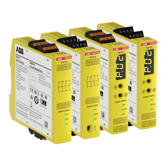
Model overview 11.1 Sentry models The connection blocks are delivered without coding. The coding kit is an optional accessory and is ordered separately. Model Order code Description BSR10 2TLA010040R0000 Screw compression connection blocks. 24VDC Push-in connection blocks. BSR10P 2TLA010040R0001 24VDC BSR11 2TLA010040R0200 Screw compression... -
Page 37: Accessories And Spare Parts
Model Order code Description TSR20 2TLA010061R0000 Screw compression connection blocks. 24VDC Push-in connection blocks. TSR20P 2TLA010061R0001 24VDC TSR20M 2TLA010061R0100 Screw compression connection blocks. 85-265VAC/120-375VDC Push-in connection blocks. TSR20MP 2TLA010061R0101 85-265VAC/120-375VDC USR10 2TLA010070R0000 Screw compression connection blocks. 24VDC Push-in connection blocks. USR10P 2TLA010070R0001 24VDC... -
Page 38: Dimensions
Dimensions All dimensions are in mm. 12.1 Sentry Measure Connection block type Screw connection type Push-in type 22,5 22.5 2TLC010073M0201 Rev.G... -
Page 39: Technical Data
It may represent the result of ABB’s test conditions, and the users must correlate it to actual application requirements. Actual performance is subject to the ABB Warranty and Limitations of Liability. - Page 40 Power supply Internal consumption Required fuse 4 A gG external fuse is required (According to UL248: any (JDYX/7) Fast acting,Ratings 250V, 4A, IR200A) Relay output specification Note 1 Relay output configuration 2 NO + 2 NO Note 1 Maximum operating switching voltage 250 VAC Overvoltage category Rated impulse withstand voltage...
- Page 41 Safety device interface specification Input (I) R1 and R2 Maximum operating input voltage 27.6 VDC Note 1 Minimum input high voltage (VIH 9.8 VDC Note 2 Maximum input low voltage (VIL 6 VDC Typical input impedance 1.5 kΩ Note 3 Maximum current sink (I 20 mA sink...
- Page 42 Electrical operations lifetime Load Σ lth ≤ 13 DC1, DC13 100 000 operations Measurement conditions: • Maximum breaking voltage for relay contacts: 250 V • Maximum switching voltage for relay contacts: 400 V • Rated current • Switching frequency ≤ 0.1 Hz (Switching frequency > 0.1 Hz will shorten life.) •...
- Page 43 EU Directive Compliance Directives European Machinery Directive 2006/42/EC EMC Directive 2014/30/EU RoHS Directive 2011/65/EU RoHS3 Directive 2015/863 UK Regulations Compliance Regulations 2008 No.1597 Supply of Machinery (Safety) Regulations (MD) 2012 No.3032 Restriction of the Use of Certain Hazardous Substances in Electrical and Electronic Equipment Regulations (RoHS) 2016 No.1091 Electromagnetic Compatibility Regulations (EMC)
- Page 44 Standard IEC 61508 3.9E-9 and PFD 7.3E-5 (see chapter 8.2 Scheduled test) EN ISO 13849-1, EN 62061 3.9E-9 Mission time 20 years Information for use in USA/Canada Intended use Applications according to NFPA 79 Power source A suitable isolating source in conjunction with a fuse in accordance with UL248.
-
Page 45: Declaration Of Conformity
Declaration of conformity 2TLC010073M0201 Rev.G... - Page 46 EC Declaration of conformity (according to 2006/42/EC, Annex 2A) ABB Electrification Sweden AB declare that the safety components of ABB AB manufacture SE-721 61 Västerås with type designations and safety functions as listed below, is Sweden in conformity with the Directives...
- Page 47 Declaration of conformity (according to 2008 No 1597) ABB Electrification declare that the safety components of ABB AB manufacture with type Sweden AB designations and safety functions as listed below, is in conformity SE-721 61 Västerås with UK Statutory Instruments (and their amendments) Sweden 2008 No 1597 –...
- Page 48 ABB Electrification Sweden AB SE-721 61 Västerås Sweden...