Table of Contents
Advertisement
User´s manual and
Technical description
ABB Network Partner
( )
I
n =
1A
5A
I
f
( )
n = 50 / 60 Hz
I
n =
0.2A
1A
I
o
SPAJ 141 C
80...265V ~ –
18...80V –
SPCJ 4D24
REGISTERS
0 0 0 0
1
I
/
I
n
L1
2
/
I
I
n
L2
3
I
/
I
n
L3
4
/
I
max
I
(15min)
n
5
(
>
)
[
]
t
I
%
6
(
)
t
> >
[
]
I
%
7
[
]
%
I
I
o
n
8
(
>
)
[
]
t
%
I
o
9
(
> >
)
t
[
]
I
%
o
RS 611
Ser.No.
Combined overcurrent
and earth-fault relay
2
5
U
aux
OPER.IND.
0
1
>
I
START
2
>
I
TRIP
3
> >
I
START
4
> >
I
TRIP
5
>
I
o START
6
>
I
o TRIP
7
> >
I
START
o
8
> >
I
TRIP
o
9
CBFP
SPAJ 141 C
3 >
I
I
I
I
I
I
IRF
o
L1
L2
L3
RESET
I
/
I
>
n
STEP
t [ ]
>
s
k
I
/
I
>>
n
t
[ ]
>>
s
[
]
I
%
I
o >
n
t
[ ]
o >
s
[
]
I
%
I
>>
o
n
t
[ ]
>>
s
o
PROGRAM
SGF
SGB
SGR
TRIP
SPCJ 4D24
Advertisement
Chapters
Table of Contents

Related Manuals for ABB SPAJ 141 C


Summary of Contents for ABB SPAJ 141 C
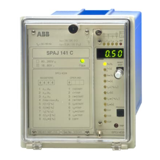
- Page 1 SPAJ 141 C User´s manual and Technical description Combined overcurrent and earth-fault relay 3 > n = 50 / 60 Hz 0.2A SPAJ 141 C 80...265V ~ – RESET > 18...80V – STEP t [ ] > SPCJ 4D24 >>...
-
Page 2: Table Of Contents
Spare parts ........................13 Dimensions and instructions for mounting ..............14 Ordering information ....................15 The complete manual for the relay SPAJ 141 C contains the following partial manuals: General relay description 1MRS 750872-MUM EN General characteristics of D-type relay modules... -
Page 3: Description Of Operation
Remote reset, remote setting control or blocking input for the different current stages Start 2 Blocking or Circuit breaker failure protection 51BF reset Serial I/O Serial communication port Fig. 1. Protective functions of the overcurrent and earth-fault relay SPAJ 141 C. -
Page 4: Connection Diagram
SGR3/7 SGR3/8 SGR1/1 SGR1/3 SGR1/5 SGR1/7 SGR2/1 SGR2/3 SGR2/5 SGR2/7 SGR2/2 SGR2/4 SGR2/6 SGR2/8 SGR1/2 SGR1/4 SGR1/6 SGR1/8 SPA-ZC_ Fig. 2. Connection diagram for the combined overcurrent and earth-fault relay SPAJ 141 C with all the relay matrix switchgroups shown. -
Page 5: Sgr3
T1…T8 Starting and tripping indications SERIAL PORT Serial communication interface SPA-ZC_ Bus connection module Rx/Tx Receiver bus terminal (Rx) and transmitter bus terminal (Tx) of the bus connection module = 63 Fig. 3. Rear view of relay SPAJ 141 C. -
Page 6: Connections
The three phase-currents of the overcurrent pro- the control signals of the output relays B and C Connections tection are connected to terminals 1-2, 4-5 and identical. Normally the output relays B and C 7-8, when the rated current of the secondary are given such a configuration that low-set and circuits is I = 5 A. -
Page 7: Control Signals Between The Modules
SGB / 8 SPCJ 4D24 RELAY RESET Fig. 4. Control signals between the modules of the overcurrent and earth-fault relay SPAJ 141 C. The functions of the blocking and starting sig- of the measuring relay module. The functions nals are selected with the switches of switch- of the different switches are explained in the groups SGF, SGB and SGR. -
Page 8: Operation Indicators
= 50 / 60 Hz 0.2A B) If the display is dark when one of the pro- SPAJ 141 C tective stages I>, I>>, I > or I >> call for a trip- 80...265V ~ –... -
Page 9: Power Supply And Output Relay Module
To be able to operate the relay needs a secured panel. The primary side of the power supply Power supply auxiliary voltage supply. The power supply mod- module is protected with a fuse, F1, located on and output ule forms the voltages required by the measur- the PCB of the module. -
Page 10: Technical Data
Technical data Energizing inputs Rated current I Overcurrent unit Earth-fault unit 0.2 A Thermal withstand capability - continuously 20 A - for 1 s 50 A 100 A 500 A Dynamic current withstand, half-wave value 100 A 250 A 1250 A Input impedance <750 mΩ... - Page 11 Overcurrent unit of SPCJ 4D24 Low-set overcurrent stage I> Setting range 0.5...5.0 x I Selectable modes of operation - definite time operation - operating time t> 0.05...300 s - inverse definite minimum time (IDMT) mode of operation as per IEC 255-4 and BS 142 Extremely inverse Very inverse Normal inverse...
- Page 12 Test voltages *) Dielectric test voltage (IEC 255-5) 2 kV, 50 Hz, 1 min 5 kV, 1.2/50 µs, 0.5 J Impulse test voltage (IEC 255-5) Insulation resistance (IEC 255-5) >100 MΩ, 500 V dc Disturbance tests *) High-frequency (1 MHz) disturbance test (IEC 255-22-1) - common mode 2.5 kV...
-
Page 13: Maintenance And Repairs
When the protective relay is operating under On request, the relay can be given a special treat- Maintenance the conditions specified in the section "Techni- ment for the protection of the printed circuit and repair cal data", the relay is practically maintenance- boards against stress on materials, caused by free. - Page 14 The relay is housed in a normally flush-mounted The relay case is complete with a hinged Dimensions for case. The relay can also be arranged for semi- gasketed, clear, UV-stabilized polycarbonate mounting flush mounting with the use of a 40 mm, 80 mm cover with a sealable fastening screw.
-
Page 15: Ordering Information
- Bus connection module SPA-ZC 21 BB - Fibre-optic cable SPA-ZF AA5, 2 pces - Fibre-optic cable SPA-ZF AA20, 5 pces Ordering numbers for SPAJ 141 C Type designation Name Order number SPAJ 141 C Combined overcurrent and RS 611 007 - AA, -CA, -DA, -FA... - Page 16 Using innovative information technology, Panorama delivers total control of the power process, from generation to consumption. The Panorama standard covers six application areas, each offering specific solutions. ABB Transmit Oy Relays and Network Control P.O.Box 699 FIN-65101 VAASA Finland Tel.
- Page 17 Reset / Step push-button >> Indicators for setting parameters >> o > o > >> >> PROGRAM Programming push-button Indicators for switchgroups SGF, SGB and SGR Trip indicator TRIP Module type designation Fastening screw SPCJ 4D29 ABB Substation Automation Products and Systems...
- Page 18 1MRS 750066-MUM EN General characteristics Issued 95-04-12 of D type relay modules Version A (replaces 34 SPC 3 EN1) Checked JH Approved TK Data subject to change without notice Front panel lay-out ......................1 Contents Control push buttons ..................... 3 Display ...........................
-
Page 19: Control Push Buttons
The front panel of the relay module contains certain position in the main menu to the corre- Control two push buttons. The RESET / STEP push sponding submenu, for entering the setting push-buttons button is used for resetting operation indicators mode of a certain parameter and together with and for stepping forward or backward in the the STEP push button for storing the set values. -
Page 20: Selector Switchgroups Sgf, Sgb, Sgr
Part of the settings and the selections of the Selector switch- operation characteristic of the relay modules in Switch No Pos. Weigth Value groups SGF, SGB various applications are made with the selector and SGR switchgroups SG_ . The switchgroups are soft- ware based and thus not physically to be found in the hardware of the relay module. -
Page 21: Setting Mode
NOTE! During any local man-machine com- any doubt about the settings of the module to be munication over the push buttons and the dis- inserted, the setting values should be read using play on the front panel a five minute time-out a spare relay unit or with the relay trip circuits function is active. - Page 22 MAIN MENU SUBMENUS STEP 0.5 s PROGRAM 1 s Normal status, display off Current on phase L1 Current on phase L2 Current on phase L3 REV. STEP 0.5 s FWD. STEP 1 s Neutral current Io SUBMENUS Second setting Main setting Actual start value I>...
- Page 23 Example 1 Operation in the setting mode. Manual setting for the main setting is 0.80 x I and for the of the main setting of the start current value I> second setting 1.00 x I . The desired main start of an overcurrent relay module.
- Page 24 RESET STEP Set the digit with the STEP push button. 1 1. 0 5 PROGRAM Press the PROGRAM push button to make the 1 1. 0 5 decimal point flash. RESET STEP If needed, move the decimal point with the STEP push button.
- Page 25 Example 2 Operation in the setting mode. Manual setting SGF1/1and SGF1/3 are to be set in position 1. of the main setting of the checksum for the This means that a checksum of 005 should be switchgroup SGF1 of a relay module. The initial the final result.
- Page 26 RESET STEP The switch position is altered to the desired position 1 by pressing the STEP push button once. PROGRAM Using the same procedure the switches SGF 1/ 5 x 1 s 4...8 are called up and, according to the exam- ple, left in position 0.
-
Page 27: Recorded Information
The parameter values measured at the moment Submenu 2 of register A contains a bus commu- Recorded when a fault occurs or at the trip instant are nication monitor for the SPAbus. If the protec- information recorded in the registers. The recorded data, tion relay, which contains the relay module, is except for some parameters, are set to zero by linked to a system including a contol data... -
Page 28: Trip Test Function
Register 0 also provides access to a trip test The selected starting or tripping is activated by Trip test function function, which allows the output signals of the simultaneous pressing of the push buttons relay module to be activated one by one. If the STEP and PROGRAM. - Page 29 Example 3 Trip test function. Forced activation of the outputs. Step forward on the display to register 0. RESET STEP n x 1 s 0 0 0 0 Press the PROGRAM push button for about 3 > five seconds until the three green digits to the right.
- Page 30 To proceed to the next position press the PRO- 3 > GRAM push button for about 1 second until the indicator of the second setting starts flash- 0 0 0 0 ing. RESET > STEP PROGRAM t [ ] > >>...
-
Page 31: Operation Indicators
A relay module is provided with a multiple of indicator is reset by means of the RESET push Operation separate operation stages, each with its own button of the relay module. An unreset opera- indication operation indicator shown on the display and a tion indicator does not affect the function of the common trip indicator on the lower part of the protection relay module. - Page 32 ABB Substation Automation Oy P.O.Box 699 FIN-65101 VAASA Finland Tel. +358 10 22 4000 Fax. +358 10 22 41094...
- Page 33 Main menus and submenus of settings and registers Time/current characteristics Technical data Serial communication Fault codes LAJI - TYP - TYPE NIMITYS-BENÄMNING-NAME Overcurrent and earth-fault relay module SPCJ 4D24 ABB Relays HYVÄKSYNYT TARKASTANUT JAKELU KORVAA-ERSÄTTER-SUPERSEDES LEHTI HAKEMISTO GODKÄND GRANSKAD FÖRDELNING...
- Page 34 D e s c r i p t i o n o f f u n c t i o n Overcurrent unit The overcurrent unit of the combined overcurrent and earth-fault module SPCJ 4D24 is designed for single- phase, two-phase or three-phase operation. It contains two overcurrent stages, i.e. a low-set overcurrent stage I>...
- Page 35 Earth-fault unit The non-directional earth-fault unit of the module SPCJ 4D24 is a single-pole neutral current or residual current overcurrent unit. It contains two neutral overcurrent stages, i.e. a low-set overcurrent stage I > and a high-set overcurrent stage I >>.
- Page 36 B l o c k d i a g r a m SGR3 / 1 SGR1 / 1 50 ms SGR3 / 2 SGR2 / 1 I> t>, k SGR2 / 2 SGR1 / 2 SGR3 / 3 SGF1 / 1 RESET+ SGR1 / 3 SGB / 6...
- Page 37 F r o n t p a n e l Simplified device symbol 3I> Current measurement indicators IL1 IL2 IL3 for phases L1, L2, L3 and I Self-supervision alarm indicator Display I>[In] Indicator for starting value setting of stage I> RESET STEP Indicator for setting ofoperating time t>...
- Page 38 When one of the protection stages of the module performs a tripping, the indicators for the measured values of the module indicate the faulty phase, i.e. in which phase(s) the current has exceeded the setting value of the stage (so called phase fault indication). If for instance, the operation indicator of the I> stage is switched goes on and the indicators IL1 and IL2 are illuminated, the operation was caused by overcurrent in phases L1 and L2.
- Page 39 P r o g r a m m i n g s w i t c h e s Additional functions required by individual applications are selected by means of the switchgroups SGF, SGB and SGR indicated on the front panel. The numbering of the switches, 1...8, and the switch positions 0 and 1 are indicated when setting the switchgroups.
- Page 40 Switch Function SGF2/1 Switches SGF2/1...4 are used for selecting the mode of operation of the starting indicators SGF2/2 of the different stages. When the switches are in position 0 the starting signals are all SGF2/3 automatically reset when the fault is cleared. In order to get a hand reset starting indication SGF2/4 for a stage, the corresponding switch is brought into position 1: SGF2/1 = 1 equals manual resetting of the starting indication of stage I>...
- Page 41 Blocking or control input switchgroup SGB Switch Function SGB/1...4 Switches SGB/1...4 are used when the external control signal BS is to be used for blocking one or more of the current stages of the module. When all the switches are in position 0 no stage is blocked.
- Page 42 Output relay matrix switchgroups SGR1, SGR2 and SGR3 SGR1 The switches of switchgroup SGR1 are used to select the protective stages to be brought to the starting signal output SS1 and the tripping signal output TS2. SGR2 The switches of switchgroup SGR2 are used for configurating the tripping signals of the different protective stages.
- Page 43 Switch Function Factory Checksum number setting value SGR3/1 When SGR3/1 = 1, the starting signal of stage I> is linked to TS1 SGR3/2 When SGR3/2 = 1, the tripping signal of stage I> is linked to TS1 SGR3/3 When SGR3/3 = 1, the starting signal of stage I>> is linked to TS1 SGR3/4 When SGR3/4 = 1, the tripping signal of stage I>>...
- Page 44 M e a s u r e d d a t a The measured values are displayed by the three right-most digits of the display. The currently measured data are indicated by an illuminated LED indicator on the front panel. Indicator Measured data Line current on phase L1 as a multiple of the rated current I...
- Page 45 Neutral overcurrent I measured as a per cent of the rated current of the earth-fault protection. If the earth-fault stage starts or performs a tripping, the current value at the moment of tripping is stored in a memory stack. A new tripping moves the old value up one place in the stack and adds a new value to the stack.
- Page 46 M a i n m e n u s a n d s u b m e n u s s e t t i n g s a n d r e g i s t e r s MAIN MENU SUBMENUS STEP 0.5 s...
- Page 47 The measures required for entering a submenu or a setting mode and how to perform the setting and use the TEST mode are described in detail on Data Sheet 34 SPC 3 EN1 “General characteristics of the D-type SPC plug-in units”. A short form guide to the operations is shown below. Desired step or programming operation Push-button Action...
- Page 48 T i m e / c u r r e n t c h a r a c t e r i s t i c s The operation of the low-set overcurrent stage I> of the module is based on either definite time or inverse time characteristics.
- Page 49 RI-type characteristic The RI-type characteristic is a special characteristic used mainly for time grading with existing mechanical relays. The characteristic is based on the following mathematical expression: t [s] = k / (0.339 - 0.236 x I> / I) where t = operating time in seconds k = time multiplier I = phase current I>...
- Page 50 0.09 0.09 0.08 0.08 0.07 0.07 0.06 0.06 0.05 0.05 0.05 0.04 0.04 0.05 0.03 0.03 0.02 0.02 6 7 8 9 1 0 2 0 I/I> 6 7 8 9 1 0 2 0 I/I> Fig. 3. Inverse-time characteristics of the low-set overcurrent unit in relay module SPCJ 4D24 a) Extremely inverse b) Very inverse PAINOS...
- Page 51 0.05 0.09 0.08 0.07 0.06 0.05 0.04 0.05 0.03 0.02 I/I> 7 8 9 1 0 2 0 I/I> 7 8 9 Fig. 4. Inverse-time characteristics of the low-set overcurrent unit in relay module SPCJ 4D24 a) Normal inverse b) Long-time inverse PAINOS PAINOS...
- Page 52 0.05 0.09 0.08 0.07 0.06 0.05 0.04 0.03 0.02 6 7 8 9 1 0 2 0 I/I> Fig. 5. RI-type inverse-time characteristics of the low-set overcurrent unit in relay module SPCJ 4D24 PAINOS PAINOS...
- Page 53 0.09 0.08 0.07 0.06 0.05 0.04 0.4 0.5 0.05 0.03 0.02 I/I> 7 8 9 10 Fig. 6. RXIDG-type inverse-time characteristics of the low-set overcurrent unit in module SPCJ 4D24 PAINOS PAINOS...
- Page 54 T e c h n i c a l d a t a Low-set overcurrent stage I> Setting range 0.5...5.0 x In Starting time < 70 ms Operating time at definite time mode of operation 0.05...300 s Operating characteristics at IDMT mode of operation Extremely inverse Very inverse...
- Page 55 S e r i a l c o m m u n i c a t i o n p a r a m e t e r s o f t h e S P C J 4 D 2 4 u n i t Event codes When the overcurrent and earth-fault relay module SPCJ 4D24 is linked to the control data communicator SACO 148 D4 over a SPA bus, the module will provide spontaneous event markings e.g.
- Page 56 Event codes of the combined overcurrent and earth-fault relay module SPCJ 4D24: Code/Event Number repre- Default value senting the of the factor event Starting of stage I> Starting of stage I> reset Tripping of stage I> Tripping of stage I> reset Starting of I>>...
- Page 57 Data to be transferred over the serial bus In addition to the spontaneous data transfer the SPA bus allows reading of all input data (I-data) of the module, setting values (S-values), information recorded in the memory (V-data), and some other data. Further, part of the data can be altered by commands given over the SPA bus.
- Page 58 Signal ALARM2 SS3 R, W (P) 0 = signal not active 1 = signal active Signal TRIP TS2 R, W (P) 0 = signal not active 1 = signal active Operate output relays R, W (P) 0= not operated 1 = operated Memorized I>...
- Page 59 PRESENT SETTING VALUES Present starting value for stage I> 0.5...5.0 x In Present operating time for stage I> 0.05...300 s Present starting value for stage I>> 0.5...40 x In 999 = not in use (∞) Present operating time for stage I>> 0.04...300 s Present starting value for stage I >...
- Page 60 SECOND SETTING VALUES Starting value for I> stage, second setting R, W (P) 0.5...5.0 x In Operating time for I> stage, second setting R, W (P) 0.05...300 s Starting value for I>> stage, second setting S43 R, W (P) 0.5...40.0 x In Operating time for I>>...
- Page 61 Number of startings of stage I>> 0...255 Number of startings of stage I > 0...255 Number of startings of stage I >> 0...255 Phase conditions during trip 1 = I >, 2 = I >, 4 = I >, 8 = I >...
- Page 62 Data comm. address of the module V200 R, W 1...254 Data transfer rate V201 R, W 4,8 or 9,6 Bd Programme version symbol V205 042 _ Event register reading time, channel number and event code Re-reading of event register time, channel number and event code Type designation of the module SPCJ 4D24...
- Page 63 F a u l t c o d e s A short time after the internal self-supervision system has detected a permanent relay fault the red IRF indicator is lit and the output relay of the self-supervision system operates. Further, in most fault situations, an auto- diagnostic fault code is shown on the display.