Table of Contents
Advertisement
Quick Links
SPAJ 111 C
Sensitive earth-fault relay
User´s manual and Technical description
= 1A
I
n
80...265V ~ –
18...80V –
SPCJ 1C7
REGISTERS
0 0 0 0
1
2
3
4
5
RS 421
f
n = 50Hz
5A (
I
)
60Hz
SPAJ 111 C
[
]
/
%
I
I
o
n
(
>
)
n
I
o
(
> >
)
n
SGR
I
o
>
[
]
t
t
%
/
> >
[
]
t
t
%
/
0
Ser.No.
B
2
I
o
5
STEP
6.0
I o
>
[ ]
%
U
aux
I
n
1.0
0.5
t
[ ]
>
s
0.05
30
I o
>>
[ ]
%
I
1
n
2
5
3
4
5
6
0.5
7
8
t
[ ]
>>
s
1
0.05
I
IRF
STEP
10
SG1
1
1.0
2
3
4
5
6
7
8
40
0
1
RESET
1.0
I o
I o
>
>>
SPCJ 1C7
Advertisement
Chapters
Table of Contents

Related Manuals for ABB SPAJ 111 C


Summary of Contents for ABB SPAJ 111 C
- Page 1 SPAJ 111 C Sensitive earth-fault relay User´s manual and Technical description = 1A n = 50Hz 5A ( 60Hz SPAJ 111 C STEP 80...265V ~ – > 18...80V – STEP SPCJ 1C7 REGISTERS > 0 0 0 0 0.05 >...
-
Page 2: Table Of Contents
Exchange and spare parts ....................20 Ordering numbers ......................20 Dimensions and mounting ................... 21 Order information ......................21 The complete manual for the sensitive earth-fault relay SPAJ 111 C includes the following submanuals: Sensitive earth-fault relay SPAJ 111 C, general part 1MRS 750809-MUM EN... -
Page 3: Application
CURRENT STAGE OR BOTH SERIAL COMMUNICATION PORT SERIAL I/O BLOCKING *) Definite time only Fig. 1. Protection functions of the sensitive earth-fault relay SPAJ 111 C. The encircled numbers refer to the ANSI (=American National Standards Institute) number of the concerned protection function. -
Page 4: Connections
74 75 ≅ SGR/1 t > Io> t >> Io>> SPAJ 111 C Fig. 2. Connection diagram for the sensitive earth-fault relay SPAJ 111 C. Auxiliary voltage A,B,C,D,E,F Output relays Self-supervision function Blocking signal Start signal Trip signal Switchgroup for configuring trip and alarm signals... - Page 5 Fig. 3. Rear view of sensitive earth-fault relay SPAJ 111 C. Specification of input and output terminals Contacts Function 25-26 Neutral current I = 5 A) 25-27 Neutral current I = 1 A) 10-11 External blocking signal (BS) 61-62 Auxiliary power supply.
- Page 6 The start signal of the I > stage is permanently following functions can be selected with the Configuration of wired to output relay F and the trip signal to switches of the SGR switchgroup on the front output relays output relay A. The trip signal of the I >>...
-
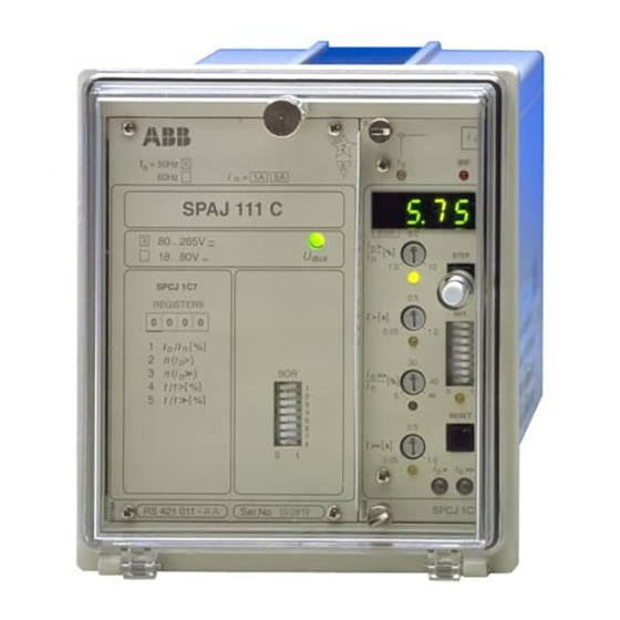
Page 7: Start And Operation Indicators
I is currently = 1A 5A ( n = 50Hz 60Hz being displayed. SPAJ 111 C 3. The red IRF indicator of the self-supervision STEP 80...265V ~ – > system indicates, when lit, that a permanent 18...80V –... -
Page 8: Technical Data
Technical data Energizing inputs Terminals 25-27 25-26 Rated current I Thermal withstand capability Continuous carry 20 A Make and carry for 10 s 25 A 100 A Make and carry for 1 s 100 A 500 A Dynamic current withstand capability, half-wave value 250 A 1250 A... - Page 9 Sensitive earth-fault relay module SPCJ 1C7 Low-set stage I > Start current I >, setting range 0.2...50% I Operate time t> 0.05...10.0 s High-set stage I >> and ∞, infinite Start current I >>, setting range 1...200% I Operate time t>> 0.05...10.0 s Data communication Transmission mode...
-
Page 10: Examples Of Application
1) Blocking signal to be routed to the earth-fault relay of the incoming feeder Fig. 4. Earth-fault relay SPAJ 111 C used for the protection of an outgoing feeder. The earth-fault current is measured with a core-balance current transformer. The selector switch positions are... - Page 11 The two-stage relay also The earth-fault relay SPAJ 111 C is used in enables selective protection arrangements to be applications, where a high accuracy is required.
- Page 12 1) Blocking signal from the earth-fault relay of an outgoing feeder Fig. 5. The sensitive non-directional earth-fault relay SPAJ 111 C used as the earth-fault protection for the infeeder cubicle and the busbars. The selector switch settings are shown in the table on the...
- Page 13 0 not in use 0 no I > trip signal to relay B Σ When the switches are set as above, the output contacts of relay SPAJ 111 C provide the follow- ing signals: Contact Function 65-66 Circuit breaker trip signal, stage I >...
- Page 14 > Io> t >> Io>> SPAJ 111 C Fig. 6. The sensitive non-directional earth-fault relay SPAJ 111 C used as the unbalance protection for a capacitor battery. The selector switch settings are shown in the table on the following page.
- Page 15 0 not in use 0 no I > trip signal to relay B Σ When the switches are set as above, the output contacts of relay SPAJ 111 C provide the follow- ing signals: Contact Function 65-66 Signal on tripping, stage I >...
-
Page 16: Recorded Data And Fault Analysis
The data recorded in the registers of the relay Registers 2 and 3 contain the number of starts of Recorded data can be used both to analyze an earth-fault situ- stage I > and I >> and provide information on and fault analysis ation and to study the behaviour of the protec- the occurrence of earth-faults and on the distri-... - Page 17 1 A or 5 A, of the relay energizing input "Energizing inputs". Fig. 7. Secondary injection test circuit for the earth-fault relay SPAJ 111 C. When the test circuit has been completed and operation of the test circuit can be verified by the selector switches have been properly set, the using a multimeter.
- Page 18 Checking the Apply pure sine-formed test current to the relay by the ammeter. The measurements can, for matching and compare the current value read from the instance, be performed at the rated current of transformers display of the relay with the current value shown the relay.
- Page 19 Checking the high- Set the switches of the SGR switchgroup as The following relay functions are obtained: set stage I >> follows before starting the test: Output rel. Function Switch Position (terminals) A (65-66) (Trip signal of the I > stage) B (68-69) Trip signal of the I >>...
-
Page 20: Exchange And Spare Parts
SPTE 1E12 Bus connection module SPA-ZC 17_ or SPA-ZC 21_ Earth-fault relay Ordering SPAJ 111 C RS 421 011 -AA, CA, DA, FA numbers Earth-fault relay with test adapter RTXP 18 SPAJ 111 C RS 421 211 -AA, CA, DA, FA... -
Page 21: Ordering Numbers
Raising frame SPA-ZX 111 SPA-ZX 112 SPA-ZX 113 Fig. 8. Dimensions of the earth-fault relay SPAJ 111 C. The relay case is made of profile aluminium and vided with a sealable fastening screw. A gasket finished in beige. along the edge of the cover provides an IP54... - Page 23 SPCJ 1C7 Sensitive earth-fault relay module User´s manual and Technical description STEP > STEP > 0.05 >> RESET >> 0.05 > >> SPCJ 1C7...
- Page 24 SPCJ 1C7 1MRS 750810-MUM EN Issued 97-08-05 Sensitive earth-fault Version A (replaces 34 SPCJ 4 EN1) Checked TK relay module Approved TK Data subject to change without notice Features .......................... 2 Contents Function ......................... 3 Block diagram ......................... 4 Front panel ........................5 Start and operation indicators ..................
-
Page 25: Function
The sensitive residual current relay module SPCJ The high-set stage I >> also includes three alter- Function 1C7 is a single pole overcurrent module. It native setting ranges, i.e. 1…8% x I , 5…40% contains two residual overcurrent stages, a low- and 25…200% x I . -
Page 26: Block Diagram
Block diagram Fig. 2. Block diagram for the sensitive residual overcurrent relay module SPCJ 1C7 Energizing current (neutral current or residual current) BS1, BS2, BS3 External blocking signals BTS1 Blocking of the operation of stage I > BTS2 Blocking of the operation of stage I >>... -
Page 27: Front Panel
Front panel Simplified device symbol Self-supervision alarm Current measurement indicator indicator Display for set, measured and recorded values STEP > Indicator and start value STEP setting knob of stage I > Display step push button > Operate time setting knob and indicator of stage I >... -
Page 28: Selector Switches
The setting values are shown by the three which setting value is currently being shown on Settings rightmost digits of the display. An LED indica- the display. tor below each setting knob shows, when lit, >/I Start current of stage I >... -
Page 29: Measured Data
Switch Function SG1/6 Selection of the start current setting range of the high-set stage I >>. SG1/7 SG1/6 SG1/7 Setting range I >> 5…40% x I 1…8% x I 25…200% x I 5…40% x I SG1/8 Selection of the setting range of the operate time t>> of stage I >>... -
Page 30: Recorded Information
The leftmost digit of the display shows the digits the value of the register. Recorded address code of the register and the other three information Register/ Recorded information STEP Maximum current measured as a multiple of the rated current of the protection. The value of the register is updated, if one of the following conditions are fulfilled. -
Page 31: Menu Chart
Menu chart MAIN MENU SUBMENUS STEP 0,5 s RESET 1 s Normal state, display dark = in setting mode adjustable value STEP BACKWARD 0,5 s STEP FORWARD 1 s Measured residual current Io SUBMENUS Remotely set Remotely set Start current of stage Io> percentage p1 value Io>... -
Page 32: Technical Data
Technical data Low-set stage I > Start current 0.2…2% x I 1…10% x I 5…50% x I Start time, typically 75 ms Operate time t>, definite time 0.05...1.00 s or 0.5...10.0 s Reset time, typically 70 ms Reset ratio, typically 0.96 ±2% of set value or ±40 ms Operate time accuracy... -
Page 33: Event Codes
Over the SPA bus the substation communica- event mask is formed by multiplying the weight Event codes tion system can read event data of the relay factors by 0 (event not included in the report- module SPCJ 1C7, e.g. start and trip events. ing) or 1 (event included in the reporting) and Event information read are printed out in the adding the weight factors so received, compare... -
Page 34: Remote Transfer Data
Apart from the event codes the substation com- given over the SPA bus. All the data are availabe Remote transfer munication system can read, via the SPA bus, all on channel 0 data input data (I data), output data (O data), setting values (S data), information recorded in the R = data can be read from the module memory (V data), and some other data. - Page 35 Data Code Data Value direction Max. measured current or current 0…250% x I measured at relay operation Number of starts of stage I > 0…255 Number of starts of stage I >> 0…255 Duration of the latest start situation 0…100% of stage I >...
- Page 36 Data Code Data Value direction Relay module type designation SPCJ 1C7 reading of event register Time, channel number and event code Re-reading of event register Time, channel number and event code Reading of relay module state data 0 = normal state 1 = module been subject to automatic reset 2 = overflow of event...
- Page 37 Shortly after the self-supervision system has fault code consists of a red number 1 (one), and Fault codes detected a permanent internal fault in the relay a green, one to three digit code number. When module the red IRF (Internal Relay Fault) indi- a fault is detected the fault code should be cator is lit.
- Page 39 General characteristics of C-type relay modules User´s manual and Technical description > >> Self-supervision alarm indicator Indicators for measured values (Internal Relay Fault) Display, 1 + 3 digits STEP > Setting knob 1 STEP with indicator Step push-button (STEP) Stage 1 >...
- Page 40 1MRS 750328-MUM EN General characteristics of Issued 96-02-19 C-type relay modules Version A (replaces 34 SPC 2 EN1) Checked L-W U Approved TK Data subject to change without notice Push-buttons ........................2 Contents Programming switches SG1 .................... 2 Setting knobs ........................3 Display ...........................
-
Page 41: Setting Knobs
Most of the operating values and operating In addition to the settings made with the setting Setting knobs times are set by means of the setting knobs on knobs, most modules allow so called remote the front panel of the relay module. Each setting setting. -
Page 42: Display Submenu
Display submenu Less important values and values not very often display moves forward when pressing the STEP set are displayed in the submenus. The number button for one second and backward when of submenus varies with different relay module pressing it for 0.5 seconds. The return to the types. - Page 43 Example 1: Function in the setting mode. Manual setting of the address code of a relay module and the data Set the digit by means of the STEP button. transfer rate for the serial communication. The initial value for the address code is 146. Press push-button STEP until register address A appears on the display.
-
Page 44: Stored Information
Stored information The parameter values measured at the moment Register A contains the address code of the relay when a fault occurs are recorded in the registers, module as required by the serial communication in some modules also the setting values. The system. -
Page 45: Trip-Test Mode
Trip-test mode Register 0 also allows access to the so called The selected starting or tripping is activated by Trip-test function, which allows the output simultaneous pressing of the push-buttons STEP signals of the relay module to be activated one by and RESET. - Page 46 Example 2: Trip-test function. Forced activation of the out- puts is made as follows: Press the RESET button for about 1 second until the indicator of the second setting knob starts flashing. Step forward on the display to register 0. Press the push-buttons RESET and STEP si- multaneously to activate tripping of stage 1 (e.g.
- Page 47 A measuring relay module is provided with two The operation indicator starts glowing yellow Operation separate operating stages, each of which with its when the operating stage starts and red when a indicators own yellow/red operation indicator on the lower delayed tripping operates.
- Page 48 ABB Substation Automation Oy P.O.Box 699 FIN-65101 VAASA Finland Tel. +358 (0)10 22 4000 Fax.+358 (0)10 22 41094 www.abb.com/substationautomation...