Table of Contents
Advertisement
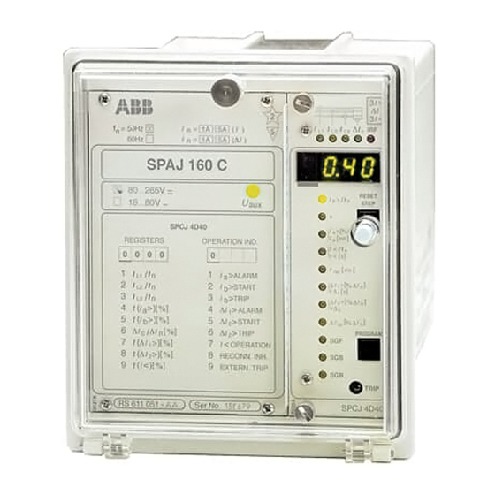
SPAJ 160 C
Capacitor protection relay
User´s manual and Technical description
= 1A
I
n
I
=
n
REGISTERS
0 0 0 0
1
2
3
4
5
6
7
8
9
RS 421
f
n = 50Hz
5A (
I
)
∆
I
60Hz
1A
5A
(
)
SPAJ 160 C
80...265V ~ –
18...80V –
SPCJ 4D40
OPERATION IND.
0
1
I
/
I
I a
n
L1
2
I
/
I
I b
n
L2
3
/
I
I
I b
n
L3
∆
(
>
)
[
]
4
t
%
I a
I
∆
(
)
5
t
>
[
%
]
I b
I
∆
∆
∆
6
[
]
%
I
/
I
I
c
n
∆
(
)
[
]
7
<
t
>
%
I
I
1
∆
(
)
8
t
>
[
]
I
%
RECONN. INH.
2
9
(
< %
)
[
]
t
I
EXTERN. TRIP
Ser.No.
2
I
I
L1
5
I
U
aux
k
I
t
I
t
t
>
ALARM
∆
>
START
t
>
TRIP
∆
k
>
ALARM
1
∆
>
START
2
>
TRIP
2
SGF
OPERATION
SGB
SGR
3
I >
∆
I
3
I <
∆
I
I
IRF
c
L2
L3
RESET
/
I
>
b
n
STEP
[
]
>
%
I
a
b
[
]
a min
< I
/
n
[ ]
< s
[
]
rec min
∆
[
]
>
I
%
I
n
1
∆
[ ]
s
1
∆
[
]
>
%
I
I
n
2
∆
2
∆
[
]
%
I
I
n
cs
PROGRAM
TRIP
SPCJ 4D40
Advertisement
Chapters
Table of Contents

Related Manuals for ABB SPAJ 160 C


Summary of Contents for ABB SPAJ 160 C
- Page 1 SPAJ 160 C Capacitor protection relay User´s manual and Technical description I > ∆ I < ∆ = 1A n = 50Hz 5A ( ∆ 60Hz SPAJ 160 C 80...265V ~ – RESET > STEP 18...80V – SPCJ 4D40 >...
-
Page 2: Table Of Contents
SPAJ 160 C 1MRS 750064-MUM EN Issued 95-05-02 Capacitor protection relay Modified 97-10-16 Version D Checked GL Approved YK Data subject to change without notice Characteristics ........................ 2 Contents Area of application (modified 97-10) ................3 Description of operation (modified 96-11) ..............5 Connection diagram ....................... -
Page 3: Area Of Application (Modified 97-10)
The main application area for the relay is to be included. All these functions can be found Area of protect capacitor banks intended for reactive in SPAJ 160 C. application power compensation and filtering of the har- (modified 97-10) monics. - Page 4 SPAJ 140 C or SPAJ 141 C 3I/U> SPAJ 160 C I/U< Fig.3. Protection of a capacitor bank connected as a double-star in an industrial network with two- or three-phase current measurement. In this case a non-directional earth-fault protection is used.
-
Page 5: Description Of Operation (Modified 96-11)
The protective relay measures the phase currents The alarm stage has a definite time characteris- Description of of the capacitor bank one-, two- or three phase. tic. Both the starting value and the operating operation The currents are internally transformed by the time are available for setting. - Page 6 WITH ALARM/TRIP STAGE RECONNECTION ENABLE UNDERCURRENT DETECTION FOR RECONNECTION INHIBIT ∆ ∆ ∆ ∆ RECONNECTION INHIBIT TIMER CONTROL INPUT BS1 SERIAL I/O SERIAL COMMUNICATION Fig. 7. Checking functions of the capacitor bank overload and unbalance prot. relay type SPAJ 160 C.
-
Page 7: Connection Diagram
RELAY RESET SPAJ 160 C SPCJ 4D40 Fig. 8. Complete connection diagram for the capacitor bank protection relay SPAJ 160 C with all the relay matrix and blocking/control input programming switches shown. Auxiliary voltage A, B, C, D, E, F... - Page 8 Made in Finland Fig. 9. Rear view of relay SPAJ 160 C...
-
Page 9: Connections
Connections Terminal Function Phase current I , 5 A Phase current I , 1 A Phase current I , 5 A Phase current I , 1 A Phase current I , 5 A Phase current I , 1 A 25-26 Phase unbalance current 5 A 25-27 Phase unbalance current 1 A... - Page 10 Fig. 10. Control signals between the modules of the capacitor bank relay SPAJ 160 C. The functions of the blocking, starting and trip- the setting menu of the measuring relay mod- ping signals are selected with the switches of ule.
-
Page 11: Abbreviations Of Signal Names
Starting Signal 1 Starting Signal 2 Starting Signal 3 Tripping Signal 1 Tripping Signal 2 AR1...3 Auto-Reclose starting signals (not used in SPAJ 160 C) Internal Relay Fault signal Starting Signal 1 Switch Groups for functions SGB1...3 Switch Groups for blockings SGR1...2... -
Page 12: Operation Indicators
= 50Hz = 1A 5A ( ∆ 60Hz C) Besides being a code number at data presen- SPAJ 160 C tation, the leftmost red digit in the display serves 80...265V ~ – RESET as a visual operation indicator. An operation >... - Page 13 D) The operation indicator on the display and ton. The persistent indications are obtained the "TRIP" indicator persist when the protec- through the following programming: tive stage returns to normal. The indicators are Switch SGF/3 = 1 Starting indication on I >...
-
Page 14: Power Supply And Output Relau Module
To be able to operate the relay needs a secured panel. The primary side of the power supply Power supply auxiliary voltage supply. The power supply mod- module is protected with a fuse, F1, located on and output ule forms the voltages required by the measur- the PCB of the module. -
Page 15: Technical Data (Modified 96-11)
Technical data Energizing inputs (modified 96-11) Phase and neutral current inputs, terminals 1-3, 4-6, 7-9, 25-27 1-2, 4-5, 7-8, 25-26 Rated current I Thermal withstand capability - continuously 20 A - for 1 s 100 A 500 A Dynamic current withstand, half-wave value 250 A 750 A Input impedance... -
Page 16: Tripping Signal
Protection units of module SPCJ 4D40 Overload stage I > Starting current I > 0.30...1.50 x I Starting time <80 ms Operation characteristic ANSI inverse Time multiplier k 0.2...2.0 Resetting time <100 ms Drop-off/pick-up ratio >0.95 Operation time accuracy ±10% of theoretical value or ±50 ms (k = 1.0 and I >... - Page 17 Data transmission Transmission mode Fibre optic serial bus Data code ASCII Data transfer rate, selectable 4800 Bd or 9600 Bd Electrical/optical bus connection module powered from the host relay - for plastic core cables SPA-ZC 21 BB - for glass fibre cables SPA-ZC 21 MM Electrical/optical bus connection module powered from the host relay or an external...
-
Page 18: Maintenance And Repairs
SPA-ZC 17_ or SPA-ZC 21_ Capacitor bank protection without testswitch Ordering numbers SPAJ 160 C RS 611 051 - AA, CA, DA, FA Capacitor bank protection with testswitch type RTXP 18 SPAJ 160 C RS 611 251 - AA, CA, DA, FA... -
Page 19: Ordering Numbers
Raising frame SPA-ZX 111 SPA-ZX 112 SPA-ZX 113 Example Information 1. Quantity and type designation 15 pcs SPAJ 160 C required with 2. Ordering number RS 611 051 - AA order 3. Rated frequency = 50 Hz 4. Auxiliary voltage = 110 V dc 5. - Page 21 General characteristics of D-type relay modules User´s manual and Technical description 3 > Relay symbol Fastening screw Self-supervision alarm indicator Indicators for measured (Internal Relay Fault) quantities Display, 1 + 3 digits RESET > STEP t [ ] > Reset / Step push-button >>...
- Page 22 1MRS 750066-MUM EN General characteristics Issued 95-04-12 of D type relay modules Version A (replaces 34 SPC 3 EN1) Checked JH Approved TK Data subject to change without notice Front panel lay-out ......................1 Contents Control push buttons ..................... 3 Display ...........................
-
Page 23: Display
The front panel of the relay module contains certain position in the main menu to the corre- Control two push buttons. The RESET / STEP push sponding submenu, for entering the setting push-buttons button is used for resetting operation indicators mode of a certain parameter and together with and for stepping forward or backward in the the STEP push button for storing the set values. -
Page 24: Settings
Part of the settings and the selections of the Selector switch- operation characteristic of the relay modules in Switch No Pos. Weigth Value groups SGF, SGB various applications are made with the selector and SGR switchgroups SG_ . The switchgroups are soft- ware based and thus not physically to be found in the hardware of the relay module. -
Page 25: Setting Mode
NOTE! During any local man-machine com- any doubt about the settings of the module to be munication over the push buttons and the dis- inserted, the setting values should be read using play on the front panel a five minute time-out a spare relay unit or with the relay trip circuits function is active. - Page 26 MAIN MENU SUBMENUS STEP 0.5 s PROGRAM 1 s Normal status, display off Current on phase L1 Current on phase L2 Current on phase L3 REV. STEP 0.5 s FWD. STEP 1 s Neutral current Io SUBMENUS Second setting Main setting Actual start value I>...
- Page 27 Example 1 Operation in the setting mode. Manual setting for the main setting is 0.80 x I and for the of the main setting of the start current value I> second setting 1.00 x I . The desired main start of an overcurrent relay module.
- Page 28 RESET STEP Set the digit with the STEP push button. 1 1. 0 5 PROGRAM Press the PROGRAM push button to make the decimal point flash. 1 1. 0 5 RESET STEP If needed, move the decimal point with the STEP push button.
- Page 29 Example 2 Operation in the setting mode. Manual setting SGF1/1and SGF1/3 are to be set in position 1. of the main setting of the checksum for the This means that a checksum of 005 should be switchgroup SGF1 of a relay module. The initial the final result.
- Page 30 RESET STEP The switch position is altered to the desired position 1 by pressing the STEP push button once. PROGRAM Using the same procedure the switches SGF 1/ 5 x 1 s 4...8 are called up and, according to the exam- ple, left in position 0.
- Page 31 The parameter values measured at the moment Submenu 2 of register A contains a bus commu- Recorded when a fault occurs or at the trip instant are nication monitor for the SPAbus. If the protec- information recorded in the registers. The recorded data, tion relay, which contains the relay module, is except for some parameters, are set to zero by linked to a system including a contol data...
-
Page 32: Trip Test Function
Register 0 also provides access to a trip test The selected starting or tripping is activated by Trip test function function, which allows the output signals of the simultaneous pressing of the push buttons relay module to be activated one by one. If the STEP and PROGRAM. - Page 33 Example 3 Trip test function. Forced activation of the outputs. Step forward on the display to register 0. RESET STEP n x 1 s 0 0 0 0 Press the PROGRAM push button for about 3 > five seconds until the three green digits to the right.
- Page 34 To proceed to the next position press the PRO- 3 > GRAM push button for about 1 second until the indicator of the second setting starts flash- 0 0 0 0 ing. RESET > STEP PROGRAM t [ ] > >>...
-
Page 35: Operation Indicators
A relay module is provided with a multiple of indicator is reset by means of the RESET push Operation separate operation stages, each with its own button of the relay module. An unreset opera- indication operation indicator shown on the display and a tion indicator does not affect the function of the common trip indicator on the lower part of the protection relay module. - Page 37 SPCJ 4D40 Capacitor relay module User´s manual and Technical description I > ∆ I < ∆ RESET > STEP > a min < I < s rec min ∆ ∆ > ∆ ∆ ∆ > ∆ ∆ ∆ PROGRAM TRIP SPCJ 4D40...
- Page 38 SPCJ 4D40 1MRS 750065-MUM EN Issued 96-04-12 Capacitor bank Modified 99-10-18 Version D protection relay module Checked GL Approved YK Data subject to change without notice Contents Characteristics ........................ 2 Description of function (modified 97-10) ............... 3 Block diagram ......................... 5 Front panel ........................
-
Page 39: Description Of Function (Modified 97-10)
The purpose of the overload unit is to protect The operation of both overload stages can be Description of the capacitor bank against overload and har- blocked by bringing a blocking signal BS1, BS2 function monic currents. The faults that may occur are or RRES to the unit. - Page 40 Undercurrent unit The undercurrent unit is intended to be used to an acceptable level. The operation indicator for the detection of capacitor disconnection. 8 is lit when t is running. With loss of voltage in the feeding bus the ca- pacitor has to be disconnected from the system The stage starts if all the three phase currents to prevent reapplication of the voltage of the...
-
Page 41: Block Diagram
20.0% ∆I Compensation for Usually there are some natural unbalance in a is used. The capacitor bank natural natural unbalance three phase reactive compensation capacitor unbalance current is compensated for both bank. An unbalance compensation facility has amplitude and phase angle. Phase current in- therefore been implemented in the protective put I is used as synchronizing input for the... -
Page 42: Front Panel
Front panel I > ∆ Simplified device symbol I < ∆ Indicators for measured Self-supervision alarm current values, indicator phases L1, L2, L3 and ∆I Display Indicator for setting I > RESET > STEP Reset and display step Indicator for setting k push-button Indicator for setting I >... -
Page 43: Operation Indicators
Each stage has its own operation indicator If start of a stage does not last long enough to Operation shown as a red figure to the left in the digital cause a trip, the start indication on the display indicators display. -
Page 44: Settings
The setting values are shown by the right-most to a setting value symbol shows which setting Settings three digits of the display. A lit indicator close value is indicated on the display. Setting Parameter Setting range Factory setting > The starting value of the overload stage I >... - Page 45 The reconnection inhibit output can be disabled by means of this switch Note! This switch is only to be used if the module SPCJ 4D40 is used elsewere than in SPAJ 160 C. When SGF/5=0, the reconnection inhibit relay is in use When SGF/5=1, the reconnection inhibit relay is disabled Increase the inverse time characteristic for phase unbalance stage ∆I...
- Page 46 Blocking or control Switch Function Factory input switchgroups setting SGB1, SGB2 and SGB3 SGB1/1 Switches SGB1/1...3 are used when the external control signal BS1 is to SGB1/2 be used for blocking one or more of the current stages of the module. SGB1/3 When all the switches are in position 0 no stage is blocked When SGB1/1=1, the tripping of overload stages I >...
- Page 47 Switch Function Factory setting SGB2/1 Switches SGB2/1...3 are used when the external control signal BS2 is to SGB2/2 be used for blocking one or more of the current stages of the module. SGB2/3 When all the switches are in position 0 no stage is blocked When SGB2/1=1, the tripping of overload stages I >...
- Page 48 Switch Function Factory setting SGB3/1 Switches SGB3/1...3 are used when the external control signal RRES is SGB3/2 to be used for blocking one or more of the current stages of the module. SGB3/3 When all the switches are in position 0 no stage is blocked When SGB3/1=1, the tripping of overload stages I >...
- Page 49 Output relay matrix Switch Function Factory switchgroups SGR1 setting and SGR2 SGR1/1 When SGR1/1=1, the overload stage I > alarm output is linked to SS1 SGR1/2 When SGR1/2=1, the overload stage I > start signal is linked to SS1 SGR1/3 When SGR1/3=1, the unbalance stage ∆I >...
-
Page 50: Recorded Data
When the relay performs a tripping, the cur- trip occurs, the oldest set of values will be lost. Recorded data rent values at the moment of tripping, the du- A master reset of the relay erases all the con- ration of the starting for different units and other tents of both of the register blocks. - Page 51 Register Recorded information Display of blocking signals and other external control signals. The right-most digit indicates the state of the blocking inputs of the unit. The following states may be indicated: 0 = no blocking signal 1 = the control or block signal BS1 is active 2 = the control or block signal BS2 is active 3 = the control or block signals BS1 and BS2 are active 4 = the control or block signal RRES is active...
-
Page 52: Main Menus And Submenus Of Settings And Registers
Main menus and submenus of settings and Normal status, display off MAIN MENU SUBMENUS registers STEP 0.5 s PROGRAM 1 s Current on phase L1 Current on phase L2 Current on phase L3 Compensated unbalance Measured unbalance current ∆Ic current ∆I Starting value setting I >... - Page 53 The measures required for entering a submenu detail on data sheet "General characteristics of or a setting mode and how to perform the set- the D-type plug-in units". Below a short guide. ting and use the TEST mode are described in Desired step or operation Push-button Action...
- Page 54 The operation of the overload stage I > is based Time/current on ANSI and IEC inverse time characteristic. characteristics ANSI-type I/Ib> t [s] standard durations [s] characteristic 1.15 1620 1800 IEC 871-1 1.20 IEC 871-1 1.30 ANSI 18-1980, IEC 871-1 1.40 13.5 ANSI 18-1980...
- Page 55 100000 10000 1000 0.01 I/Ib> 1.00 1.10 1.20 1.30 1.40 1.50 1.60 1.70 1.80 1.90 2.00 2.10 2.20 Fig 5. ANSI-time characteristics of the capacitor bank protection module SPCJ 4D40 Durations specified in the ANSI and IEC standards are marked with "o" in the figure.
- Page 56 ∆ 0.01 ∆ ∆ 1.00 1.10 1.20 1.30 1.40 1.50 1.60 1.70 1.80 1.90 2.00 Ic/ I2> Fig 6. Phase unbalance inverse-time characteristics of the capacitor bank protection module SPCJ 4D40. When the switch SGF/6 is in position 0 the operating times are according fig 6. In position 1 the operating times are increased by a factor 10.
- Page 57 Technical data Overload stage I > Starting current I > 0.30...1.50 x I Starting time <80 ms Operation characteristic ANSI inverse Time multiplier k 0.2...2.0 Resetting time <100 ms Drop-off/pick-up ratio >0.95 Operation time accuracy ±10% of theoretical value or ±50 ms, see Fig. 5 (k = 1.0 and I >...
-
Page 58: Event Codes
When the capacitor bank protection module An event buffer is capable to memorize up to Event codes SPCJ 4D40 is linked to a control data commu- eight events. If more than eight events occure nicator over the SPA bus, the module will pro- before the content of the buffer is send to the vide time stamped event markings e.g. -
Page 59: Data To Be Transferred Over The Bus
Code Event Number Default value representing of the factor the event Output signal TS1 activated Output signal TS1 reset Output signal SS1 activated Output signal SS1 reset Output signal SS2 activated Output signal SS2 reset Output signal SS3 activated Output signal SS3 reset Output signal TS2 activated Output signal TS2 reset Default checksum for mask V158... - Page 60 Data Code Data flow Value range direction OUTPUTS Starting of stage I > 0 = I >-stage not started 1 = I >-stage started Tripping of stage I > 0 = I >-stage not tripped 1 = I >-stage tripped Starting of stage I >...
- Page 61 Data Code Data flow Value range direction Memorized starting of stage ∆I 0 = ∆I > >-stage not started 1 = ∆I >-stage started Memorized tripping of stage ∆I 0 = ∆I > >-stage not tripped 1 = ∆I >-stage tripped Memorized external trip signal 0 = signal not active 1 = signal active...
- Page 62 Data Code Data flow Value range direction Number of startings of stage I > 0...255 Number of startings of stage I > 0...255 Number of startings of stage ∆I > 0...255 Number of startings of stage ∆I > 0...255 Number of startings of stage I< 0...255 Phase condition during trip 1 = I...
- Page 63 The event register can be read by the L-com- The setting values S1...S18 are the setting val- mand only once. If a fault occurs e.g. in the ues used by the protection stages. All the set- data transfer, the contents of the event register tings can be read or written.
- Page 64 ABB Oy Substation Automation P.O.Box 699 FIN-65101 VAASA Finland Tel. +358 (0)10 22 11 Fax.+358 (0)10 22 41094 www.abb.com/substationautomation...