Table of Contents
Advertisement
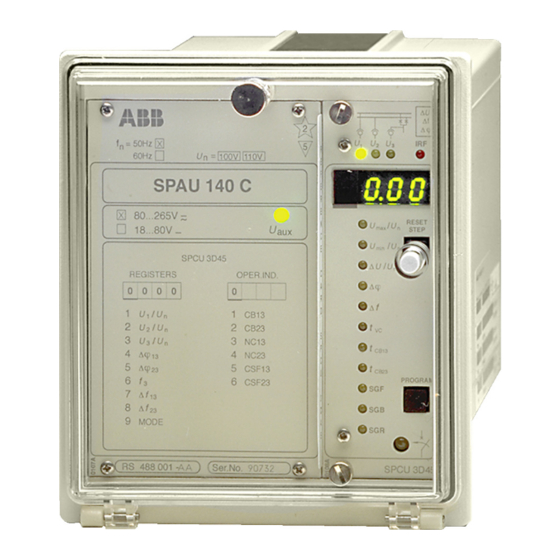
SPAU 140 C
Synchro-check relay
User´s manual and Technical description
f
n = 50Hz
60Hz
80...265V ~ –
18...80V –
REGISTERS
0 0 0 0
1
2
3
4
5
6
7
8
9
RS 488
= 100V 110V
U
n
SPAU 140 C
SPCU 3D45
OPER.IND.
0
1
U
/
U
CB13
1
n
2
/
U
U
CB23
2
n
3
U
/
U
NC13
3
n
ϕ
∆
4
NC23
13
ϕ
∆
5
CSF13
23
6
f
CSF23
3
∆
f
13
∆
f
23
MODE
Ser.No.
2
U
U
U
2
5
1
U
U
max
aux
U
min
∆
U
/
ϕ
∆
∆
f
t
VC
t
CB13
t
CB23
SGF
SGB
SGR
SPCU 3D45
∆
U
∆
f
ϕ
∆
I
IRF
o
3
RESET
/
U
n
STEP
/
U
n
U
n
PROGRAM
Advertisement
Chapters
Table of Contents

Related Manuals for ABB SPAU 140 C


Summary of Contents for ABB SPAU 140 C
- Page 1 SPAU 140 C Synchro-check relay User´s manual and Technical description ∆ ∆ ϕ ∆ n = 50Hz = 100V 110V 60Hz SPAU 140 C 80...265V ~ – RESET STEP 18...80V – SPCU 3D45 ∆ REGISTERS OPER.IND. ϕ ∆ 0 0 0 0 ∆...
-
Page 2: Table Of Contents
SPAU 140 C 1MRS 750315-MUM EN Issued 96-02-19 Synchro-check relay Version A Checked TK Approved TK Data subject to change without notice Features .......................... 3 Contents Application ........................3 Description of operation ....................4 Connection diagram ....................... 6 Connections ........................8 Application example 1 .................... -
Page 3: Application
Serial port for connecting the relay to the elec- trical or optical SPA bus The synchro-check relay SPAU 140 C is an in- can be used for closing ring mains, intercon- Application tegrated microprocessor-based voltage measur-... - Page 4 The relay incorporates two identical stages tacts of the circuit breaker close. This duration Description of which operate as independent units. Both stages is determined on the basis of the frequency and operation of the synchro-check relay has two parallel func- phase difference measured.
- Page 5 CS13 Closing command Serial communication I/O signal CS23 Serial communication Fig. 1. Supervision functions of synchro-check relay SPAU 140 C. The encircled numbers refer to the ANSI number of the concerned function. (ANSI = American National Standards Institute)
-
Page 6: Connection Diagram
CS23 CSF23 SGR/7 SGB/4 SPAU 140 C Fig. 2. Complete connection diagram for the synchro-check relay SPAU 140 C. The switches for configuring the control signals of the output relays and the external blocking/control inputs are illustrated in the diagram. - Page 7 Made in Finland = 63 Fig. 3. Rear view of synchro-check relay SPAU 140 C Auxiliary voltage A,B,C,D Output relays Self-supervision Switchgroup for the configuration of blocking and command signals Switchgroup for the configuration of alarm signals CB13 Circuit breaker close permission/close command, stage 1...
-
Page 8: Connections
Connections Terminal Function 13-14 Measured voltage U1, rated voltage 100 V 13-15 Measured voltage U1, rated voltage 110 V 16-17 Measured voltage U2, rated voltage 100 V 16-18 Measured voltage U2, rated voltage 110 V 19-20 Measured voltage U3, rated voltage 100 V 19-21 Measured voltage U3, rated voltage 110 V The relay is able to measure either phase-to-phase voltages or phase-to-neutral... -
Page 9: Application Example 1
SPAU 140 C performs a erator are in synchronism, closes the circuit voltage check, as the line AB is deenergized breaker. SPAU 140 C SPAU 140 C Auto-reclosure relay Fig. 4. Synchro-check relay SPAU 140 C checking energizing conditions and synchronism. -
Page 10: Application Example 2
SGR/7 SGB/4 SPAU 140 C Fig. 5. Synchro-check relay SPAU 140 C used for checking synchronism between busbar and line In the application illustrated in Fig. 5 stage 1 of cuit breaker is not closed within the preset time, the synchro-check relay is used for checking the an alarm signal will be received through con- synchronism between the busbar and the line. - Page 11 ALARM SGF/5 VC23 SGF/8 SGF/6 SPCU 3D45 SPTU __ R4 Fig. 6. Control signals between the modules of the synchro-check relay SPAU 140 C and the configuration switches. U1,U2,U3 Measured voltages CB13 Close permission/close command, stage 1 CB23 Close permission/close command, stage 2...
-
Page 12: Operation Indicators
60Hz = 100V 110V stages of the synchro-check relay. Operation is SPAU 140 C indicated by a red digit, 1 or 2, depending on 80...265V ~ – which of the stages that activated its close sig- RESET 18...80V –... -
Page 13: Power Supply And Output Relay Module
The combined power supply and I/O relay A green LED indicator U on the system panel Power supply module is located behind the relay's system is lit when the power supply module is in op- and output relay panel. The module incorporates the power sup- eration. - Page 14 Synchro-check relay module SPCU 3D45 Synchro-check function Upper voltage level threshold U Setting range 0.5...1.0 x U Voltage difference ∆U Setting range 0.02...0.4 x U Frequency difference ∆f Setting range 0.02...0.5 Hz Phase difference ∆ϕ 5...50° Operate time when the voltage on the 160 ms ±...
- Page 15 Mode of operation Command mode or continuous mode operation Command mode operation Max. close signal length t PULSE command mode operation Setting range 0.2...20 s Time permitted for checking and request for CB closing t CHECK Setting range 0.05...300 s Data transmission Transmission mode Fibre-optic serial bus...
- Page 16 The relay incorporates a self-supervision logic the synchro-check relay, from the instrument Commissioning that continuously supervises the operation of transformers to the circuit breakers. and testing the relay and provides an IRF alarm when an internal relay fault is detected. However, the Special attention should be paid to the connec- manufacturer recommends regular testing of the tion of the relay.
- Page 17 Miniature circuit- Supervision of the condition of the relay's ex- - Configure switchgroup SGF so that the check- breakers of the ternal measuring circuit is not incorporated in sum is 136. Then the stages operate when the voltage measuring the synchro-check relay. Should the external operate time t expires.
-
Page 18: Maintenance And Repairs
= 60 Hz and U = 18...80 V dc Type Example Order data 1. Quantity 15 relays SPAU 140 C 2. Order number RS 488 001 - AA 3. Rated frequency = 50 Hz 4. Auxiliary voltage = 110 V dc 5. - Page 19 SPA-ZX 111 SPA-ZX 112 SPA-ZX 113 Fig. 7. Dimension and mounting drawings for synchro-check relay SPAU 140 C. The relay case is made of anodized profile alu- degree of protection between the case and the minium and finished in beige.
- Page 21 SPCU 3D45 Synchro-check relay module User´s manual and Technical description ∆ ∆ ϕ ∆ RESET STEP ∆ ϕ ∆ ∆ CB13 CB23 PROGRAM SPCU 3D45...
- Page 22 SPCU 3D45 1MRS 750195-MUM EN Issued 96-02-13 Synchro-check Version A (replaces 34 SPCU 11 EN1) Checked TK relay module Approved TK Data subject to change without notice Features .......................... 2 Contents Description of operation ....................3 Synchro-check function ..................... 4 Voltage-check function ....................
-
Page 23: Description Of Operation
The synchro-check module SPCU 3D45 in- between bus voltage U1 and line voltage U3 and Description of cludes two identical operation stages and both operation stage 2 similarly checks the closing operation stages are provided with a synchro-check and a conditions between bus voltage U2 and line voltage-check function. - Page 24 Synchro-check The synchro-check function is used for check- - The network sections to be connected (vol- function ing whether CB closing is permitted or not. tages) have the same phase angle. The phase Before CB operation the following closing con- angle conditions are fulfilled when the allowed ditions must be fulfilled: phase angle difference between the network...
-
Page 25: Voltage-Check Function
Voltage-check The voltage-check function is required when a direction of the module can be selected by means function disconnected bus/line is to be connected to an of function selector switches and the settings energized section of a network. By means of the determine which side of the circuit breaker to threshold voltages U and U... -
Page 26: Operation Mode Indicators
When a closing command for the circuit breaker set. At the same time the digital display on the Operation mode is permitted, the synchro-check relay module front panel indicates with a red digit 1 or 2 indicators activates the closing signals of one or both of which stage has delivered the closing signal. - Page 27 Continuous mode In the continuous mode operation the closing module. Beside the closing conditions in force, operation signal output of the synchro-check relay is ac- the only thing affecting the continuous mode tive as long as the closing conditions are ful- operation is an external blocking signal applied filled and disappears when the conditions cease.
- Page 28 Command mode In command mode operation an external com- of a closing signal pulse to the circuit breaker. operation mand signal, besides the normal closing condi- If, after the delivered command signal for clos- tions, is needed for delivering of the closing sig- ing, the closing conditions are fulfilled during a nal.
- Page 29 cond13 CS13 BS13 t < t CB13 pulse Fig. 6. Determination of the maximum length of the closing signal. The maximum length of the closing signal is mately. If the external command signal is active determined by the setting t .
-
Page 30: Command Mode Operation
cond13 CS13 check BS13 CB13 NC13 500 ms Fig. 8. Determination of the checking time for closing. Closing is permitted during the time t start- livered. The closing signal is delivered only once check ing from the moment when the external com- per activated external command signal. -
Page 31: Block Schematic Diagram
Block schematic diagram SGF/3 & ∆U ∆U13 ∆f ∆f13 ∆ϕ & ∆ϕ13 CB13 > SGB/3 & CB13 valid13 SGF/4 SGF/1 out13 SGF/2 Command operation NC13 SGR/1 cond13 CSF13 SGR/3 SGB/1 BS13 CS13 > ALARM SGF/7 & ∆U > ∆U23 ∆f ∆f23 ∆ϕ... - Page 32 CHECK PULSE min. CS13 out13 100 ms & cond13 BS13 CHECK 500 ms NC13 PULSE & CSF13 Fig. 10. A simplified block diagram for the command mode operation. Abbreviations used in the block diagrams: U1, U2, U3 Measured bus/line voltages BS13 External blocking signal for stage 1 BS23...
-
Page 33: Front Panel
Front panel ∆ Simplified module symbol ∆ ϕ ∆ Self-supervision alarm Indicators for measured values, indicator voltages U1, U2 and U3 Numerical display Indicators for: Threshold voltage setting U RESET STEP Reset and display step Threshold voltage setting U push-button Voltage difference setting ∆U ∆... - Page 34 The setting values are shown by the right-most play at the very moment. All setting parameters Relay settings three digits of the display. An indicator close to except the operation time of the circuit breaker the setting value symbol shows when illumi- are common to both stages.
- Page 35 Additional functions required by individual dicated when the switches are set. Under nor- Function selector applications are selected by means of switch- mal service only the checksums are shown on switches groups SGF, SGB and SGR indicated on the the display. The switchgroups SGF, SGB and front panel.
- Page 36 Blocking and control Selector switchgroup SGB is used for selecting The switches are marked SGB/1 ... SGB/8. input switchgroup the functions of the external control inputs. Switch Function Factory defaults SGB/1 Selection of the external blocking signal for stage 1. When SGB/1=1, stage 1 is blocked by the input signal BS13.
- Page 37 Output relay switch- The alarms required in command mode opera- All alarm signals are delivered to the common group SGR for alarm tion are selected by means of switchgroup SGR. output relay ALARM. signals Switch Function Factory defaults SGR/1 When SGR/1=1, the alarm signal NC13 of stage 1 for a failed CB closing is delivered to the output relay ALARM and the corresponding operation figure is indicated on the display.
-
Page 38: Measured Data
The measured values are displayed by the three displayed value is indicated by an illuminated Measured data right-most digits of the display. The currently LED indicator on the front panel of the relay. Indicator Measured value Bus voltage U1 as a multiple of the rated voltage U Submenu 1: Voltage difference between voltages U1 and U3 (U1-U3) as a multiple of the rated voltage U... -
Page 39: Recorded Information
The left-most digit on the display shows the The registers are updated once a stage of the Recorded address of the register and the other three digits module starts and operates. Then the previous information indicate the parameter value recorded. The con- values are moved one step forward in the regis- figuration of the registers is illustrated in the ter and a new value is added to the memory... - Page 40 Register Data recorded Stage which performed the closing operation. Stage and checking functions are stored in a memory with an operation mode number as follows: 1 = The synchro-check function of stage 1 performed the closing operation 2 = The voltage check function of stage 1 performed the closing operation 4 = The synchro-check function of stage 2 performed the closing operation 8 = The voltage check function of stage 2 performed the closing operation Submenus 1...4: Mode numbers of closing operation events (n-1)...(n-4).
- Page 41 Register Data recorded From the submenu of register 0 it is possible to enter on to the TEST mode, where the closing and alarm signals of the synchro-check module are tested and indicated by a flashing LED one by one. Note! The closing conditions are not checked in the TEST mode.
-
Page 42: Menu Chart
Menu chart MAIN MENU SUBMENUS STEP 0.5 s PROGRAM 1 s REV. STEP 0.5 s FWD. STEP 1 s SUBMENUS Normal status, display off Phase angle diff. Frequency diff. 1 Voltage diff. ∆ U Voltage U1 ϕ ∆ f ∆ Voltage diff. - Page 43 The procedure for entering a submenu or a set- D-type SPC relay modules". Below a simpli- ting mode and configuring the module is de- fied instruction. scribed in detail in "General characteristics of Desired step or operation Push-button Action Forward step in main or submenu STEP Press >...
- Page 44 Technical data Synchro-check function Upper threshold voltage U Setting range 0.5...1.0 x U Resolution 0.01 x U Voltage difference ∆U Setting range 0.02...0.4 x U Resolution 0.01 x U Frequency difference ∆f Setting range 0.02...0.5 Hz Resolution 0.01 Hz Phase angle difference ∆ϕ Setting range 5...50°...
-
Page 45: Serial Communication Parameters
When the synchro-check relay module SPCU no operations of the input signals are included Serial 3D45 is connected to a data communicator over in the event reporting. communication the SPA bus, the module will generate event parameters markings that can be printed out, for instance, The status of the output signals is monitored on a printer or transmitted to higher system lev- by codes E21...E26 and the events representing... - Page 46 Code Event Weighting Default coefficient setting Starting of SC23 Starting of SC23 reset Closing permission/command of SC23 Starting of VC23 Starting of VC23 reset Closing permission/command of VC23 Default value of event mask V156 Input signal BS13 activated Input signal BS13 reset Input signal CS13 activated Input signal CS13 reset Input signal BS23 activated...
-
Page 47: Data To Be Transferred Over The Serial Bus
Data to be In addition to the event code data transfer, the module over the serial communication bus. transferred over input data (I data), output data (O data), set- Further, part of the data can be changed over the serial bus ting values (S), memorized data (V data) and the SPA bus by separate commands. - Page 48 Data Code Data Value direction Setting values General setting values for reading: Upper threshold voltage U 0.50 ... 1.00 x U Lower threshold voltage U 0.10 ... 0.80 x U Voltage difference value ∆U 0.02 ... 0.40 x U Phase angle difference value ∆ϕ 5 ...
- Page 49 Data Code Data Value direction Recorded values Voltage U1 V11, V21, 0.00 ... 1.3 x U V31, V41, 999 = closing by stage 2 Voltage U2 V12, V22, 0.00 ... 1.3 x U V32, V42, 999 = closing by stage 1 Voltage U3 V13, V23, 0.00 ...
- Page 50 Data Code Data Value direction Control parameters Resetting of recorded data V102 1 = registers are reset Remote control of main and second settings V150 0 = main settings activated 1 = second settings activated Event mask for events of stage 1 V155 0 ...
- Page 51 The event register can be read by the L com- When a setting value is changed, either by means mand only once. Should a fault occur, for ex- of the push-buttons on the front panel or over ample, in the data communication, the B com- the serial communication bus, the relay mod- mand can be used to re-read the contents of the ule checks whether the given parameter value is...
- Page 52 Once the self-supervision system has detected a a red digit one (1) and a green code number Fault codes permanent relay fault, the IRF LED on the front that indicates the fault type. The fault code panel of the module is lit, and at the same time should be recorded and stated when service is the normally operated signal relay of the self- ordered.
-
Page 53: Test Function
Register 0 provides access to a test function, The indicators of the setting quantities refer to Test function which allows the output signals of the relay the following output signals: module to be activated one by one. If the auxil- iary relay module of the protection assembly is No indication Self-supervision IRF... - Page 55 General characteristics of D-type relay modules User´s manual and Technical description 3 > Relay symbol Fastening screw Self-supervision alarm indicator Indicators for measured (Internal Relay Fault) quantities Display, 1 + 3 digits RESET > STEP t [ ] > Reset / Step push-button >>...
- Page 56 1MRS 750066-MUM EN General characteristics Issued 95-04-12 of D type relay modules Version A (replaces 34 SPC 3 EN1) Checked JH Approved TK Data subject to change without notice Front panel lay-out ......................1 Contents Control push buttons ..................... 3 Display ...........................
-
Page 57: Display
The front panel of the relay module contains certain position in the main menu to the corre- Control two push buttons. The RESET / STEP push sponding submenu, for entering the setting push-buttons button is used for resetting operation indicators mode of a certain parameter and together with and for stepping forward or backward in the the STEP push button for storing the set values. -
Page 58: Settings
Part of the settings and the selections of the Selector switch- operation characteristic of the relay modules in Switch No Pos. Weigth Value groups SGF, SGB various applications are made with the selector and SGR switchgroups SG_ . The switchgroups are soft- ware based and thus not physically to be found in the hardware of the relay module. -
Page 59: Setting Mode
NOTE! During any local man-machine com- any doubt about the settings of the module to be munication over the push buttons and the dis- inserted, the setting values should be read using play on the front panel a five minute time-out a spare relay unit or with the relay trip circuits function is active. - Page 60 MAIN MENU SUBMENUS STEP 0.5 s PROGRAM 1 s Normal status, display off Current on phase L1 Current on phase L2 Current on phase L3 REV. STEP 0.5 s FWD. STEP 1 s Neutral current Io SUBMENUS Second setting Main setting Actual start value I>...
- Page 61 Example 1 Operation in the setting mode. Manual setting for the main setting is 0.80 x I and for the of the main setting of the start current value I> second setting 1.00 x I . The desired main start of an overcurrent relay module.
- Page 62 RESET STEP Set the digit with the STEP push button. 1 1. 0 5 PROGRAM Press the PROGRAM push button to make the decimal point flash. 1 1. 0 5 RESET STEP If needed, move the decimal point with the STEP push button.
- Page 63 Example 2 Operation in the setting mode. Manual setting SGF1/1and SGF1/3 are to be set in position 1. of the main setting of the checksum for the This means that a checksum of 005 should be switchgroup SGF1 of a relay module. The initial the final result.
- Page 64 RESET STEP The switch position is altered to the desired position 1 by pressing the STEP push button once. PROGRAM Using the same procedure the switches SGF 1/ 5 x 1 s 4...8 are called up and, according to the exam- ple, left in position 0.
- Page 65 The parameter values measured at the moment Submenu 2 of register A contains a bus commu- Recorded when a fault occurs or at the trip instant are nication monitor for the SPAbus. If the protec- information recorded in the registers. The recorded data, tion relay, which contains the relay module, is except for some parameters, are set to zero by linked to a system including a contol data...
-
Page 66: Trip Test Function
Register 0 also provides access to a trip test The selected starting or tripping is activated by Trip test function function, which allows the output signals of the simultaneous pressing of the push buttons relay module to be activated one by one. If the STEP and PROGRAM. - Page 67 Example 3 Trip test function. Forced activation of the outputs. Step forward on the display to register 0. RESET STEP n x 1 s 0 0 0 0 Press the PROGRAM push button for about 3 > five seconds until the three green digits to the right.
- Page 68 To proceed to the next position press the PRO- 3 > GRAM push button for about 1 second until the indicator of the second setting starts flash- 0 0 0 0 ing. RESET > STEP PROGRAM t [ ] > >>...
-
Page 69: Fault Codes
A relay module is provided with a multiple of indicator is reset by means of the RESET push Operation separate operation stages, each with its own button of the relay module. An unreset opera- indication operation indicator shown on the display and a tion indicator does not affect the function of the common trip indicator on the lower part of the protection relay module. - Page 72 ABB Oy Substation Automation P.O.Box 699 FIN-65101 VAASA Finland Tel. +358 (0)10 22 11 Fax.+358 (0)10 22 41094 www.abb.com/substationautomation...