Table of Contents
Advertisement
Quick Links
SPAJ 142 C
Overcurrent and earth-fault relay
User´s manual and Technical description
f
n = 50Hz
0 0 0 0
1
2
3
4
5
6
7
8
9
RS 611 008 -
I
n =
1A
5A
60Hz
I
n =
0.2A
1A
SPAJ 142 C
80...265V ~ –
18...80V –
SPCJ 4D29
REGISTERS
OPER.IND.
0
1
>
I
/
I
I
n
L1
2
>
/
I
I
I
n
L2
3
> >
/
I
I
I
n
L3
4
> >
I
max
/
I
I
(15min)
n
(
>
)
[
]
5
t
%
I
I
o START
(
> >
)
[
]
6
t
%
I
I
o TRIP
7
/
I
I
I
o n
o
8
t
(
>
)
[
]
%
I
I
o
o
(
)
9
t
> >
[
]
I
%
CBFP
o
Ser.No.
2
( )
I
I
I
5
L1
L2
( )
I
o
I
>
U
aux
t
>
k
I
>>
t
>>
I
0
START
t
0
TRIP
k
0
START
I
o
TRIP
>
t
o
>
SGF
> >
START
> >
TRIP
SGB
SGR
>
3
I
I
I
I
IRF
L3
0
RESET
/
I
n
STEP
[
]
s
/
I
n
[ ]
s
/
I
>
n
[ ]
>
s
/
I
>>
n
[ ]
>>
s
PROGRAM
TRIP
SPCJ 4D29
Advertisement
Chapters
Table of Contents

Related Manuals for ABB SPAJ 142 C


Summary of Contents for ABB SPAJ 142 C
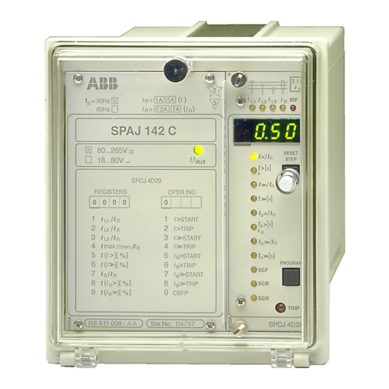
- Page 1 SPAJ 142 C Overcurrent and earth-fault relay User´s manual and Technical description > n = 50Hz 60Hz 0.2A SPAJ 142 C 80...265V ~ – RESET > STEP 18...80V – > SPCJ 4D29 >> REGISTERS OPER.IND. >> 0 0 0 0 >...
-
Page 2: Table Of Contents
Spare parts ........................13 Dimensions and instructions for mounting ..............14 Ordering information ....................15 The complete manual for the relay SPAJ 142 C contains the following partial manuals: General relay description 1MRS 750873-MUM EN General characteristics of D-type relay modules... -
Page 3: Description Of Operation
Remote reset, remote setting control or Start 2 blocking input for the different current stages Circuit breaker failure protection Blocking or 51BF reset Serial I/O Serial communication port Fig. 1. Protective functions of the overcurrent and earth-fault relay SPAJ 142 C. -
Page 4: Connection Diagram
SGR3/7 SGR3/8 SGR1/1 SGR1/3 SGR1/5 SGR1/7 SGR2/1 SGR2/3 SGR2/5 SGR2/7 SGR2/2 SGR2/4 SGR2/6 SGR2/8 SGR1/2 SGR1/4 SGR1/6 SGR1/8 SPA-ZC_ Fig. 2. Connection diagram for the combined overcurrent and earth-fault relay SPAJ 142 C with all the relay matrix switchgroups shown. - Page 5 T1…T8 Starting and tripping indications SERIAL PORT Serial communication interface SPA-ZC_ Bus connection module Rx/Tx Receiver bus terminal (Rx) and transmitter bus terminal (Tx) of the bus connection module = 63 Fig. 3. Rear view of relay SPAJ 142 C.
-
Page 6: Connections
The three phase-currents of the overcurrent pro- the control signals of the output relays B and C Connections tection are connected to terminals 1-2, 4-5 and identical. Normally the output relays B and C 7-8, when the rated current of the secondary are given such a configuration that low-set and circuits is I = 5 A. -
Page 7: Control Signals Between The Modules
SGB / 8 SPCJ 4D29 RELAY RESET Fig. 4. Control signals between the modules of the overcurrent and earth-fault relay SPAJ 142 C. The functions of the blocking and starting sig- of the measuring relay module. The functions nals are selected with the switches of switch- of the different switches are explained in the groups SGF, SGB and SGR. -
Page 8: Operation Indicators
When the protective stage resets, the red indi- n = 50Hz cator remains alight. 60Hz 0.2A SPAJ 142 C B) If the display is dark when one of the pro- 80...265V ~ – RESET tective stages I>, I>>, I > or I >>... -
Page 9: Power Supply And Output Relay Module
To be able to operate the relay needs a secured panel. The primary side of the power supply Power supply auxiliary voltage supply. The power supply mod- module is protected with a fuse, F1, located on and output ule forms the voltages required by the measur- the PCB of the module. -
Page 10: Technical Data (Modified 2002-04)
Technical data Energizing inputs (modified 2002-04) Rated current I Overcurrent unit Earth-fault unit 0.2 A Thermal withstand capability - continuously 1.5 A 20 A - for 1 s 50 A 100 A 500 A Dynamic current withstand, half-wave value 100 A 250 A 1250 A Input impedance... - Page 11 Overcurrent unit of SPCJ 4D29 Low-set overcurrent stage I > Setting range 0.5...5.0 x I Selectable modes of operation - definite time operation - operating time t> 0.05...300 s - inverse definite minimum time (IDMT) mode of operation as per IEC 60255-3 and BS 142 Extremely inverse Very inverse Normal inverse...
- Page 12 Data transmission Transmission mode Fibre optic serial bus Data code ASCII Selectable data transfer rates 4800 or 9600 Bd Fibre optic bus connection modules with integral power unit - for plastic core cables SPA-ZC 17 BB - for glass fibre cables SPA-ZC 17 MM Fibre optic bus connection modules which are powered from the host relay...
-
Page 13: Spare Parts
When the protective relay is operating under On request, the relay can be given a special treat- Maintenance the conditions specified in the section "Techni- ment for the protection of the printed circuit and repair cal data", the relay is practically maintenance- boards against stress on materials, caused by free. - Page 14 The relay is housed in a normally flush-mounted The relay case is complete with a hinged Dimensions for case. The relay can also be arranged for semi- gasketed, clear, UV-stabilized polycarbonate mounting flush mounting with the use of a 40 mm, 80 mm cover with a sealable fastening screw.
-
Page 15: Ordering Information
- Bus connection module SPA-ZC 21 BB - Fibre-optic cable SPA-ZF AA5, 2 pces - Fibre-optic cable SPA-ZF AA20, 5 pces Ordering numbers for SPAJ 142 C Type designation Name Order number SPAJ 142 C Combined overcurrent and RS 611 008 - AA, -CA, -DA, -FA... - Page 17 General characteristics of D-type relay modules User´s manual and Technical description 3 > Relay symbol Fastening screw Self-supervision alarm indicator Indicators for measured (Internal Relay Fault) quantities Display, 1 + 3 digits RESET > STEP t [ ] > Reset / Step push-button >>...
- Page 18 1MRS 750066-MUM EN General characteristics Issued 95-04-12 of D type relay modules Version A (replaces 34 SPC 3 EN1) Checked JH Approved TK Data subject to change without notice Front panel lay-out ......................1 Contents Control push buttons ..................... 3 Display ...........................
-
Page 19: Display
The front panel of the relay module contains certain position in the main menu to the corre- Control two push buttons. The RESET / STEP push sponding submenu, for entering the setting push-buttons button is used for resetting operation indicators mode of a certain parameter and together with and for stepping forward or backward in the the STEP push button for storing the set values. -
Page 20: Settings
Part of the settings and the selections of the Selector switch- operation characteristic of the relay modules in Switch No Pos. Weigth Value groups SGF, SGB various applications are made with the selector and SGR switchgroups SG_ . The switchgroups are soft- ware based and thus not physically to be found in the hardware of the relay module. -
Page 21: Setting Mode
NOTE! During any local man-machine com- any doubt about the settings of the module to be munication over the push buttons and the dis- inserted, the setting values should be read using play on the front panel a five minute time-out a spare relay unit or with the relay trip circuits function is active. - Page 22 MAIN MENU SUBMENUS STEP 0.5 s PROGRAM 1 s Normal status, display off Current on phase L1 Current on phase L2 Current on phase L3 REV. STEP 0.5 s FWD. STEP 1 s Neutral current Io SUBMENUS Second setting Main setting Actual start value I>...
- Page 23 Example 1 Operation in the setting mode. Manual setting for the main setting is 0.80 x I and for the of the main setting of the start current value I> second setting 1.00 x I . The desired main start of an overcurrent relay module.
- Page 24 RESET STEP Set the digit with the STEP push button. 1 1. 0 5 PROGRAM Press the PROGRAM push button to make the decimal point flash. 1 1. 0 5 RESET STEP If needed, move the decimal point with the STEP push button.
- Page 25 Example 2 Operation in the setting mode. Manual setting SGF1/1and SGF1/3 are to be set in position 1. of the main setting of the checksum for the This means that a checksum of 005 should be switchgroup SGF1 of a relay module. The initial the final result.
- Page 26 RESET STEP The switch position is altered to the desired position 1 by pressing the STEP push button once. PROGRAM Using the same procedure the switches SGF 1/ 5 x 1 s 4...8 are called up and, according to the exam- ple, left in position 0.
- Page 27 The parameter values measured at the moment Submenu 2 of register A contains a bus commu- Recorded when a fault occurs or at the trip instant are nication monitor for the SPAbus. If the protec- information recorded in the registers. The recorded data, tion relay, which contains the relay module, is except for some parameters, are set to zero by linked to a system including a contol data...
-
Page 28: Trip Test Function
Register 0 also provides access to a trip test The selected starting or tripping is activated by Trip test function function, which allows the output signals of the simultaneous pressing of the push buttons relay module to be activated one by one. If the STEP and PROGRAM. - Page 29 Example 3 Trip test function. Forced activation of the outputs. Step forward on the display to register 0. RESET STEP n x 1 s 0 0 0 0 Press the PROGRAM push button for about 3 > five seconds until the three green digits to the right.
- Page 30 To proceed to the next position press the PRO- 3 > GRAM push button for about 1 second until the indicator of the second setting starts flash- 0 0 0 0 ing. RESET > STEP PROGRAM t [ ] > >>...
-
Page 31: Operation Indicators
A relay module is provided with a multiple of indicator is reset by means of the RESET push Operation separate operation stages, each with its own button of the relay module. An unreset opera- indication operation indicator shown on the display and a tion indicator does not affect the function of the common trip indicator on the lower part of the protection relay module. - Page 33 SPCJ 4D29 Overcurrent and earth-fault relay module User´s manual and Technical description > RESET > STEP > >> >> o > o > >> >> PROGRAM TRIP SPCJ 4D29...
-
Page 34: Fault Codes
SPCJ 4D29 1MRS 750119-MUM EN Issued 1996-06-17 Combined overcurrent Modified 2002-05-15 Version C (replaces 34 SPCJ 8 EN1) and earth-fault relay Checked MK Approved OL module Data subject to change without notice Features .......................... 2 Contents Description of function ....................3 Block diagram ......................... -
Page 35: Description Of Function
The phase overcurrent unit of the relay module Note! Description of SPCJ 4D29 is designed for single-phase, two- The operation of the low-set stage based on function phase or three-phase overcurrent protection. It inverse time characteristic will be blocked by includes two overcurrent stages, i.e. - Page 36 Earth-fault unit The non-directional earth-fault unit of the relay range, 0.05...300 s. When the inverse time module SPCJ 4D29 is a single-pole earth-fault operation characteristic (IDMT) is selected, four unit. It contains two earth-fault stages, i.e. a internationally standardized and two comple- low-set earth-fault stage I >...
-
Page 37: Block Diagram
Block diagram SGR3 / 1 SGR1 / 1 50 ms SGR3 / 2 SGR2 / 1 I> t>, k SGR2 / 2 SGR1 / 2 SGR3 / 3 SGF1 / 1 RESET+ SGR1 / 3 SGB / 6 SGF1 / 2 SGB / 1 SGF2 / 7 SGF1 / 3... -
Page 38: Front Panel
Front panel > Indicators for the measured phase currents I and the residual current I RESET Indicator for the start current of the I> stage > STEP Indicator for the operate time t> or time multiplier k > of the I> stage Indicator for the start current of the I>>... -
Page 39: Start And Operation Indicators
Both overcurrent stages have their own start has operated. The start or operation indicators Start and indicators and operation indicators shown as are reset by pushing the RESET push-button. operation figures on the digital display. Further, all the The function of the relay module is not affected indicators protection stages share a common red LED by an unreset indicator. -
Page 40: Settings
The setting values are shown by the right-most symbol of the setting quantity shows the quan- Settings three digits of the display. When lit, the LED tity currently being displayed. indicators on the front panel adjacent to the I>/I Start current of the I> stage as a multiple of the rated current of the used energizing input. -
Page 41: Selector Switches
Additional functions required in various appli- groups are set. Under normal service conditions Selector switches cations are selected with switchgroups SGF, only the checksums are shown. Switchgroups SGB and SGR indicated on the front panel. The SGF2, SGR2 and SGR3 are found in the sub- numbering of the switches, 1...8, and the switch menus of the main menus of switchgroups SGF positions 0 and 1 are shown when the switch-... - Page 42 Function switch- Switch Function group SGF2 SGF2/1 Switches SGF2/1...4 are used for selecting the operation characteristic of the start SGF2/2 indicators of the different stages. When the switches are in position 0 the start signals SGF2/3 are all automatically reset when the fault is cleared. To give the indicator of a stage the SGF2/4 hand reset mode of operation, the corresponding switch is set in position 1: SGF2/1 = 1 equals manual reset mode for the start indication of stage I>...
- Page 43 Blocking or control Switch Function signal configuration switchgroup SGB SGB/1 Switches SGB/1...4 are used for routing an external blocking signal BS to one or more SGB/2 of the protection stages of the relay module. When the switches all are in position 0 SGB/3 no stage is blocked.
- Page 44 Output relay matrix SGR1 The switches of switchgroup SGR1 are used to select the start and operate signals switchgroups SGR1, to be routed to outputs SS1 and TS2. SGR2 and SGR3 SGR2 The switches of switchgroup SGR2 are used for routing the operate signals of the protection stages to the outputs SS2 and SS3.
-
Page 45: Measured Data
Switch Function Factory Checksum number setting value SGR3/1 When SGR3/1 = 1, the start signal of the I> stage is routed to TS1 SGR3/2 When SGR3/2 = 1, the trip signal of the I> stage is routed to TS1 SGR3/3 When SGR3/3 = 1, the start signal of the I>> stage is routed to TS1 SGR3/4 When SGR3/4 = 1, the trip signal of the I>>... -
Page 46: Recorded Information
The left-most red digit shows the address of the The // symbol in the text indicates that the item Recorded register and the right-most three digits the re- following the symbol is found in a submenu. information corded value. Register/ Recorded information STEP Phase current I displayed as a multiple of the rated current of the used input of the... - Page 47 Register/ Recorded information STEP Display of blocking signals and other external control signals. The right-most digit indicates the state of the blocking input of the module. The following states may be indicated: 0 = no blocking signal 1 = blocking or control signal BS active. The function of the external control signal on the relay unit is determined by the settings of switchgroup SGB From register "0"...
-
Page 48: Menu And Register Chart
Menu and register chart MAIN MENU SUBMENUS STEP 0.5 s PROGRAM 1 s Normal status, display off Current on phase L1 Current on phase L2 Current on phase L3 REV. STEP 0.5 s FWD. STEP 1 s Neutral current Io SUBMENUS Second setting Main setting... - Page 49 The procedures for entering a submenu or a described in detail in the manual "General char- setting mode and the method of performing the acteristics of D type relay modules". A short settings and the use of the TEST mode are form guide to the operations is shown below.
-
Page 50: Time/Current Characteristic (Modified 2002-05)
SGF1/6...8 for the earth-fault stage I > sets, named RI type and RXIDG type, accord- (see chapter "Selector switches", page 7). ing to ABB standards. IDMT Four standard curves named extremely inverse, The slope of the time/current curve sets is deter- mined by the constants α... - Page 51 RI-type The RI-type characteristic is a special character- where characteristic istic used mainly in combination with existing t = operate time in seconds mechanical relays. The characteristic is based on k = time multiplier the following mathematical expression: I = measured phase current I>...
- Page 52 0.09 0.08 0.07 0.06 0.05 0.04 0.05 0.03 0.02 6 7 8 9 10 20 I/I> Fig. 3. Extremely inverse-time characteristics of the overcurrent and earth-fault unit SPCJ 4D29.
- Page 53 0.09 0.08 0.07 0.06 0.05 0.05 0.04 0.03 0.02 6 7 8 9 10 20 I/I> Fig. 4. Very inverse-time characteristics of the overcurrent and earth-fault unit SPCJ 4D29.
- Page 54 0.05 0.09 0.08 0.07 0.06 0.05 0.04 0.03 0.02 7 8 9 10 20 I/I> Fig. 5. Normal inverse-time characteristics of the overcurrent and earth-fault unit SPCJ 4D29.
- Page 55 0.05 I/I> 7 8 9 Fig. 6. Long-time inverse-time characteristics of the overcurrent and earth-fault unit SPCJ 4D29.
- Page 56 0.05 0.09 0.08 0.07 0.06 0.05 0.04 0.03 0.02 6 7 8 9 10 20 I/I> Fig. 7. RI-type inverse-time characteristics of the overcurrent and earth-fault unit SPCJ 4D29.
- Page 57 0.09 0.08 0.07 0.06 0.05 0.04 0.4 0.5 0.05 0.03 0.02 7 8 9 10 I/I> Fig. 8. RXIDG-type inverse-time characteristics of the overcurrent and earth-fault unit SPCJ 4D29.
-
Page 58: Technical Data
- Inverse time characteristic acc. to BS 142 and IEC 60255-3 Extremely inverse Very inverse Normal inverse Long-time inverse - special characteristic acc. to ABB standards RI-type inverse RXIDG-type inverse - time multiplier k 0.05...1.00 Reset time, typ. 40 ms Retardation time <30 ms... - Page 59 High-set earth-fault stage I >> or ∞, infinite Start current I >> 0.1...10.0 x I Start time, typ. 40 ms Operate time 0.05...300 s Reset time, typ. 40 ms Drop-off/pick-up ratio, typ. 0.98 ±2% of set value or ±25 ms Operate time accuracy ±3% of set value Operation accuracy...
- Page 60 Code Event Weight factor Default value of the factor Starting of stage I > Resetting of starting of stage I > Operation of stage I > Resetting of operation of stage I > Starting of I >> stage Resetting of starting of stage I >>...
- Page 61 Data to be trans- In addition to the spontaneous data transfer the All the data are available in channel 0. ferred via the fibre- SPA bus allows reading of all input values (I- optic serial bus values), setting values (S-values), information R = data to be read from the unit recorded in the memory (V-values), and some W = data to be written to the unit...
- Page 62 Data Code Data Values direction Memorized I> start signal 0 = signal not active 1 = signal active Memorized I> operate signal 0 = signal not active 1 = signal active Memorized I>> start signal 0 = signal not active 1 = signal active Memorized I>>...
- Page 63 Data Code Data Values direction MAIN SETTING VALUES Start current of stage I>, R, W (P) 0.5...5.0 x I main setting Operate time or time multiplier R, W (P) 0.05...300 s of stage I>, main setting 0.05…1.0 Start current of stage I>>, R, W (P) 0.5...40.0 x I main setting...
- Page 64 Data Code Data Values direction Checksum of switchgroup SGF1, R, W (P) 0...255 second setting Checksum of switchgroup SGF2, R, W (P) 0...255 second setting Checksum of switchgroup SGB, R, W (P) 0...255 second setting Checksum of switchgroup SGR1, R, W (P) 0...255 second setting Checksum of switchgroup SGR2,...
- Page 65 Data Code Data Values direction Remote control of settings V150 R, W 0 = main settings activated 1 = second settings activated, see chapter "Description of function" Event mask word for V155 R, W 0...255, see chapter overcurrent events "Event codes" Event mask word for V156 R, W...
- Page 66 Shortly after the internal self-supervision system indicates the fault type. When a fault code Fault codes has detected a permanent relay fault, the red IRF appears on the display, the code number should indicator is lit and the output relay of the self- be recorded and given to the authorized repair supervision system operates.
- Page 68 ABB Oy Distribution Automation P.O.Box 699 FI-65101 Vaasa FINLAND Tel. +358 (0)10 22 11 Fax.+358 (0)10 22 41094 www.abb.com/substationautomation...