ABB REL650 Applications Manual
Line distance protection relion 650 series
Hide thumbs
Also See for REL650:
- Technical manual (942 pages) ,
- Commissioning manual (208 pages) ,
- Product manual (118 pages)
Table of Contents
Advertisement
Advertisement
Table of Contents

Related Manuals for ABB REL650


Summary of Contents for ABB REL650
- Page 1 ® Relion 650 series Line distance protection REL650 ANSI Application manual...
- Page 3 Document ID: 1MRK 506 334-UUS Issued: October 2016 Revision: A Product version: 1.3 © Copyright 2013 ABB. All rights reserved...
- Page 4 Copyright This document and parts thereof must not be reproduced or copied without written permission from ABB, and the contents thereof must not be imparted to a third party, nor used for any unauthorized purpose. The software and hardware described in this document is furnished under a license and may be used or disclosed only in accordance with the terms of such license.
- Page 5 This document has been carefully checked by ABB but deviations cannot be completely ruled out. In case any errors are detected, the reader is kindly requested to notify the manufacturer.
- Page 6 (EMC Directive 2004/108/EC) and concerning electrical equipment for use within specified voltage limits (Low-voltage directive 2006/95/EC). This conformity is the result of tests conducted by ABB in accordance with the product standard EN 60255-26 for the EMC directive, and with the product standards EN 60255-1 and EN 60255-27 for the low voltage directive.
-
Page 7: Table Of Contents
REL650 application examples..............38 Adaptation to different applications........... 38 Functionality table................38 Section 3 REL650 setting examples........... 41 Setting example for a two-ended overhead transmission line in a solidly grounded network................ 41 Calculating general settings for analogue TRM inputs 4I 1I 5U..42 Calculating settings for Global base values for setting function GBASVAL..................43... - Page 8 Table of contents Calculating settings for phase selection with load encroachment FDPSPDIS (21)................. 55 Faulty phase identification with load encroachment for mho FMPSPDIS..................57 Calculating settings for scheme communication logic with delta based blocking scheme signal transmit ZCPSCH (85)......57 Principles for over-reach permissive communication logic...58 Principles for under-reach permissive communication logic..59 Principle for blocking scheme............60 Principle for delta blocking scheme..........
- Page 9 Table of contents Introduction..................... 89 Setting guidelines................... 89 Setting of the phase reference channel..........89 Relationships between setting parameter Base Current, CT rated primary current and minimum pickup of a protection IED....90 Setting of current channels..............90 Example 1..................91 Example 2..................92 Examples on how to connect, configure and set CT inputs for most commonly used CT connections..........94 Example on how to connect a wye connected three-phase CT set to the IED................95...
- Page 10 Table of contents Load encroachment..............127 Setting guidelines................129 General..................129 Setting of characteristic.............. 130 Quadrilateral characteristics............136 Mho characteristics..............138 Phase selection with load enchroachment, quadrilateral characteristic FDPSPDIS (21).............. 139 Identification..................139 Application..................139 Setting guidelines................139 Load encroachment characteristics..........139 Resistive reach with load encroachment characteristic....145 Minimum operate currents............146 Faulty phase identification with load enchroachment for mho FMPSPDIS (21)..................
- Page 11 Table of contents Section 7 Current protection..............169 Instantaneous phase overcurrent protection 3-phase output PHPIOC (50)..................169 Identification..................169 Application..................169 Setting guidelines................170 Meshed network without parallel line..........170 Meshed network with parallel line..........172 Instantaneous phase overcurrent protection phase segregated output SPTPIOC (50)................174 Identification..................
- Page 12 Table of contents Common settings for all steps............ 206 2nd harmonic restrain..............208 Line application example1............208 Sensitive directional residual overcurrent and power protection SDEPSDE (67N)...................214 Identification..................214 Application..................214 Setting guidelines................216 Time delayed 2-step undercurrent protection UC2PTUC (37)....224 Identification..................224 Application..................
- Page 13 Table of contents Application..................241 Directional overpower protection GOPPDOP (32)......243 Identification................244 Setting guidelines............... 244 Directional underpower protection GUPPDUP (37)......248 Identification................248 Setting guidelines............... 248 Negative sequence based overcurrent function DNSPTOC (46)..252 Identification..................252 Application..................252 Setting guidelines................252 Section 8 Voltage protection.............
- Page 14 Table of contents Section 9 Frequency protection............269 Underfrequency protection SAPTUF (81)..........269 Identification..................269 Application..................269 Setting guidelines................270 Overfrequency protection SAPTOF (81)..........270 Identification..................271 Application..................271 Setting guidelines................271 Rate-of-change frequency protection SAPFRC (81)......272 Identification..................272 Application..................272 Setting guidelines................273 Section 10 Secondary system supervision..........275 Current circuit supervision CCSRDIF (87)..........275 Identification..................
- Page 15 Table of contents Energizing check................ 290 Voltage selection................ 291 External fuse failure..............292 Application examples...............293 Single circuit breaker with single busbar........294 Single circuit breaker with double busbar, external voltage selection..................295 Single circuit breaker with double busbar, internal voltage selection..................296 Double circuit breaker..............297 Setting guidelines................
- Page 16 Table of contents Blocking of the autorecloser............322 Control of the auto-reclosing open time for shot 1......323 Long trip signal................323 Reclosing programs..............323 FirstShot=3ph (normal setting for a single 3 phase shot)... 323 3-phase reclosing, one to five shots according to setting NoOfShots..................
- Page 17 Table of contents Interlocking for bus-section breaker A1A2_BS (3)......355 Application.................. 355 Signals from all feeders.............. 356 Configuration setting..............359 Interlocking for bus-section disconnector A1A2_DC (3)....360 Application.................. 360 Signals in single breaker arrangement........360 Signals in double-breaker arrangement........364 Signals in breaker and a half arrangement.........366 Interlocking for bus-coupler bay ABC_BC (3)........
- Page 18 Table of contents Identification..................387 Application..................388 Setting guidelines................388 Single point generic control 8 signals SPC8GGIO....... 388 Identification..................388 Application..................388 Setting guidelines................388 Automation bits AUTOBITS..............389 Identification..................389 Application..................389 Setting guidelines................389 Section 12 Scheme communication............ 391 Scheme communication logic with delta based blocking scheme signal transmit ZCPSCH(85)..............
- Page 19 Table of contents Weak-end infeed logic..............403 Setting guidelines................404 Current reverse logic..............404 Weak-end infeed logic..............405 Local acceleration logic ZCLCPLAL............. 405 Identification..................405 Application..................405 Setting guidelines................406 Scheme communication logic for residual overcurrent protection ECPSCH (85)..................407 Identification..................
- Page 20 Table of contents Application..................418 Setting guidelines................419 Configurable logic blocks..............419 Identification..................419 Application..................420 Configuration................421 Fixed signals FXDSIGN................422 Identification..................422 Application..................422 Boolean 16 to integer conversion B16I..........423 Identification..................423 Application..................423 Setting guidelines................424 Boolean 16 to integer conversion with logic node representation B16IFCVI....................
- Page 21 Table of contents Setting guidelines................428 IEC61850 generic communication I/O functions MVGGIO....428 Identification..................428 Application..................428 Setting guidelines................428 Measurements..................429 Identification..................429 Application..................429 Setting guidelines................431 Setting examples................434 Measurement function application for a 380kV OHL....435 Event counter CNTGGIO..............437 Identification..................
- Page 22 Table of contents Identification..................450 Application..................450 Insulation liquid monitoring function SSIML (71)........451 Identification..................451 Application..................451 Circuit breaker condition monitoring SSCBR........451 Identification..................451 Application..................451 Section 15 Metering................455 Pulse counter PCGGIO................ 455 Identification..................455 Application..................455 Setting guidelines................455 Energy calculation and demand handling EPTMMTR......
- Page 23 Table of contents Application..................473 Setting guidelines................474 Test mode functionality TESTMODE............474 Identification..................474 Application..................474 Setting guidelines................475 Change lock CHNGLCK............... 475 Identification..................475 Application..................475 Setting guidelines................476 IED identifiers TERMINALID..............476 Identification..................476 Application..................476 Customer specific settings............476 Product information PRODINF.............
- Page 24 Table of contents Denial of service................... 487 Identification..................487 Application..................487 Setting guidelines................487 Section 18 Requirements..............489 Current transformer requirements............489 Current transformer classification............ 489 Conditions..................490 Fault current..................491 Secondary wire resistance and additional load....... 491 General current transformer requirements........492 Rated equivalent secondary e.m.f.
-
Page 25: Section 1 Introduction
Section 1 1MRK 506 334-UUS A Introduction Section 1 Introduction This manual The application manual contains application descriptions and setting guidelines sorted per function. The manual can be used to find out when and for what purpose a typical protection function can be used. The manual can also provides assistance for calculating settings. -
Page 26: Product Documentation
Section 1 1MRK 506 334-UUS A Introduction Product documentation 1.3.1 Product documentation set Engineering manual Installation manual Commissioning manual Operation manual Application manual Technical manual Communication protocol manual IEC07000220-3-en.vsd IEC07000220 V3 EN Figure 1: The intended use of manuals throughout the product lifecycle The engineering manual contains instructions on how to engineer the IEDs using the various tools available within the PCM600 software. -
Page 27: Document Revision History
Document revision history Document revision/date History -/March 2013 First release A/October 2016 Minor corrections made 1.3.3 Related documents Documents related to REL650 Identity number Application manual 1MRK 506 334-UUS Technical manual 1MRK 506 335-UUS Commissioning manual 1MRK 506 336-UUS Product Guide... -
Page 28: Symbols And Conventions
Section 1 1MRK 506 334-UUS A Introduction 650 series manuals Identity number Communication protocol manual, DNP 3.0 1MRK 511 280-UUS Communication protocol manual, IEC 61850–8–1 1MRK 511 281-UUS Communication protocol manual, IEC 60870-5-103 1MRK 511 282-UUS Cyber Security deployment guidelines 1MRK 511 285-UUS Point list manual, DNP 3.0 1MRK 511 283-UUS... -
Page 29: Document Conventions
Section 1 1MRK 506 334-UUS A Introduction The tip icon indicates advice on, for example, how to design your project or how to use a certain function. Although warning hazards are related to personal injury, it is necessary to understand that under certain operational conditions, operation of damaged equipment may result in degraded process performance leading to personal injury or death. -
Page 31: Section 2 Application
Application REL650 application REL650 is used for the protection, control and monitoring of overhead lines and cables in solidly or impedance grounded networks. The IED can be used up to the high voltage levels. It is suitable for the protection of heavily loaded lines and multi-terminal lines where the requirement for fast one- and/or three-pole tripping is wanted. - Page 32 Section 2 1MRK 506 334-UUS A Application • Five zone distance protection with quadrilateral and mho characteristic, three-phase tripping (A01A) • Five zone distance protection with quadrilateral and mho characteristic, double breaker, three-phase tripping (B01A) • Five zone distance protection with quadrilateral and mho characteristic, single-pole tripping (A11A) The packages are configured and they usually need only a simple customization.
- Page 33 Section 2 1MRK 506 334-UUS A Application 132 kV Bus BUS1 REL650 A01A – 5 Distance Zones, Single Breaker 10AI (4I+1I+5U) BUS2 132kV/110V 132kV/110V 0->1 1->0 SYNC 289G SMB RREC SMP PTRC SES RSYN Meter. Meter. C MMXU C MSQI...
- Page 34 Section 2 1MRK 506 334-UUS A Application REL650 B01A – 5 Distance Zones, Double Breaker Ring Bus 10AI (4I+1I+5U) + 10AI (4I+1I+5U) 0->1 1->0 SYNC SMB RREC SMP PTRC SES RSYN 132kV/ 0->1 1->0 SYNC 110V SMB RREC SMP PTRC...
- Page 35 Section 2 1MRK 506 334-UUS A Application 132 kV Bus BUS1 REL650A11A-5 DistanceZones, 1PH/3 PH Tripping Single Breaker 10AI(4I+1I+5U) BUS2 132kV/110V 132kV/110V 289G 0->1 1->0 25 SYNC STB RREC STP PTRC SES RSYN Meter. Meter. 389G C MMXU C MSQI SDD RFUF 52PD I>...
-
Page 36: Available Functions
Section 2 1MRK 506 334-UUS A Application Available functions 2.2.1 Main protection functions IEC 61850 or ANSI Function description Line Distance Function name Impedance protection ZQMPDIS Five zone distance protection, quadrilateral and mho characteristic FDPSPDIS Phase selection with load enchroachment, quadrilateral characteristic FMPSPDIS Faulty phase identification with load enchroachment for mho... - Page 37 Section 2 1MRK 506 334-UUS A Application IEC 61850 or ANSI Function description Line Distance Function name EF4PTOC 51N/67N Four step residual overcurrent protection, zero/ 0–1 negative sequence direction SDEPSDE Sensitive directional residual overcurrent and power 0–1 protection UC2PTUC Time delayed 2-step undercurrent protection 0–1 LCPTTR Thermal overload protection, one time constant,...
-
Page 38: Control And Monitoring Functions
Section 2 1MRK 506 334-UUS A Application 2.2.3 Control and monitoring functions IEC 61850 or Function ANSI Function description Line Distance name Control SESRSYN Synchrocheck, energizing check, and 0–2 synchronizing SMBRREC Autorecloser for 3–phase operation 0–2 STBRREC Autorecloser for 1/3–phase operation 0–1 SLGGIO Logic Rotating Switch for function selection and... - Page 39 Section 2 1MRK 506 334-UUS A Application IEC 61850 or Function ANSI Function description Line Distance name DB_LINE Interlocking for double CB bay ABC_LINE Interlocking for line bay AB_TRAFO Interlocking for transformer bay SCSWI Switch controller QCBAY Bay control LOCREM Handling of LR-switch positions LOCREMCTRL LHMI control of Permitted Source To Operate...
- Page 40 Section 2 1MRK 506 334-UUS A Application IEC 61850 or Function ANSI Function description Line Distance name XORQT Configurable logic blocks Q/T 0–40 SRMEMORYQT Configurable logic blocks Q/T 0–40 RSMEMORYQT Configurable logic blocks Q/T 0–40 TIMERSETQT Configurable logic blocks Q/T 0–40 PULSETIMERQT Configurable logic blocks Q/T...
- Page 41 Section 2 1MRK 506 334-UUS A Application IEC 61850 or Function ANSI Function description Line Distance name L4UFCNT Event counter with limit supervision DRPRDRE Disturbance report AnRADR Analog input signals BnRBDR Binary input signals SPGGIO IEC 61850 generic communication I/O functions SP16GGIO IEC 61850 generic communication I/O functions 16 inputs...
-
Page 42: Station Communication
Section 2 1MRK 506 334-UUS A Application 2.2.4 Station communication IEC 61850 or Function ANSI Function description Line Distance name Station communication IEC61850-8-1 IEC 61850 communication protocol DNPGEN DNP3.0 communication general protocol RS485DNP DNP3.0 for RS-485 communication protocol CH1TCP DNP3.0 for TCP/IP communication protocol CH2TCP DNP3.0 for TCP/IP communication protocol CH3TCP... -
Page 43: Basic Ied Functions
Section 2 1MRK 506 334-UUS A Application IEC 61850 or Function ANSI Function description Line Distance name ACTIVLOG Activity logging parameters SECALARM Component for mapping security events on protocols such as DNP3 and IEC103 AGSAL Generic security application component GOOSEDPRCV GOOSE function block to receive a double point value GOOSEINTRCV... -
Page 44: Rel650 Application Examples
DOSLAN1 Denial of service, frame rate control for LAN1A and LAN1B ports DOSSCKT Denial of service, socket flow control REL650 application examples 2.3.1 Adaptation to different applications The IED is provided with one pre-defined configuration to be used with quadrilateral distance protection characteristic. - Page 45 Section 2 1MRK 506 334-UUS A Application • Enabled: It is recommended to have the function activated in the application • Disabled: It is recommended to have the function deactivated in the application • Application dependent: The decision to have the function activated or not is dependent on the specific conditions in each case Application 1- 5 in table are according to application examples given in...
- Page 46 Section 2 1MRK 506 334-UUS A Application Function Application 1 Application 2 Application 3 Application 4 Application 5 Breaker failure protection, 3-phase activation and Enabled Enabled Enabled Enabled Enabled output CCRBRF (50BF) Pole discordance protection CCRPLD (52PD) Application Application Application Application Application dependent...
-
Page 47: Section 3 Rel650 Setting Examples
Section 3 1MRK 506 334-UUS A REL650 setting examples Section 3 REL650 setting examples Setting example for a two-ended overhead transmission line in a solidly grounded network The application example: a 138 kV line as shown in figure Z 1 = R 1 + jX 1... -
Page 48: Calculating General Settings For Analogue Trm Inputs 4I 1I 5U
Section 3 1MRK 506 334-UUS A REL650 setting examples Entity Value Low zero sequence source impedance at B j5 Ω CT ratio at A and B 1 000/1 A VT ratio at A and B Maximum power transfer on the line... -
Page 49: Calculating Settings For Global Base Values For Setting Function Gbasval
Section 3 1MRK 506 334-UUS A REL650 setting examples Set the primary and secondary values for current transformer input 1. 1.1. Set CT_WyePoint1 to ToObject (The CT secondary is grounded towards the protected line) 1.2. Set CTSec1 to 1 A (The rated secondary current of the CT) 1.3. -
Page 50: Calculating Settings For Five Zone Distance Protection, Quadrilateral And Mho Characteristic Zqmpdis (21)
Section 3 1MRK 506 334-UUS A REL650 setting examples needed in the Two-ended over-head transmission line in a solidly grounded network application. For line protection, set the parameters for the Global base values for settings functions according to instrument transformer primary rated values (recommended):... - Page 51 Section 3 1MRK 506 334-UUS A REL650 setting examples The function of the zones for the distance protection A can be seen in figure 6. Zone 4 Zone 3 Zone 2 Zone 1 Z 1 = R 1 + jX 1...
-
Page 52: Calculating General Settings
Section 3 1MRK 506 334-UUS A REL650 setting examples 3.1.3.1 Calculating general settings Set GlobalBaseSel to 1 Set LineAng to 81.9º The positive sequence impedance line angle for the protected line is calculated as æ ö æ ö ç ç... -
Page 53: Calculating Settings For Zone 1
Section 3 1MRK 506 334-UUS A REL650 setting examples Ð ° Ð ° line line × × Ð ° line (Equation 4) GUID-9625121F-6173-44E5-B4E1-751109679250 V1 EN Set CvtFltr to Enabled, if the protected line has CVT. This will prevent the overreaching effect of the CVT transients. - Page 54 Section 3 1MRK 506 334-UUS A REL650 setting examples Line impedance 85 % of Line impedance IEC09000410_1_en.vsd IEC09000410 V1 EN Figure 7: Line impedance diagram The setting Z1is calculated as: × × 1 0.85 0.85 2.5 17.5 15.0 Line posseq...
- Page 55 Section 3 1MRK 506 334-UUS A REL650 setting examples ph ph Ð - ° 84 8 17 5 ,Line ,Source (Equation 7) GUID-3662A0FC-7F22-4848-B102-B12D1E0E79F2-ANSI V1 EN where: 0+j10 ohms 1Source This gives the following arc resistance: 28700 » × = 5 2.0...
- Page 56 Section 3 1MRK 506 334-UUS A REL650 setting examples Each individual tower foot has a resistance to ground up to 100 Ω, as the soil has very high resistivity. The towers are however connected to each other via the shield wire at the top of the towers, grounded to every tower.
-
Page 57: Calculating Settings For Zone 2
Section 3 1MRK 506 334-UUS A REL650 setting examples Zone 1 phase to phase loop gives trip. Set time delays to trip. 9.1. Set tPPZ1 to 0.000 s. Zone 1 phase to phase loops gives instantaneous trip. 9.2. Set tPGZ1 to 0.000 s. - Page 58 Section 3 1MRK 506 334-UUS A REL650 setting examples £ × × 0.85 source B source A × × 0.85 source B 8 3.2 17.5 × × 17.5 0.85 10 48.0 (Equation 11) GUID-CD674B2B-8DA2-4614-A12E-0BE6E3EF7ACF V1 EN This corresponds to about 2.7 times the line reactance.
-
Page 59: Calculating Settings For Zone 3
Section 3 1MRK 506 334-UUS A REL650 setting examples Zone 2 phase to ground loop gives trip. Set OpModetPPZ2 to Enabled. Zone 2 phase to phase loop gives trip. Set time delays to trip. Zone 2 phase to ground loops gives trip 8.1. -
Page 60: Calculating Settings For Zone 4
Section 3 1MRK 506 334-UUS A REL650 setting examples The reactance of the longest line adjacent out from substation B is 20 Ω as shown in figure. The reactance of the transformer in substation B is 30 Ω (60 MVA transformer, 10 % short circuit voltage). -
Page 61: Fdpspdis (21)
Section 3 1MRK 506 334-UUS A REL650 setting examples Set DirModeZ4 to Reverse. Set MhoCharZ4 to Directional, if CharPGZ4 or CharPPZ4 is set to Mho. Set Z1 to 4.2 Ω Z1 = 0.85 · Z = 0.85 · 0.28 · 17.5 = 4.2 Ω... - Page 62 Section 3 1MRK 506 334-UUS A REL650 setting examples X1 ≥ 1.1 · X1 (Zone2) = 1.1 · 44.2 = 48.5 Ω 4.2. Set X0 to 140 Ω X0 ≥ 1.1 · X0 (Zone2) = 138.9 Ω Set the fault resistance reach (phase-phase) 5.1.
-
Page 63: Faulty Phase Identification With Load Encroachment For Mho Fmpspdis
Section 3 1MRK 506 334-UUS A REL650 setting examples 3.1.5 Faulty phase identification with load encroachment for mho FMPSPDIS The function is based of different principles to identify the fault type. The signals from the different fault identification algorithms are combined in selection logic. -
Page 64: Principles For Over-Reach Permissive Communication Logic
Section 3 1MRK 506 334-UUS A REL650 setting examples • Intertrip scheme • Permissive underreaching scheme • Permissive overreaching scheme • Blocking scheme • Delta blocking scheme As an example the setting guidelines for delta blocking scheme is given below:... -
Page 65: Principles For Under-Reach Permissive Communication Logic
Section 3 1MRK 506 334-UUS A REL650 setting examples A communication signal is sent (CS) if a fault is detected by zone 2 (overreach zone). When a communication signal is received (CR) zone 2 operates instantaneously. The logic is shown in figure 13. -
Page 66: Principle For Blocking Scheme
Section 3 1MRK 506 334-UUS A REL650 setting examples A communication signal is sent (CS) if a fault is detected by zone 1 (underreach zone). When a communication signal is received (CR) zone 2 operates instantaneously. The logic is shown in figure 15. - Page 67 Section 3 1MRK 506 334-UUS A REL650 setting examples Zone 4 ( reverse ) Zone 2 Zone 1 Z 1 = R 1 + jX 1 Z 0 = R 0 + jX0 Communication REL 650 REL 650 Zone 1...
-
Page 68: Principle For Delta Blocking Scheme
Section 3 1MRK 506 334-UUS A REL650 setting examples ZQMPDIS (21) Zone 1 TRIP Zone 1 PICKUP Trip Zone 2 TRIP Zone 2 PICKUP Receive signal ( CR) Reverse : Zone 4 TRIP Send signal (CS) Zone 4 PICKUP ANSI11000077_2_en.vsd... - Page 69 Section 3 1MRK 506 334-UUS A REL650 setting examples Delta based fault inception detection and forward fault inhibit Zone 2 Zone 1 Z 1 = R 1 + jX 1 Z 0 = R 0 + jX0 Communication REL 650...
-
Page 70: Calculating Setting For Current Reversal And Weak End Infeed Logic For Distance Protection Zcrwpsch (85)
Section 3 1MRK 506 334-UUS A REL650 setting examples The trip signal from zone2 in this case need not be delayed except in case where the transmission channel is slow. 3.1.7 Calculating setting for current reversal and weak end infeed... -
Page 71: Calculating Setting For Switch Into Fault Logic Voltage And Current Based Zcvpsof
Section 3 1MRK 506 334-UUS A REL650 setting examples • For an internal fault zone 2 in line end B will pick up and send a signal to line end A (CS). • If zone 4 (reverse) or none of the forward zones in line end A does not pick up the received signal from line end B (CR) will be sent back (echo). -
Page 72: Calculating Settings For Four Step Phase Overcurrent Protection
Section 3 1MRK 506 334-UUS A REL650 setting examples Default value Set UVPickup to 70 % of VBase Default value that must be lower than the voltage at normal operation Set tDuration to 0.020 s Default value for time delay of UI detection Set tSOTF to 1.0 s... -
Page 73: Calculating General Settings
Section 3 1MRK 506 334-UUS A REL650 setting examples The reach of phase overcurrent line protection is dependent of the operation state and the fault type. Therefore the setting must be based on fault calculations made for different faults, fault points and switching states in the network. Although it is possible to make hand calculations of the different faults it is recommended to use computer based fault calculations. -
Page 74: Calculating Settings For Step 1
Section 3 1MRK 506 334-UUS A REL650 setting examples 3.1.9.2 Calculating settings for step 1 Set Pickup1 to 490 % of IBase The calculations show the largest phase current I = 3.84 kA To assure selectivity the setting must fulfil: ⋅... -
Page 75: Calculating Settings For Step 3
Section 3 1MRK 506 334-UUS A REL650 setting examples The fault current fed to the protection shall be calculated for the fault points 3, 4, 5 and 6 (faults about 80 % out on the adjacent lines connected to the local and remote busbar). -
Page 76: Calculating Settings For Four Step Residual Overcurrent Protection Zero Or Negative Sequence Direction Ef4Ptoc(51N_67N)
Section 3 1MRK 506 334-UUS A REL650 setting examples source impedance at line end A should be maximized (minimum short circuit power) for this calculation. We get the phase current If = 0.46 kA ault7,8,min To assure that step 3 detects all short circuits on the adjacent lines out from the local busbar a phase-phase short circuit is applied at fault points 9 and 10. - Page 77 Section 3 1MRK 506 334-UUS A REL650 setting examples The four step residual overcurrent protection has the following purpose: • Fast and sensitive protection for ground-faults on the protected line. • Backup protection for ground-faults on the adjacent busbar in case the distance protection is unavailable (after fuse failure blocking) •...
-
Page 78: Calculating General Settings
Section 3 1MRK 506 334-UUS A REL650 setting examples The residual overcurrent protection in line end A is considered. See figure 22. The same principle can be used for the other line end. 3.1.10.1 Calculating general settings Set GlobalBaseSel to 1 The settings are made in primary values. -
Page 79: Calculating Settings For Step 2
Section 3 1MRK 506 334-UUS A REL650 setting examples where k is the transient overreach (due to fault current DC-component) of the overcurrent function. For the four step residual overcurrent function, k = 1.05. Set t1 to 0 s 3.1.10.3... -
Page 80: Calculating Settings For Step 4
Section 3 1MRK 506 334-UUS A REL650 setting examples = 4 000 A and we get 0BC,step1 × 4000 1060 2980 (Equation 25) GUID-F6D8356A-6802-4076-8240-0290B2C9C500 V1 EN This calculation is made for fault out on each of the lines out from the remote busbar. -
Page 81: Over-Reach Permissive Logic
Section 3 1MRK 506 334-UUS A REL650 setting examples • Power line carrier (PLC) • Microwave link (radio) • Optic fibre link There are the following alternatives for communication scheme: • Under-reach permissive logic • Over-reach permissive logic • Blocking scheme Set SchemeType to Permissive OR This corresponds to over-reach permissive scheme. -
Page 82: Under-Reach Permissive Logic
Section 3 1MRK 506 334-UUS A REL650 setting examples A communication signal is sent (CS) if a fault is detected by step 2 (3I >> overreach step). When a communication signal is received (CR) Step 2 (3I >>) operates instantaneously. - Page 83 Section 3 1MRK 506 334-UUS A REL650 setting examples Step 2- reach Step 1- reach Z 1 = R 1 + jX 1 Z 0 = R 0 + jX0 Communication REL 650 REL 650 Step 1- reach Step 2- reach ANSI11000115_2_en.vsd...
-
Page 84: Blocking Scheme
Section 3 1MRK 506 334-UUS A REL650 setting examples 3.1.11.3 Blocking scheme The principle of the logic can be explained as shown in figure 29. Step 4 ( reverse ) Step Step Z 1 = R 1 + jX 1... -
Page 85: Calculating Settings For Current Reversal And Weak-End Infeed Logic For Residual Overcurrent Protection Ecrwpsch (85)
Section 3 1MRK 506 334-UUS A REL650 setting examples EF4PTOC (51N_67N) Step 1 TRIP Step 1 PUST1 Trip Step 2 TRIP Step 2 PUST2 Receive signal (CR) Reverse : Step 4 TRIP Step 4 PUREV Send signal (CS) ANSI11000080_1_en.vsd ANSI11000080 V1 EN... - Page 86 Section 3 1MRK 506 334-UUS A REL650 setting examples Step 2- reach Step 1- reach Z 1 = R 1 + jX 1 Z 0 = R 0 + jX0 Communication REL 650 REL 650 Step 1- reach Step 2- reach ANSI11000115_2_en.vsd...
-
Page 87: Calculating Settings For Breaker Failure Protection 3-Phase Activation And Output Ccrbrf (50Bf)
Section 3 1MRK 506 334-UUS A REL650 setting examples Set WEI to Echo & Trip This echoes CR signal as well as trip locally. Set tPickUpWEI to 0.01 s Shortest duration of CR signal. Set UPP< to lower than the lowest possible phase-to-phase voltage at non-faulted operation. -
Page 88: Setting Example For A Two-Ended Over-Head Transmission Line In A High Impedance Network
Section 3 1MRK 506 334-UUS A REL650 setting examples Pickup_N should be set lower than the smallest current to be detected by the most sensitive step of the residual ovecurrent protection which is 100 A. Set t1 to 0 s Re-tip time delay: t1 Set t2 to 0.17 s... -
Page 89: Calculating Settings For Phase Preference Logic Pplphiz
Section 3 1MRK 506 334-UUS A REL650 setting examples ended over-head transmission line in a high impedance network application, except the phase preference logic and sensitive directional residual overcurrent protection which are used in high impedance networks. 3.2.1 Calculating settings for phase preference logic PPLPHIZ The phase preference logic is only to be used if it is allowed to operate the network with single phase-to-ground fault. - Page 90 Section 3 1MRK 506 334-UUS A REL650 setting examples Set OperMode to 1231c When a cross-country fault has been detected the trip is made according to a chosen priority: OperMode. This setting shall be identical for all distance protections in the system. In this case a cyclic order is used: A–...
-
Page 91: Calculating Settings For Sensitive Directional Residual Overcurrent Protection Sdepsde 67N
Section 3 1MRK 506 334-UUS A REL650 setting examples 0line REL 650 Phase-ground fault REL 650 ANSI11000119_1_en.vsd ANSI11000119 V1 EN Figure 34: Single phase-to-ground fault Set tVN to 0.001 s Setting tVN gives the pick-up delay for residual voltage. The default value 0.001 s is proposed. -
Page 92: Application Manual
Section 3 1MRK 506 334-UUS A REL650 setting examples capacitance between the phase conductors and ground and the impedance of equipment connected between the transformer neutral point and ground. In this network a Petersen coil parallel with a neutral point resistor is connected to the transformer neutral. The active ground fault current, that is, the residual current in phase with the residual voltage, is used for line fault detection. -
Page 93: Application Manual
Section 3 1MRK 506 334-UUS A REL650 setting examples The requirement in this network is that the ground fault protection shall have sensitivity so that ground faults with resistance up to 3 000 Ω shall be detected and cleared. The residual voltage at 3 000 Ω works out as:... -
Page 94: Application Manual
Section 3 1MRK 506 334-UUS A REL650 setting examples Use the setting INDirPU when OpModeSel is set to 3I0 and fi Use the setting SN_PU when OpModeSel is set to 3I03V0Cosfi Set TimeChar to IEC Def.Time The setting TimeChar gives the time characteristic of the sensitive residual overcurrent protection. -
Page 95: Section 4 Analog Inputs
Section 4 1MRK 506 334-UUS A Analog inputs Section 4 Analog inputs Introduction Analog input channels in the IED must be set properly in order to get correct measurement results and correct protection operations. For power measuring and all directional and differential functions the directions of the input currents must be defined in order to reflect the way the current transformers are installed/connected in the field ( primary and secondary connections ). -
Page 96: Relationships Between Setting Parameter Base Current, Ct Rated Primary Current And Minimum Pickup Of A Protection Ied
Section 4 1MRK 506 334-UUS A Analog inputs The phase reference does not work if the current channel is not available. For example, when the circuit breaker is opened and no current flows. Although the phase angle difference between the different phases is firm, the whole system appears to be rotating when the measurement functions are observed. -
Page 97: Example 1
Section 4 1MRK 506 334-UUS A Analog inputs A positive value of current, power, and so on (forward) means that the quantity has a direction towards the object. - A negative value of current, power, and so on (reverse) means a direction away from the object. See figure 35. Definition of direction Definition of direction for directional functions... -
Page 98: Example 2
Section 4 1MRK 506 334-UUS A Analog inputs Line Transformer Line Reverse Forward Definition of direction for directional functions Transformer protection Line protection Setting of current input: Setting of current input: Setting of current input: Set parameter Set parameter Set parameter CT_WyePoint with CT_WyePoint with CT_WyePoint with... - Page 99 Section 4 1MRK 506 334-UUS A Analog inputs ANSI05000460 V2 EN Application manual...
-
Page 100: Examples On How To Connect, Configure And Set Ct Inputs For Most Commonly Used Ct Connections
Section 4 1MRK 506 334-UUS A Analog inputs Transformer Line Reverse Forward Definition of direction for directional functions Transformer Line protection protection Setting of current input: Setting of current input: Setting of current input: Set parameter Set parameter Set parameter CT_WyePoint with CT_WyePoint with CT_WyePoint with... -
Page 101: Example On How To Connect A Wye Connected Three-Phase Ct Set To The Ied
Section 4 1MRK 506 334-UUS A Analog inputs (H2) (H1) S2 (X2) S1 (X1) S2 (X2) S1 (X1) (H2) (H1) en06000641.vsd IEC06000641 V1 EN Figure 38: Commonly used markings of CT terminals Where: is symbol and terminal marking used in this document. Terminals marked with a dot indicates the primary and secondary winding terminals with the same (that is, positive) polarity b) and c) are equivalent symbols and terminal marking used by IEC (ANSI) standard for CTs. - Page 102 Section 4 1MRK 506 334-UUS A Analog inputs For correct terminal designations, see the connection diagrams valid for the delivered IED. SMAI_20 CT 600/5 Star Connected ANSI3000002-2-en.vsd Protected Object ANSI13000002 V2 EN Figure 39: Wye connected three-phase CT set with wye point towards the protected object Where: The drawing shows how to connect three individual phase currents from a wye connected three- phase CT set to the three CT inputs of the IED.
- Page 103 Section 4 1MRK 506 334-UUS A Analog inputs These three connections are the links between the three current inputs and the three input channels of the preprocessing function block 4). Depending on the type of functions, which need this current information, more than one preprocessing block might be connected in parallel to the same three physical CT inputs.
-
Page 104: Example How To Connect Single-Phase Ct To The Ied
Section 4 1MRK 506 334-UUS A Analog inputs SMAI_20_2 BLOCK AI3P REVROT ^GRP2L1 ^GRP2L2 ^GRP2L3 CT 800/1 ^GRP2N Star Connected ANSI11000026-4-en.vsd Protected Object ANSI11000026 V4 EN Figure 40: Wye connected three-phase CT set with its star point away from the protected object In the example in figure 40 case everything is done in a similar way as in the above... - Page 105 Section 4 1MRK 506 334-UUS A Analog inputs Protected Object SMAI_20_2 BLOCK AI3P REVROT ^GRP2_A ^GRP2_B ^GRP2_C ^GRP2_N ANSI11000029-3-en.vsd ANSI11000029 V3 EN Figure 41: Connections for single-phase CT input Where: shows how to connect single-phase CT input in the IED. is TRM where these current inputs are located.
-
Page 106: Setting Of Voltage Channels
Section 4 1MRK 506 334-UUS A Analog inputs 4.2.4 Setting of voltage channels As the IED uses primary system quantities the main VT ratios must be known to the IED. This is done by setting the two parameters VTsec and VTprim for each voltage channel. The phase-to-phase value can be used even if each channel is connected to a phase-to- ground voltage from the VT. -
Page 107: Examples On How To Connect A Three Phase-To-Ground Connected Vt To The Ied
Section 4 1MRK 506 334-UUS A Analog inputs It shall be noted that depending on national standard and utility practices the rated secondary voltage of a VT has typically one of the following values: • 100 V • 110 V •... - Page 108 Section 4 1MRK 506 334-UUS A Analog inputs SMAI_20_2 BLOCK AI3P REVROT ^GRP2_A ^GRP2_B ^GRP2_C ^GRP2_N ANSI11000031-3-en.vsd ANSI11000031 V3 EN Figure 43: A Three phase-to-ground connected VT Where: shows how to connect three secondary phase-to-ground voltages to three VT inputs on the IED is the TRM where these three voltage inputs are located.
- Page 109 Section 4 1MRK 506 334-UUS A Analog inputs are three connections made in Signal Matrix Tool (SMT), which connect these three voltage inputs to first three input channels of the preprocessing function block 5). Depending on the type of functions which need this voltage information, more then one preprocessing block might be connected in parallel to these three VT inputs.
-
Page 111: Local Hmi
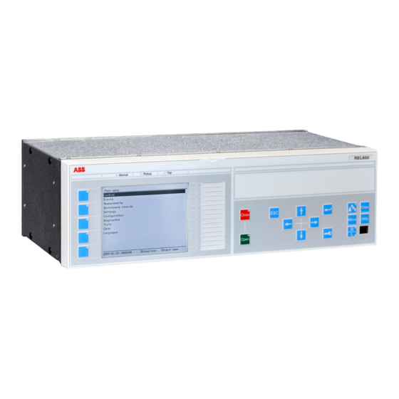
Section 5 1MRK 506 334-UUS A Local human-machine interface Section 5 Local human-machine interface Local HMI ANSI12000175 V1 EN Figure 44: Local human-machine interface The LHMI of the IED contains the following elements: • Display (LCD) • Buttons • LED indicators •... - Page 112 Section 5 1MRK 506 334-UUS A Local human-machine interface IEC13000063-1-en.vsd IEC13000063 V1 EN Figure 45: Display layout 1 Path 2 Content 3 Status 4 Scroll bar (appears when needed) The function button panel shows on request what actions are possible with the function buttons.
-
Page 113: Leds
Section 5 1MRK 506 334-UUS A Local human-machine interface ANSI12000025-1-en.vsd ANSI12000025 V1 EN Figure 46: Function button panel The alarm LED panel shows on request the alarm text labels for the alarm LEDs. Three alarm LED pages are available. GUID-D20BB1F1-FDF7-49AD-9980-F91A38B2107D V1 EN Figure 47: Alarm LED panel The function button and alarm LED panels are not visible at the same time. -
Page 114: Keypad
Section 5 1MRK 506 334-UUS A Local human-machine interface There are 3 separate pages of LEDs available. The 15 physical three-color LEDs in one LED group can indicate 45 different signals. Altogether, 135 signals can be indicated since there are three LED groups. The LEDs can be configured with PCM600 and the operation mode can be selected with the LHMI or PCM600. - Page 115 Section 5 1MRK 506 334-UUS A Local human-machine interface ANSI11000247 V2 EN Figure 48: LHMI keypad with object control, navigation and command push buttons and RJ-45 communication port 1...5 Function button Close Open Escape Left Down Right User Log on Enter Remote/Local Uplink LED...
-
Page 116: Local Hmi Functionality
Section 5 1MRK 506 334-UUS A Local human-machine interface 5.1.4 Local HMI functionality 5.1.4.1 Protection and alarm indication Protection indicators The protection indicator LEDs are Normal, Pickup and Trip. Table 3: Normal LED (green) LED state Description Auxiliary supply voltage is disconnected. Normal operation. -
Page 117: Parameter Management
Section 5 1MRK 506 334-UUS A Local human-machine interface Table 6: Alarm indications LED state Description Normal operation. All activation signals are off. • Follow-S sequence: The activation signal is on. • LatchedColl-S sequence: The activation signal is on, or it is off but the indication has not been acknowledged. - Page 118 Section 5 1MRK 506 334-UUS A Local human-machine interface GUID-D71BA06D-3769-4ACB-8A32-5D02EA473326 V1 EN Figure 49: RJ-45 communication port and green indicator LED 1 RJ-45 connector 2 Green indicator LED When a computer is connected to the IED front port with a crossed-over cable, the IED's DHCP server for the front interface assigns an IP address to the computer if DHCPServer = Enabled.
-
Page 119: Five Zone Distance Protection, Quadrilateral And Mho Characteristic Zqmpdis (21)
Section 6 1MRK 506 334-UUS A Impedance protection Section 6 Impedance protection Five zone distance protection, quadrilateral and mho characteristic ZQMPDIS (21) 6.1.1 Identification Function description IEC 61850 IEC 60617 ANSI/IEEE C37.2 identification identification device number Five zone distance protection, ZQMPDIS quadrilateral and mho characteristic S00346 V1 EN... -
Page 120: System Grounding
Section 6 1MRK 506 334-UUS A Impedance protection selecting the different characteristics for different loops of a zone makes ZQMPDIS (21) highly effective distance protection function. 6.1.2.1 System grounding The type of system grounding plays an important role when designing the protection system. - Page 121 Section 6 1MRK 506 334-UUS A Impedance protection The voltage on the healthy phases is generally lower than 140% of the nominal phase-to- ground voltage. This corresponds to about 80% of the nominal phase-to-phase voltage. The high zero-sequence current in solidly grounded networks makes it possible to use impedance measuring techniques to detect ground faults.
- Page 122 Section 6 1MRK 506 334-UUS A Impedance protection The magnitude of the ground-fault current in effectively grounded networks is high enough for impedance measuring elements to detect ground faults. However, in the same way as for solidlygrounded networks, distance protection has limited possibilities to detect high resistance faults and should therefore always be complemented with other protection function(s) that can carry out the fault clearance in this case.
-
Page 123: Fault Infeed From Remote End
Section 6 1MRK 506 334-UUS A Impedance protection en05000216_ansi.vsd ANSI05000216 V1 EN Figure 51: High impedance grounded network The operation of high impedance grounded networks is different compared to solid grounded networks where all major faults have to be cleared very fast. In high impedance grounded networks, some system operators do not clear single phase-to-ground faults immediately;... -
Page 124: Short Line Application
Section 6 1MRK 506 334-UUS A Impedance protection × × (Equation 42) EQUATION1274 V2 EN The infeed factor (I can be very high, 10-20 depending on the differences in source impedances at local and remote end. p*ZL (1-p)*ZL en05000217_ansi.vsd ANSI05000217 V1 EN Figure 52: Influence of fault current infeed from remote line end The effect of fault current infeed from remote line end is one of the most driving factors... -
Page 125: Long Transmission Line Application
Section 6 1MRK 506 334-UUS A Impedance protection Table 7: Definition of short and very short line Line category 110 kV 500 kV Very short line 0.75–3.6 miles 3–15 miles Short line 4–7 miles 15–30 miles For very short line applications the underreaching zone 1 cannot be used as the voltage drop distribution through out the line will be too low causing risk for overreaching. -
Page 126: Parallel Line Application With Mutual Coupling
Section 6 1MRK 506 334-UUS A Impedance protection 6.1.2.5 Parallel line application with mutual coupling General Introduction of parallel lines in the network is increasing due to difficulties to get necessary area for new lines. Parallel lines introduce an error in the measurement due to the mutual coupling between the parallel lines. - Page 127 Section 6 1MRK 506 334-UUS A Impedance protection Most multi circuit lines have two parallel operating circuits. Parallel line applications In this type of networks, the parallel transmission lines terminate at common nodes at both ends. We consider the three most common operation modes: parallel line in service.
- Page 128 Section 6 1MRK 506 334-UUS A Impedance protection Maximum overreach will occur if the fault current infeed from remote line end is weak. If considering a single phase-to-ground fault at 'p' unit of the line length from A to B on the parallel line for the case when the fault current infeed from remote line end is zero, the voltage V in the faulty phase at A side as in equation 43.
- Page 129 Section 6 1MRK 506 334-UUS A Impedance protection OPEN OPEN CLOSED CLOSED en05000222_ansi.vsd ANSI05000222 V1 EN Figure 56: The parallel line is out of service and grounded When the parallel line is out of service and grounded at both line ends on the bus bar side of the line CTs so that zero sequence current can flow on the parallel line, the equivalent zero sequence circuit of the parallel lines will be according to figure 57.
- Page 130 Section 6 1MRK 506 334-UUS A Impedance protection Parallel line out of service and not grounded OPEN OPEN CLOSED CLOSED en05000223_ansi.vsd ANSI05000223 V1 EN Figure 58: Parallel line is out of service and not grounded When the parallel line is out of service and not grounded, the zero sequence on that line can only flow through the line admittance to the ground.
-
Page 131: Tapped Line Application
Section 6 1MRK 506 334-UUS A Impedance protection Ensure that the underreaching zones from both line ends will overlap a sufficient amount (at least 10%) in the middle of the protected circuit. 6.1.2.6 Tapped line application en05000224_ansi.vsd ANSI05000224 V1 EN Figure 60: Example of tapped line with Auto transformer This application gives rise to similar problem that was highlighted in section... - Page 132 Section 6 1MRK 506 334-UUS A Impedance protection Where: and Z is the line impedance from the A respective C station to the T point. and I is fault current from A respective C station for fault between T and B. V2/V1 Transformation ratio for transformation of impedance at V1 side of the transformer to the measuring side V2 (it is assumed that current and voltage distance function is taken...
-
Page 133: Load Encroachment
Section 6 1MRK 506 334-UUS A Impedance protection × 28707 L Rarc (Equation 48) EQUATION1456 V1 EN where: represents the length of the arc (in meters). This equation applies for the distance protection zone 1. Consider approximately three times arc foot spacing for the zone 2 and wind speed of approximately 30 m/h is the actual fault current in A. - Page 134 Section 6 1MRK 506 334-UUS A Impedance protection Load impedance area in LdAngle forward direction LdAngle LdAngle LdAngle RLdFwd RldRev ANSI05000495_2_en.vsd ANSI05000495 V2 EN Figure 61: Load encroachment phenomena and shaped load encroachment characteristic defined in Phase selection with load encroachment function FDPSPDIS (21) Load Load...
-
Page 135: Setting Guidelines
Section 6 1MRK 506 334-UUS A Impedance protection to load encroachment. The part of the load encroachment sector that comes inside the mho circle will not cause a trip if FMPSPDIS (21) is activated for the zone measurement. This is valid in both directions. LdAngle LdAngle LdAngle... -
Page 136: Setting Of Characteristic
Section 6 1MRK 506 334-UUS A Impedance protection The following basics should be considered, depending on application, when doing the setting calculations: • Errors introduced by current and voltage instrument transformers, particularly under transient conditions. • Inaccuracies in the line zero-sequence impedance data, and their effect on the calculated value of the ground-return compensation factor. - Page 137 Section 6 1MRK 506 334-UUS A Impedance protection CharPPZx CharPGZx where x=1- 5 CharPPZx Mho characteristic CharPGZx where x=1- 5 Quadrilateral characteristic CharPPZx CharPGZx where x=1- 5 Mho and Quadrilateral characteristic ANSI11000265_1_en.vsd ANSI11000265 V1 EN Figure 64: Impedance characteristic Complex characteristic can be formed with the ZQMPDIS ( 21) function. Figure shows for example, when zone 1 is set to combined quadrilateral and mho characteristic, zone 2 is set to forward mho characteristic, zone 3 is set to reverse mho characteristic and, zone...
- Page 138 Section 6 1MRK 506 334-UUS A Impedance protection IEC11000278_1_en.vsd IEC11000278 V1 EN Figure 65: Combined impedance characteristic Setting of zone 1 The different errors mentioned earlier usually require a limitation of the underreaching zone (normally zone 1) to 75 - 90% of the protected line. In case of parallel lines, consider the influence of the mutual coupling according to section "Parallel line application with mutual coupling"...
- Page 139 Section 6 1MRK 506 334-UUS A Impedance protection The setting shall generally not exceed 80% of the following impedances: • The impedance corresponding to the protected line, plus the first zone reach of the shortest adjacent line. • The impedance corresponding to the protected line, plus the impedance of the maximum number of transformers operating in parallel on the bus at the remote end of the protected line.
- Page 140 Section 6 1MRK 506 334-UUS A Impedance protection Consider the possible enlarging factor that might exist due to fault infeed from adjacent lines. Equation can be used to calculate the reach in reverse direction when the zone is used for blocking scheme, weak-end infeed, and so on. ³...
- Page 141 Section 6 1MRK 506 334-UUS A Impedance protection Setting of minimum operate currents The operation of the distance function will be blocked if the magnitude of the currents is below the set value of the parameter IMinOpPP and IMinOpPG. The default setting of IMinOpPP and IMinOpPG is 15% of IBase. The values have been proven in practice to be suitable in most of the applications.
-
Page 142: Quadrilateral Characteristics
Section 6 1MRK 506 334-UUS A Impedance protection 6.1.3.3 Quadrilateral characteristics Load impedance limitation, without load encroachment function The following instructions are valid when Phase selection with load encroachment, quadrilateral characteristic function FDPSPDIS (21) is not activated. To deactivate the function, the setting of the load resistance RLdFwd and RldRev in FDPSPDIS (21) must be set to max value (3000). - Page 143 Section 6 1MRK 506 334-UUS A Impedance protection This equation is applicable only when the loop characteristic angle for the single phase-to- ground faults is more than three times as large as the maximum expected load-impedance angle. For the case when the loop characteristic angle is less than three times the load- impedance angle, more accurate calculations are necessary according to equation 54.
-
Page 144: Mho Characteristics
Section 6 1MRK 506 334-UUS A Impedance protection 6.1.3.4 Mho characteristics Load impedance limitation, with load encroachment function activated The parameters for load encroachment shaping of the characteristic are found in the description of Faulty phase identification with load encroachment for mho (FMPSPDIS). Load impedance limitation, without load encroachment function The following instruction is valid when the load encroachment function or blinder function is not activated (BlinderMode=Disabled). -
Page 145: Phase Selection With Load Enchroachment, Quadrilateral Characteristic Fdpspdis (21)
Section 6 1MRK 506 334-UUS A Impedance protection Phase selection with load enchroachment, quadrilateral characteristic FDPSPDIS (21) 6.2.1 Identification Function description IEC 61850 IEC 60617 ANSI/IEEE C37.2 identification identification device number Phase selection with load FDPSPDIS encroachment, quadrilateral characteristic Z<phs SYMBOL-DD V1 EN 6.2.2 Application... - Page 146 Section 6 1MRK 506 334-UUS A Impedance protection STCNDZI or DLECND must be connected to input STCNDZI on ZMQPDIS (21), distance measuring block. For normal overhead lines, the angle for the loop impedance φ for phase-to-ground fault is defined according to equation 59. arctan (Equation 59) EQUATION2115 V1 EN...
- Page 147 Section 6 1MRK 506 334-UUS A Impedance protection ( / loop) 60° 60° ( / loop) IEC09000043_1_en.vsd IEC09000043 V1 EN Figure 67: Relation between distance protection ZQMPDIS (21) and FDPSPDIS (21) for phase-to-ground fault φloop>60° (setting parameters in italic) 1 FDPSPDIS (21) (red line) 2 ZQMPDIS(21) RFltRevPG +XN)/tan(60°)
- Page 148 Section 6 1MRK 506 334-UUS A Impedance protection Reactive reach The reactive reach in forward direction must as minimum be set to cover the measuring zone used in the Teleprotection schemes, mostly zone 2. Equation and equation gives the minimum recommended reactive reach. ³...
- Page 149 Section 6 1MRK 506 334-UUS A Impedance protection Resistive reach The resistive reach in reverse direction must be set longer than the longest reverse zones. In blocking schemes it must be set longer than the overreaching zone at remote end that is used in the communication scheme.
- Page 150 Section 6 1MRK 506 334-UUS A Impedance protection ( / phase) 60° 60° ( / phase) IEC09000257_1_en.vsd IEC09000257 V1 EN Figure 68: Relation between distance protection (ZQMPDIS) (21) and FDPSPDIS (21) characteristic for phase-to-phase fault for φline>60° (setting parameters in italic) 1 FDPSPDIS (21)(red line) 2 ZQMPDIS(21) 3 0.5 ·...
-
Page 151: Resistive Reach With Load Encroachment Characteristic
Section 6 1MRK 506 334-UUS A Impedance protection 6.2.3.2 Resistive reach with load encroachment characteristic The procedure for calculating the settings for the load encroachment consist basically to define the load angle LdAngle, the blinder RLdFwd in forward direction and blinder RLdRev in reverse direction, as shown in figure 69. -
Page 152: Minimum Operate Currents
Section 6 1MRK 506 334-UUS A Impedance protection The resistive boundary RLdRev for load encroachment characteristic in reverse direction can be calculated in the same way as RLdFwd, but use maximum importing power that might occur instead of maximum exporting power and the relevant Vmin voltage for this condition. -
Page 153: Setting Guidelines
Section 6 1MRK 506 334-UUS A Impedance protection zone distance protection, mho characteristic (ZQMPDIS, 21) without interfering with the load. The load encroachment algorithm and the blinder functions are always activated in the phase selector. The influence from these functions on the zone measurement characteristic has to be activated by switching the setting parameter LoadEnchMode in ZQMPDIS (21) for the respective measuring zone(s) to Enabled. -
Page 154: Load Encroachment
Section 6 1MRK 506 334-UUS A Impedance protection ILoad × VLmn (Equation 67) EQUATION1615-ANSI V1 EN where: Smax is the maximal apparent power transfer during emergency conditions and VLmn is the phase-to-phase voltage during the emergency conditions at the IED location. 6.3.3.1 Load encroachment The load encroachment function has two setting parameters, RLd for the load resistance... -
Page 155: Additional Distance Protection Directional Function For Ground Faults Zdardir (21D)
Section 6 1MRK 506 334-UUS A Impedance protection Zload (Equation 69) EQUATION1753-ANSI V1 EN Where: is the minimum phase-to-phase voltage in kV is the maximum apparent power in MVA. The load angle LdAngle can be derived according to equation 70: æ... -
Page 156: Functionalityapplication
Section 6 1MRK 506 334-UUS A Impedance protection 6.4.2 FunctionalityApplication The evaluation of the direction to the fault is made in the directional element ZDNRDIR (21D) for the quadrilateral and mho characteristic distance protections ZQMPDIS (21). 6.4.3 Setting guidelines AngleRCA and AngleOp: these settings define the operation characteristic. Setting AngleRCA is used to turn the directional characteristic, if the expected fault current angle does not coincide with the polarizing quantity to produce the maximum torque. - Page 157 Section 6 1MRK 506 334-UUS A Impedance protection • on solidly grounded systems V2 may be larger than V . If the bus behind the IED location is a strong zero-sequence source, the negative sequence voltage available at the IED location is higher than the zero-sequence voltage. •...
-
Page 158: Phase Preference Logic Pplphiz
Section 6 1MRK 506 334-UUS A Impedance protection + × × AngleRCA k I e (Equation 72) EQUATION1638-ANSI V2 EN The negative-sequence voltage polarization with negative-sequence current compensation (-U2Comp) compares correspondingly I with (see equation 73), and similarly it must be ensured that |V | >>... - Page 159 Section 6 1MRK 506 334-UUS A Impedance protection the fault. When cross-country faults occur, the practice is to trip only one of the faulty lines. In other cases, a sensitive, directional ground-fault protection is provided to trip, but due to the low fault currents long tripping times are utilized. Figure shows an occurring cross-country fault.
- Page 160 Section 6 1MRK 506 334-UUS A Impedance protection en06000551_ansi.vsd ANSI06000551 V1 EN Figure 72: The voltage increase on healthy phases and occurring neutral point voltage (3V0) at a single phase-to-ground fault and an occurring cross- country fault on different feeders in a sub-transmission network, high impedance (resistance, reactance) grounded PPLPHIZ is connected between Five zone distance protection, quadrilateral characteristic function (ZQMPDIS, 21) and Phase selection with load encroachment, quadrilateral...
- Page 161 Section 6 1MRK 506 334-UUS A Impedance protection FDPSPDIS (21) ZQDPDIS (21) I3P* TRIP I3P* TRIP V3P* PICKUP V3P* TRZ1 BLOCK TRZ2 BLOCK FWD_A DIRCND FWD_B BLKZ TRZ3 FWD_C BLKTR TRZ4 FWD_G PHSEL TRZ5 REV_A DIRCND PICKUP BLKPG PU_Z1 REV_B REV_C BLKPP PU_Z2...
-
Page 162: Setting Guidelines
Section 6 1MRK 506 334-UUS A Impedance protection The function has a block input (BLOCK) to block start from the function if required in certain conditions. 6.5.3 Setting guidelines The parameters for the Phase preference logic function PPLPHIZ are set via the local HMI or PCM600. -
Page 163: Power Swing Detection Zmrpsb (68)
Section 6 1MRK 506 334-UUS A Impedance protection where the IN is the fault current level in the faulty phase. A high sensitivity need not to be achieved as the two-phase fault level normally is well above base current. tIN: The time delay for detecting that the fault is cross-country. Normal time setting is 0.1 - 0.15 s. -
Page 164: Basic Characteristics
Section 6 1MRK 506 334-UUS A Impedance protection Distance IEDs located in interconnected networks see these power swings as the swinging of the measured impedance in relay points. The measured impedance varies with time along a locus in an impedance plane, see figure 75. This locus can enter the operating characteristic of a distance protection and cause, if no preventive measures have been considered, its unwanted operation. - Page 165 Section 6 1MRK 506 334-UUS A Impedance protection GlobalBaseSel: Selects the global base value group used by the function to define (IBase), (VBase) and (SBase). = const = f(t) 99001019_ansi.vsd ANSI99001019 V1 EN Figure 76: Protected power line as part of a two-machine system Reduce the power system with protected power line into equivalent two-machine system with positive sequence source impedances Z behind the IED and Z...
- Page 166 Section 6 1MRK 506 334-UUS A Impedance protection Rated secondary current of current protection transformers used EQUATION1734 V1 EN Line positive sequence impedance 10.71 75.6 EQUATION1328 V1 EN Positive sequence source impedance behind A bus 1.15 43.5 EQUATION1329 V1 EN Positive sequence source impedance behind B bus 35.7 EQUATION1330 V1 EN...
- Page 167 Section 6 1MRK 506 334-UUS A Impedance protection 144.4 1000 (Equation 75) EQUATION1736-ANSI V1 EN The minimum load resistance R at maximum load and minimum system voltage is Lmin equal to equation 76. × × 144.4 0.95 137.2 (Equation 76) EQUATION1338 V1 EN The system impedance Z is determined as a sum of all impedance in an equivalent two-...
- Page 168 Section 6 1MRK 506 334-UUS A Impedance protection ANSI05000283 V1 EN Figure 77: Impedance diagrams with corresponding impedances under consideration The outer boundary of oscillation detection characteristic in forward direction RLdOutFw should be set with certain safety margin K compared to the minimum expected load resistance R .
- Page 169 Section 6 1MRK 506 334-UUS A Impedance protection • = 0.9 for lines longer than 100 miles • = 0.85 for lines between 50 and 100 miles • = 0.8 for lines shorter than 50 miles Multiply the required resistance for the same safety factor K with the ratio between actual voltage and 400kV when the rated voltage of the line under consideration is higher than 400kV.
- Page 170 Section 6 1MRK 506 334-UUS A Impedance protection ° - ° 76.5 64.5 13.3 × ° × ° 2.5 360 (Equation 85) EQUATION1347 V1 EN The general tendency should be to set the tP1 time to at least 30 ms, if possible. Since it is not possible to further increase the external load angle δ...
- Page 171 Section 6 1MRK 506 334-UUS A Impedance protection tP2 = 10 ms Consider RLdInFw = 75.0Ω. Do not forget to adjust the setting of load encroachment resistance RLdFwd in Phase selection with load encroachment (FDPSPDIS, 21) to the value equal to or less than the calculated value RLdInFw. It is at the same time necessary to adjust the load angle in FDPSPDIS (21) to follow the condition presented in equation 91.
-
Page 172: Automatic Switch Onto Fault Logic, Voltage And Current Based Zcvpsof
Section 6 1MRK 506 334-UUS A Impedance protection (ZMRPSB, 68) during the power swing, even after the transient impedance leaves ZMRPSB (68) operating characteristic and is expected to return within a certain time due to continuous swinging. Consider the minimum possible speed of power swinging in a particular system. -
Page 173: Setting Guidelines
Section 6 1MRK 506 334-UUS A Impedance protection Other protection functions like time delayed phase and zero sequence overcurrent function can be connected to ZCVPSOF function to increase the dependability in the scheme. 6.7.3 Setting guidelines The parameters for Automatic switch onto fault logic, voltage and current based function (ZCVPSOF) are set via the local HMI or Protection and Control Manager PCM600. - Page 174 Section 6 1MRK 506 334-UUS A Impedance protection time to consider the voltage recovery time at energizing the line. A setting equal to 0.1 sec have been proven to be suitable in most cases from field experience. AutoInit: Automatic activating of the ZCVPSOF function is by default set to Disabled. If automatic activation Deadline detection is required, set the parameter Autoinit to Enabled.
-
Page 175: Phpioc (50)
Section 7 1MRK 506 334-UUS A Current protection Section 7 Current protection Instantaneous phase overcurrent protection 3-phase output PHPIOC (50) 7.1.1 Identification Function description IEC 61850 IEC 60617 ANSI/IEEE C37.2 identification identification device number Instantaneous phase overcurrent PHPIOC protection 3-phase output 3I>>... -
Page 176: Setting Guidelines
Section 7 1MRK 506 334-UUS A Current protection operate very quickly for faults very close to the generation (and relay) point, for which very high fault currents are characteristic. The instantaneous phase overcurrent protection 3-phase output PHPIOC (50) can operate in 10 ms for faults characterized by very high currents. - Page 177 Section 7 1MRK 506 334-UUS A Current protection Fault ANSI09000022-1-en.vsd ANSI09000022 V1 EN Figure 78: Through fault current from A to B: I Then a fault in A has to be applied and the through fault current I has to be calculated, figure 79.
-
Page 178: Meshed Network With Parallel Line
Section 7 1MRK 506 334-UUS A Current protection The minimum primary setting (Is) for the instantaneous phase overcurrent protection 3- phase output is then: ³ × (Equation 95) EQUATION79 V3 EN The protection function can be used for the specific application only if this setting value is equal to or less than the maximum fault current that the IED has to clear, I in figure 80. - Page 179 Section 7 1MRK 506 334-UUS A Current protection A fault in C has to be applied, and then the maximum current seen from the IED (I ) on the healthy line (this applies for single-phase-to-ground and two-phase-to-ground faults) is calculated. Line 1 Fault Line 2...
-
Page 180: Instantaneous Phase Overcurrent Protection Phase Segregated Output Sptpioc (50)
Section 7 1MRK 506 334-UUS A Current protection Instantaneous phase overcurrent protection phase segregated output SPTPIOC (50) 7.2.1 Identification Function description IEC 61850 IEC 60617 ANSI/IEEE C37.2 identification identification device number Instantaneous phase overcurrent SPTPIOC protection, phase segregated output 3I>> SYMBOL-Z V1 EN 7.2.2 Application... -
Page 181: Meshed Network Without Parallel Line
Section 7 1MRK 506 334-UUS A Current protection This protection function must operate only in a selective way. So check all system and transient conditions that could cause its unwanted operation. Detailed network studies can determine the operating conditions under which the highest possible fault current is expected on the line . - Page 182 Section 7 1MRK 506 334-UUS A Current protection Then a fault in A has to be applied and the through fault current I has to be calculated, figure 83. In order to get the maximum through fault current, the minimum value for Z and the maximum value for Z have to be considered.
-
Page 183: Meshed Network With Parallel Line
Section 7 1MRK 506 334-UUS A Current protection Fault ANSI10000275-1-en.vsd ANSI10000275 V1 EN Figure 84: Fault current: I The IED setting valuePickup is given in percentage of the primary base current value, IBase. The value for Pickup is given from this formula: ×... - Page 184 Section 7 1MRK 506 334-UUS A Current protection Line 1 Fault Line 2 ANSI10000278_2_en.vsd ANSI10000278 V2 EN Figure 85: Two parallel lines Influence form parallel line to the through fault current: The minimum theoretical current (I ) for the overcurrent protection function will be: ³...
-
Page 185: Identification
Section 7 1MRK 506 334-UUS A Current protection Four step phase overcurrent protection 3-phase output OC4PTOC (51/67) 7.3.1 Identification Function description IEC 61850 IEC 60617 ANSI/IEEE C37.2 identification identification device number Four step phase overcurrent protection OC4PTOC 51/67 3I> 3-phase output TOC-REVA V1 EN 7.3.2 Application... -
Page 186: Setting Guidelines
Section 7 1MRK 506 334-UUS A Current protection characteristics. The selectivity between different overcurrent protections is normally enabled by co-ordination between the function time delays of the different protections. To enable optimal co-ordination between all overcurrent protections, they should have the same time delay characteristic. -
Page 187: Settings For Steps 1 To 4
Section 7 1MRK 506 334-UUS A Current protection ANSI09000636-1-en.vsd ANSI09000636 V1 EN Figure 86: Directional function characteristic 1. RCA = Relay characteristic angle 55° 2. ROA = Relay operating angle 80° 3. Reverse 4. Forward 7.3.3.1 Settings for steps 1 to 4 n means step 1 and 4. - Page 188 Section 7 1MRK 506 334-UUS A Current protection Characteristn: Selection of time characteristic for step n. Definite time delay and different types of inverse time characteristics are available according to table 9. Step 2 and 3 are always definite time delayed. Table 9: Inverse time characteristics Curve name...
-
Page 189: Nd Harmonic Restrain
Section 7 1MRK 506 334-UUS A Current protection parameter the operation time of the step can never be shorter than the setting. Setting range: 0.000 - 60.000s in steps of 0.001s. Operate time tnMin IMinn Current IEC09000164-2 IEC09000164 V2 EN Figure 87: Minimum operate current and operation time for inverse time characteristics... - Page 190 Section 7 1MRK 506 334-UUS A Current protection 2ndHarmStab: The rate of 2nd harmonic current content for activation of the 2nd harmonic restrain signal, to block chosen steps. The setting is given in % of the fundamental frequency residual current. The setting range is 5 - 100% in steps of 1%. The default setting is 20% and can be used if a deeper investigation shows that no other value is needed..
- Page 191 Section 7 1MRK 506 334-UUS A Current protection Im ax ³ × Ipu 1.2 (Equation 106) EQUATION1262 V2 EN where: is a safety factor is the resetting ratio of the protection Imax is the maximum load current The maximum load current on the line has to be estimated. There is also a demand that all faults, within the zone that the protection shall cover, must be detected by the phase overcurrent protection.
- Page 192 Section 7 1MRK 506 334-UUS A Current protection ³ × × high (Equation 109) EQUATION1265 V1 EN where: is a safety factor is a factor that takes care of the transient overreach due to the DC component of the fault current and can be considered to be less than 1.1 Iscmax is the largest fault current at a fault at the most remote point of the primary protection zone.
- Page 193 Section 7 1MRK 506 334-UUS A Current protection en05000204.wmf IEC05000204 V1 EN Figure 89: Fault time with maintained selectivity To assure selectivity between different protections, in the radial network, there have to be a minimum time difference Dt between the time delays of two protections. The minimum time difference can be determined for different cases.
- Page 194 Section 7 1MRK 506 334-UUS A Current protection have instantaneous function. The overcurrent protection of IED A1 must have a delayed function. The sequence of events during the fault can be described using a time axis, see figure 90. Feeder Time axis The fault Protection...
-
Page 195: Four Step Phase Overcurrent Protection Phase Segregated Output Oc4Sptoc 51_67
Section 7 1MRK 506 334-UUS A Current protection D ³ (Equation 110) EQUATION1266 V1 EN where it is considered that: the operate time of overcurrent protection B1 is 40 ms the breaker open time is 100 ms the resetting time of protection A1 is 40 ms and the additional margin is 40 ms... -
Page 196: Setting Guidelines
Section 7 1MRK 506 334-UUS A Current protection If VT inputs are not available or not connected, setting parameter DirModeSelx (x=step 1, 2, 3 or 4) shall be left to default value, Nondirectional, or set to Disabled. In many applications several steps with different current pick up levels and time delays are needed. - Page 197 Section 7 1MRK 506 334-UUS A Current protection The parameters for four step phase overcurrent protection phase segregated output OC4SPTOC (51_67) are set via the local HMI or Protection and Control IED Manager (PCM600). The following settings can be made for the four step phase overcurrent protection phase segregated output.
-
Page 198: Settings For Steps 1 To 4
Section 7 1MRK 506 334-UUS A Current protection ANSI09000636-1-en.vsd ANSI09000636 V1 EN Figure 91: Directional function characteristic 1. RCA = Relay characteristic angle 55° 2. ROA = Relay operating angle 80° 3. Reverse 4. Forward 7.4.3.1 Settings for steps 1 to 4 n: means step 1 and 4. - Page 199 Section 7 1MRK 506 334-UUS A Current protection DirModeSelx: The directional mode of step x. Possible settings are Disabled/Non- directional/ Forward/Reverse. Characteristn: Selection of time characteristic for step n. Definite time delay and different types of inverse time characteristics are available according to Table 10 .
-
Page 200: Nd Harmonic Restrain
Section 7 1MRK 506 334-UUS A Current protection tnMin: Minimum operate time for all inverse time characteristics. At high currents the inverse time characteristic might give a very short operation time. By setting this parameter the operation time of the step can never be shorter than the setting. Operate time tnMin IMinn... - Page 201 Section 7 1MRK 506 334-UUS A Current protection The pickup current setting inverse time protection or the lowest current step constant inverse time protection must be given a current setting so that the highest possible load current does not cause protection operation. Here consideration also has to be taken to the protection reset current, so that a short peak of overcurrent does not cause operation of the protection even when the overcurrent has ceased.
- Page 202 Section 7 1MRK 506 334-UUS A Current protection overcurrent protection. The minimum fault current Iscmin, to be detected by the protection, must be calculated. Taking this value as a base, the highest pick up current setting can be written according to equation 107. £...
-
Page 203: Example
Section 7 1MRK 506 334-UUS A Current protection IEC10000273-1-en.vsd IEC10000273 V1 EN Figure 94: Fault time with maintained selectivity To assure selectivity between different protections, in the radial network, there have to be a minimum time difference ∆t between the time delays of two protections. The minimum time difference can be determined for different cases. - Page 204 Section 7 1MRK 506 334-UUS A Current protection have instantaneous function. The overcurrent protection of IED A1 must have a delayed function. The sequence of events during the fault can be described using a time axis, see figure 95. Feeder Time axis The fault Protection...
-
Page 205: Instantaneous Residual Overcurrent Protection Efpioc (50N)
Section 7 1MRK 506 334-UUS A Current protection • the operate time of overcurrent protection B1 is 40 ms • the breaker open time is 100 ms • the resetting time of protection A1 is 40 ms • the additional margin is 40 ms Instantaneous residual overcurrent protection EFPIOC (50N) 7.5.1... - Page 206 Section 7 1MRK 506 334-UUS A Current protection The basic requirement is to assure selectivity, that is EFPIOC (50N) shall not be allowed to operate for faults at other objects than the protected object (line). For a normal line in a meshed system single phase-to-ground faults and phase-to-phase- to-ground faults shall be calculated as shown in figure and figure 97.
- Page 207 Section 7 1MRK 506 334-UUS A Current protection ³ Imin MAX I (Equation 116) EQUATION284 V1 EN A safety margin of 5% for the maximum static inaccuracy and a safety margin of 5% for maximum possible transient overreach have to be introduced. An additional 20% is suggested due to inaccuracy of instrument transformers under transient conditions and inaccuracy in the system data.
-
Page 208: Four Step Residual Overcurrent Protection, Zero, Negative Sequence Direction Ef4Ptoc (51N/67N)
Section 7 1MRK 506 334-UUS A Current protection I ³ 1.3.I (Equation 119) EQUATION288 V2 EN Transformer inrush current shall be considered. The setting of the protection is set as a percentage of the base current (IBase). Operation: set the protection to Enabled or Disabled. Pickup: Set operate current in % of IBase. - Page 209 Section 7 1MRK 506 334-UUS A Current protection • Ground-fault protection of different kinds of equipment connected to the power system such as shunt capacitor banks, shunt reactors and others. • Negative sequence direcitonal ground-fault protection of feeders with PTs connected in Open Delta connection from which it is not possible to derive Zero sequence voltage.
-
Page 210: Setting Guidelines
Section 7 1MRK 506 334-UUS A Current protection Curve name ANSI Long Time Extremely Inverse ANSI Long Time Very Inverse ANSI Long Time Inverse IEC Normal Inverse IEC Very Inverse IEC Inverse IEC Extremely Inverse IEC Short Time Inverse IEC Long Time Inverse IEC Definite Time ASEA RI RXIDG (logarithmic) -
Page 211: Settings For Steps 1 And 4
Section 7 1MRK 506 334-UUS A Current protection SeqTypeIPol: It is used to select type of current polarization quantity, i.e. ZeroSeq and NegSeq for direction detection. SeqTypeIDir: It is used to select type of operating quantity, i.e. ZeroSeq and NegSeq for direction detection. -
Page 212: Common Settings For All Steps
Section 7 1MRK 506 334-UUS A Current protection TDn: Time multiplier for inverse time delay for step n. IMinn: Minimum operate current for step n in % of IBase. Set IMinn below Pickupx for every step to achieve ANSI reset characteristic according to standard. If IMinn is set above Pickupx for any step then signal will reset at current equals to zero. - Page 213 Section 7 1MRK 506 334-UUS A Current protection V pol = 3V or V Operation IDirPU en 05000135-4- ansi. vsd ANSI05000135 V3 EN Figure 100: Relay characteristic angle given in degree In a normal transmission network a normal value of RCA is about 65°. The setting range is -180°...
-
Page 214: Nd Harmonic Restrain
Section 7 1MRK 506 334-UUS A Current protection protection. The maximum ground-fault current at the local source can be used to calculate the value of ZN as V/(√3 · 3I ) Typically, the minimum ZNPol (3 · zero sequence source) is set. - Page 215 Section 7 1MRK 506 334-UUS A Current protection The protection measures the residual current out on the protected line. The protection function has a directional function where the residual voltage (zero-sequence voltage) is the polarizing quantity. The residual voltage and current can be internally generated when a three-phase set of voltage transformers and current transformers are used.
- Page 216 Section 7 1MRK 506 334-UUS A Current protection One- or two-phase ground-fault ANSI05000150_2_en.vsd ANSI05000150 V2 EN Figure 102: Step 1, first calculation The residual current out on the line is calculated at a fault on the remote busbar (one- or two-phase-to-ground fault).
- Page 217 Section 7 1MRK 506 334-UUS A Current protection The requirement is now according to equation 121. ³ × 1.2 3I (remote busbar with one line out) step1 (Equation 121) EQUATION1200 V3 EN A higher value of step 1 might be necessary if a big power transformer (Y0/D) at remote bus bar is disconnected.
- Page 218 Section 7 1MRK 506 334-UUS A Current protection 50/51N One- or two-phase ground-fault ANSI05000154_2_en.vsd ANSI05000154 V2 EN Figure 105: Step 2, check of reach calculation The residual current, out on the line, is calculated at an operational case with minimal ground-fault current.
- Page 219 Section 7 1MRK 506 334-UUS A Current protection Step 3 This step has directional function and a time delay slightly larger than step 2, often 0.8 s. Step 3 shall enable selective trip of ground faults having higher fault resistance to ground, compared to step 2.
-
Page 220: Sensitive Directional Residual Overcurrent And Power Protection Sdepsde (67N)
Section 7 1MRK 506 334-UUS A Current protection Sensitive directional residual overcurrent and power protection SDEPSDE (67N) 7.7.1 Identification Function description IEC 61850 IEC 60617 ANSI/IEEE C37.2 identification identification device number Sensitive directional residual over SDEPSDE current and power protection 7.7.2 Application In networks with high impedance grounding, the phase-to-ground fault current is... - Page 221 Section 7 1MRK 506 334-UUS A Current protection As the magnitude of the residual current is independent of the fault location the selectivity of the ground-fault protection is achieved by time selectivity. When should the sensitive directional residual overcurrent protection be used and when should the sensitive directional residual power protection be used? Consider the following facts: •...
-
Page 222: Setting Guidelines
Section 7 1MRK 506 334-UUS A Current protection 7.7.3 Setting guidelines The sensitive ground-fault protection is intended to be used in high impedance grounded systems, or in systems with resistive grounding where the neutral point resistor gives an ground-fault current larger than what normal high impedance gives but smaller than the phase to phase short circuit current. - Page 223 Section 7 1MRK 506 334-UUS A Current protection Where is the capacitive ground-fault current at a non-resistive phase to ground-fault is the capacitive reactance to ground In a system with a neutral point resistor (resistance grounded system) the impedance Z can be calculated as: ×...
- Page 224 Section 7 1MRK 506 334-UUS A Current protection Source impedance (pos. seq) (pos. seq) (zero seq) Substation A (pos. seq) lineAB,1 (zero seq) lineAB,0 Substation B (pos. seq) lineBC,1 (zero seq) lineBC,0 Phase to ground fault en06000654_ansi.vsd ANSI06000654 V1 EN Figure 109: Equivalent of power system for calculation of setting The residual fault current can be written:...
- Page 225 Section 7 1MRK 506 334-UUS A Current protection × 3I (Z 3R ) T ,0 (Equation 132) EQUATION2024-ANSI V1 EN × 3I (Z T ,0 lineAB,0 (Equation 133) EQUATION2025-ANSI V1 EN The residual power, measured by the sensitive ground-fault protections in A and B will be: ×...
- Page 226 Section 7 1MRK 506 334-UUS A Current protection The function can be set Enabled/Disabled with the setting of Operation. With the setting OpModeSel the principle of directional function is chosen. With OpModeSel set to 3I0cosfi the current component in the direction equal to the characteristic angleRCADir has the maximum sensitivity.
- Page 227 Section 7 1MRK 506 334-UUS A Current protection RCA = -90°, ROA = 90° ) – ang(V = ang(3I en06000649_ansi.vsd ANSI06000649 V1 EN Figure 111: Characteristic for RCADir equal to -90° When OpModeSel is set to 3I03V0Cosfi the apparent residual power component in the direction is measured.
- Page 228 Section 7 1MRK 506 334-UUS A Current protection RCA = 0º ROA = 80º Operate area =-3V ANSI06000652-2-en.vsd ANSI06000652 V2 EN Figure 112: Characteristic for RCADir = 0° and ROADir = 80° DirMode is set Forward or Reverse to set the direction of the trip function from the directional residual current function.
- Page 229 Section 7 1MRK 506 334-UUS A Current protection INCosPhiPU is the operate current level for the directional function when OpModeSel is set 3I0Cosfi. The setting is given in % of IBase. The setting should be based on calculation of the active or capacitive ground-fault current at required sensitivity of the protection. SN_PU is the operate power level for the directional function when OpModeSel is set 3I03V0Cosfi.
-
Page 230: Time Delayed 2-Step Undercurrent Protection Uc2Ptuc (37)
Section 7 1MRK 506 334-UUS A Current protection IEC Normal Inverse IEC Very Inverse IEC Inverse IEC Extremely Inverse IEC Short Time Inverse IEC Long Time Inverse IEC Definite time ASEA RI RXIDG (logarithmic) The different characteristics are described in Technical Manual. tINNonDir is the definite time delay for the non directional ground-fault current protection, given in s. - Page 231 Section 7 1MRK 506 334-UUS A Current protection circuit breaker in another substation. Both examples involve a transfer trip scheme, to which a local low current criterion is added, to avoid unwanted trips, caused by false transfer trip signals. Power transformer, directly connected to the feeding line The main purpose of UC2PTUC (37) is to provide a local criterion, which is added to a received transfer trip signal, in order to increase the security of the overall tripping functionality.
-
Page 232: Setting Guidelines
Section 7 1MRK 506 334-UUS A Current protection functionality. A typical application for UC2PTUC (37) function is a line connected shunt reactor, as shown in figure 114. TRIP source Line Source Load Line connected TRIP shunt reactor ANSI11000092_1_en.vsd ANSI11000092 V1 EN Figure 114: High voltage power line with solidly connected shunt reactor Shunt reactors are generally protected by differential protection, which operates the local... -
Page 233: Thermal Overload Protection, One Time Constant Fahrenheit/Celsius Lfpttr/Lcpttr (26)
Section 7 1MRK 506 334-UUS A Current protection I2Mode: number of phases involved for operation for step2. I2<: high-set level of the current. If the current decreases below this limit the function picks up and issue start signals PU_ST2 and RI. t2: time delay of I2<... -
Page 234: Setting Guidelines
Section 7 1MRK 506 334-UUS A Current protection • The sag of overhead lines can reach unacceptable value. • If the temperature of conductors, for example aluminium conductors, get too high the material will be destroyed. • In cables the insulation can be damaged as a consequence of the overtemperature. As a consequence of this phase to phase or phase to ground faults can occur In stressed situations in the power system it can be required to overload lines and cables for a limited time. -
Page 235: Identification
Section 7 1MRK 506 334-UUS A Current protection TripTemp: Temperature value for trip of the protected circuit. For cables, a maximum allowed conductor temperature is often stated to be 190°F (88°C). For overhead lines, the critical temperature for aluminium conductor is about 190-210°F (88-99°C). For a copper conductor a normal figure is 160°F (71°C). -
Page 236: Setting Guidelines
Section 7 1MRK 506 334-UUS A Current protection through the breaker is made by means of current measurement or as detection of remaining trip signal (unconditional). CCRBRF (50BF) can also give a re-trip. This means that a second trip signal is sent to the protected circuit breaker. - Page 237 Section 7 1MRK 506 334-UUS A Current protection Table 12: Dependencies between parameters RetripMode and FunctionMode RetripMode FunctionMode Description Retrip Off the re-trip function is not activated CB Pos Check Current a phase current must be larger than the operate level to allow re- trip Contact re-trip is done when breaker...
- Page 238 Section 7 1MRK 506 334-UUS A Current protection t1: Time delay of the re-trip. The setting can be given within the range 0 – 60s in steps of 0.001 s. Typical setting is 0 – 50ms. t2: Time delay of the back-up trip. The choice of this setting is made as short as possible at the same time as unwanted operation must be avoided.
-
Page 239: Breaker Failure Protection Phase Segregated Activation And Output Csprbrf (50Bf)
Section 7 1MRK 506 334-UUS A Current protection Protection operate time Normal t cbopen Retrip delay t1 after re-trip The fault cbopen occurs BFPreset Margin Minimum back-up trip delay t2 Critical fault clearance time for stability Time Trip and Pickup CCRBRF (50BF) ANSI05000479_3_en.vsd... -
Page 240: Setting Guidelines
Section 7 1MRK 506 334-UUS A Current protection One necessary component in the fault clearance system is the circuit breaker. It is from practical and economical reason not feasible to duplicate the circuit breaker for the protected component. Instead a breaker failure protection is used. The Breaker failure protection, phase segregated activation and output (CSPRBRF 50BF) issues a back-up trip command to adjacent circuit breakers in case of failure to trip of the “normal”... - Page 241 Section 7 1MRK 506 334-UUS A Current protection Table 13: Dependencies between parameters RetripMode and FunctionMode RetripMode FunctionMode Description Retrip Off The re-trip function is not activated CB Pos Chec k Current A phase current must be larger than the operate level to allow re- trip Contact Re-trip is done when circuit...
- Page 242 Section 7 1MRK 506 334-UUS A Current protection The current setting should be chosen in accordance to the setting of the sensitive ground fault protection. The setting can be given within the range 2 – 200 % of IBase. t1: Time delay of the re-trip. The setting can be given within the range 0 – 60 s in steps of 0.001 s.
-
Page 243: Stub Protection Stbptoc (50Stb)
Section 7 1MRK 506 334-UUS A Current protection Protection operate time Normal t cbopen Retrip delay t1 after re-trip The fault cbopen occurs BFPreset Margin Minimum back-up trip delay t2 Critical fault clearance time for stability Time Trip and Pickup CSPRBRF ANSI10000280-1-en.vsd ANSI10000280 V1 EN... -
Page 244: Setting Guidelines
Section 7 1MRK 506 334-UUS A Current protection Open Disconnector ANSI11000172_1_en.vsd ANSI11000172 V1 EN Figure 117: Typical connection for stub protection in breaker-and-a-half arrangement. 7.12.3 Setting guidelines The parameters for Stub protection STBPTOC (50STB) are set via the local HMI or PCM600. -
Page 245: Pole Discrepancy Protection Ccrpld (52Pd)
Section 7 1MRK 506 334-UUS A Current protection IPickup: Current level for the Stub protection, set in % of IBase. This parameter should be set so that all faults on the stub can be detected. The setting should thus be based on fault calculations. -
Page 246: Setting Guidelines
Section 7 1MRK 506 334-UUS A Current protection 7.13.3 Setting guidelines The parameters for the Pole discordance protection CCRPLD (52PD) are set via the local HMI or PCM600. The following settings can be done for the pole discrepancy protection. GlobalBaseSel: Selects the global base value group used by the function to define (IBase), (VBase) and (SBase). -
Page 247: Setting Guidelines
Section 7 1MRK 506 334-UUS A Current protection unsymmetrical check on the line where the IED connected will give alarm or trip at detecting broken conductors. 7.14.3 Setting guidelines GlobalBaseSel: Selects the global base value group used by the function to define (IBase), (VBase) and (SBase). - Page 248 Section 7 1MRK 506 334-UUS A Current protection Often, the motoring condition may imply that the turbine is in a very dangerous state. The task of the reverse power protection is to protect the turbine and not to protect the generator itself.
-
Page 249: Directional Overpower Protection Goppdop (32)
Section 7 1MRK 506 334-UUS A Current protection A hydro turbine that rotates in water with closed wicket gates will draw electric power from the rest of the power system. This power will be about 10% of the rated power. If there is only air in the hydro turbine, the power demand will fall to about 3%. -
Page 250: Identification
Section 7 1MRK 506 334-UUS A Current protection 7.15.2.1 Identification Function description IEC 61850 IEC 60617 ANSI/IEEE C37.2 identification identification device number Directional overpower protection GOPPDOP P > DOCUMENT172362-IMG158942 V2 EN 7.15.2.2 Setting guidelines GlobalBaseSel: Selects the global base value group used by the function to define (IBase), (VBase) and (SBase). - Page 251 Section 7 1MRK 506 334-UUS A Current protection Mode Set value Formula used for complex power calculation = × × (Equation 148) EQUATION2044 V1 EN = × × (Equation 149) EQUATION2045 V1 EN = × × (Equation 150) EQUATION2046 V1 EN The function has two stages that can be set independently.
- Page 252 Section 7 1MRK 506 334-UUS A Current protection Operate Power1(2) Angle1(2) en06000440.vsd IEC06000440 V1 EN Figure 119: Overpower mode The setting Power1(2) gives the power component pick up value in the Angle1(2) direction. The setting is given in p.u. of the generator rated power, see equation 151. Minimum recommended setting is 1.0% of S .
- Page 253 Section 7 1MRK 506 334-UUS A Current protection Angle1(2 ) = 180 Operate Power 1(2) IEC06000557-2-en.vsd IEC06000557 V2 EN Figure 120: For reverse power the set angle should be 180° in the overpower function TripDelay1(2) is set in seconds to give the time delay for trip of the stage after pick up. The possibility to have low pass filtering of the measured power can be made as shown in the formula: S TD S...
-
Page 254: Directional Underpower Protection Guppdup (37)
Section 7 1MRK 506 334-UUS A Current protection 7.15.3 Directional underpower protection GUPPDUP (37) 7.15.3.1 Identification Function description IEC 61850 IEC 60617 ANSI/IEEE C37.2 identification identification device number Directional underpower protection GUPPDUP P < SYMBOL-LL V2 EN 7.15.3.2 Setting guidelines GlobalBaseSel: Selects the global base value group used by the function to define (IBase), (VBase) and (SBase). - Page 255 Section 7 1MRK 506 334-UUS A Current protection Mode Set value Formula used for complex power calculation × (Equation 158) EQUATION2060-ANSI V1 EN = × × (Equation 159) EQUATION2061-ANSI V1 EN = × × (Equation 160) EQUATION2062-ANSI V1 EN = × ×...
- Page 256 Section 7 1MRK 506 334-UUS A Current protection Power1(2) Angle1(2) Operate en06000441.vsd IEC06000441 V1 EN Figure 121: Underpower mode The setting Power1(2) gives the power component pick up value in the Angle1(2) direction. The setting is given in p.u. of the generator rated power, see equation 162. Minimum recommended setting is 1.0% of S .
- Page 257 Section 7 1MRK 506 334-UUS A Current protection Operate ° Angle1(2) = 0 Power1(2) en06000556.vsd IEC06000556 V1 EN Figure 122: For low forward power the set angle should be 0° in the underpower function TripDelay1(2) is set in seconds to give the time delay for trip of the stage after pick up. The possibility to have low pass filtering of the measured power can be made as shown in the formula: S TD S...
-
Page 258: Negative Sequence Based Overcurrent Function Dnsptoc (46)
Section 7 1MRK 506 334-UUS A Current protection 7.16 Negative sequence based overcurrent function DNSPTOC (46) 7.16.1 Identification Function description IEC 61850 IEC 60617 ANSI/IEEE C37.2 identification identification device number Negative sequence based overcurrent DNSPTOC function 3I2> IEC09000132 V2 EN 7.16.2 Application Negative sequence based overcurrent function DNSPTOC (46) may be used in power line... - Page 259 Section 7 1MRK 506 334-UUS A Current protection • setting RCADir to value +65 degrees, that is, the negative sequence current typically lags the inverted negative sequence voltage for this angle during the fault • setting ROADir to value 90 degrees •...
-
Page 261: Two Step Undervoltage Protection Uv2Ptuv (27)
Section 8 1MRK 506 334-UUS A Voltage protection Section 8 Voltage protection Two step undervoltage protection UV2PTUV (27) 8.1.1 Identification Function description IEC 61850 IEC 60617 ANSI/IEEE C37.2 identification identification device number Two step undervoltage protection UV2PTUV 3U< SYMBOL-R-2U-GREATER-THAN V2 EN 8.1.2 Application Two-step undervoltage protection function (UV2PTUV ,27) is applicable in all situations,... -
Page 262: Setting Guidelines
Section 8 1MRK 506 334-UUS A Voltage protection Malfunctioning of a voltage regulator or wrong settings under manual control (symmetrical voltage decrease). Overload (symmetrical voltage decrease). Short circuits, often as phase-to-ground faults (unsymmetrical voltage decrease). UV2PTUV (27) prevents sensitive equipment from running under conditions that could cause their overheating and thus shorten their life time expectancy. -
Page 263: Voltage Instability Mitigation
Section 8 1MRK 506 334-UUS A Voltage protection 8.1.3.4 Voltage instability mitigation This setting is very much dependent on the power system characteristics, and thorough studies have to be made to find the suitable levels. 8.1.3.5 Backup protection for power system faults The setting must be below the lowest occurring "normal"... -
Page 264: Two Step Overvoltage Protection Ov2Ptov (59)
Section 8 1MRK 506 334-UUS A Voltage protection operation. If the function shall be insensitive for single phase-to-ground faults 2 out of 3 can be chosen. Pickupn: Set undervoltage operation value for step n (n=step 1 and 2), given as % of the global parameter VBase. -
Page 265: Application
Section 8 1MRK 506 334-UUS A Voltage protection 8.2.2 Application Two step overvoltage protection OV2PTOV (59) is applicable in all situations, where reliable detection of high voltage is necessary. OV2PTOV (59) is used for supervision and detection of abnormal conditions, which, in combination with other protection functions, increase the security of a complete protection system. - Page 266 Section 8 1MRK 506 334-UUS A Voltage protection There is a very wide application area where general overvoltage functions are used. All voltage related settings are made as a percentage of a settable base primary voltage, which normally is set to the nominal voltage level (phase-to-phase) of the power system or the high voltage equipment under consideration.
- Page 267 Section 8 1MRK 506 334-UUS A Voltage protection > × VBase kV ) / 3 (Equation 166) EQUATION1713 V2 EN and operation for phase-to-phase voltage over: > × Vpickup (%) VBase(kV) (Equation 167) EQUATION1992-ANSI V1 EN Characteristic1: This parameter gives the type of time delay to be used. The setting can be. Definite time/Inverse Curve A/Inverse Curve B/Inverse Curve C.
-
Page 268: Two Step Residual Overvoltage Protection Rov2Ptov (59N)
Section 8 1MRK 506 334-UUS A Voltage protection Two step residual overvoltage protection ROV2PTOV (59N) 8.3.1 Identification Function description IEC 61850 IEC 60617 ANSI/IEEE C37.2 identification identification device number Two step residual overvoltage ROV2PTOV protection 3U0> IEC10000168 V1 EN 8.3.2 Application Two step residual overvoltage protection ROV2PTOV (59N) is primarily used in high impedance grounded distribution networks, mainly as a backup for the primary ground... -
Page 269: Power Supply Quality
Section 8 1MRK 506 334-UUS A Voltage protection The time delay for ROV2PTOV (59N) is seldom critical, since residual voltage is related to ground faults in a high impedance grounded system, and enough time must normally be given for the primary protection to clear the fault. In some more specific situations, where the single overvoltage protection is used to protect some specific equipment, the time delay is shorter. -
Page 270: Direct Grounded System
Section 8 1MRK 506 334-UUS A Voltage protection ANSI07000190-1-en.vsd ANSI07000190 V1 EN Figure 123: Ground fault in Non-effectively grounded systems 8.3.3.3 Direct grounded system In direct grounded systems, an ground fault on one phase indicates a voltage collapse in that phase. The two healthy phases will have normal phase-to-ground voltages. The Application manual... -
Page 271: Settings For Two Step Residual Overvoltage Protection
Section 8 1MRK 506 334-UUS A Voltage protection residual sum will have the same value as the remaining phase-to-ground voltage. See Figure 124. ANSI07000189-1-en.vsd ANSI07000189 V1 EN Figure 124: Ground fault in Direct grounded system 8.3.3.4 Settings for Two step residual overvoltage protection GlobalBaseSel: Selects the global base value group used by the function to define (IBase), (VBase) and (SBase). - Page 272 Section 8 1MRK 506 334-UUS A Voltage protection Setting chapter in the application manual explains how the analog input needs to be set. The IED is fed from a single voltage transformer connected to the neutral point of a power transformer in the power system. In this connection the protection is fed by the voltage VN=V0 (single input).
-
Page 273: Loss Of Voltage Check Lovptuv (27)
Section 8 1MRK 506 334-UUS A Voltage protection Loss of voltage check LOVPTUV (27) 8.4.1 Identification Function description IEC 61850 IEC 60617 ANSI/IEEE C37.2 identification identification device number Loss of voltage check LOVPTUV 8.4.2 Application The trip of the circuit breaker at a prolonged loss of voltage at all the three phases is normally used in automatic restoration systems to facilitate the system restoration after a major blackout. -
Page 275: Underfrequency Protection Saptuf (81)
Section 9 1MRK 506 334-UUS A Frequency protection Section 9 Frequency protection Underfrequency protection SAPTUF (81) 9.1.1 Identification Function description IEC 61850 IEC 60617 ANSI/IEEE C37.2 identification identification device number Underfrequency protection SAPTUF f < SYMBOL-P V1 EN 9.1.2 Application Underfrequency protection SAPTUF (81) is applicable in all situations, where reliable detection of low fundamental power system frequency is needed. -
Page 276: Setting Guidelines
Section 9 1MRK 506 334-UUS A Frequency protection 9.1.3 Setting guidelines All the frequency and voltage magnitude conditions in the system where SAPTUF (81) performs its functions should be considered. The same also applies to the associated equipment, its frequency and time characteristic. There are two specific application areas for SAPTUF (81): to protect equipment against damage due to low frequency, such as generators, transformers, and motors. -
Page 277: Identification
Section 9 1MRK 506 334-UUS A Frequency protection 9.2.1 Identification Function description IEC 61850 IEC 60617 ANSI/IEEE C37.2 identification identification device number Overfrequency protection SAPTOF f > SYMBOL-O V1 EN 9.2.2 Application Overfrequency protection function SAPTOF (81) is applicable in all situations, where reliable detection of high fundamental power system frequency is needed. -
Page 278: Rate-Of-Change Frequency Protection Sapfrc (81)
Section 9 1MRK 506 334-UUS A Frequency protection Equipment protection, such as for motors and generators The setting has to be well above the highest occurring "normal" frequency and well below the highest acceptable frequency for the equipment. Power system protection, by generator shedding The setting must be above the highest occurring "normal"... -
Page 279: Setting Guidelines
Section 9 1MRK 506 334-UUS A Frequency protection 9.3.3 Setting guidelines The parameters for Rate-of-change frequency protection SAPFRC (81) are set via the local HMI or or through the Protection and Control Manager (PCM600). All the frequency and voltage magnitude conditions in the system where SAPFRC (81) performs its functions should be considered. -
Page 281: Current Circuit Supervision Ccsrdif (87)
Section 10 1MRK 506 334-UUS A Secondary system supervision Section 10 Secondary system supervision 10.1 Current circuit supervision CCSRDIF (87) 10.1.1 Identification Function description IEC 61850 IEC 60617 ANSI/IEEE C37.2 identification identification device number Current circuit supervision CCSRDIF 10.1.2 Application Open or short circuited current transformer cores can cause unwanted operation of many protection functions such as differential, ground-fault current and negative-sequence current functions. -
Page 282: Setting Guidelines
Section 10 1MRK 506 334-UUS A Secondary system supervision 10.1.3 Setting guidelines GlobalBaseSel: Selects the global base value group used by the function to define (IBase), (VBase) and (SBase). Current circuit supervision CCSRDIF (87) compares the residual current from a three- phase set of current transformer cores with the neutral point current on a separate input taken from another set of cores on the same current transformer. -
Page 283: Setting Guidelines
Section 10 1MRK 506 334-UUS A Secondary system supervision solutions are combined to get the best possible effect in the fuse failure supervision function (SDDRFUF). SDDRFUF function built into the IED products can operate on the basis of external binary signals from the miniature circuit breaker or from the line disconnector. -
Page 284: Negative Sequence Based
Section 10 1MRK 506 334-UUS A Secondary system supervision The settings of negative sequence, zero sequence and delta algorithm are in percent of the global base voltage and global base current for the function, VBase and IBase respectively. The voltage threshold VSealInPU is used to identify low voltage condition in the system. Set VSealInPU below the minimum operating voltage that might occur during emergency conditions. -
Page 285: Zero Sequence Based
Section 10 1MRK 506 334-UUS A Secondary system supervision V PU × VBase (Equation 169) EQUATION1757-ANSI V3 EN where: 3V2PU is the maximal negative sequence voltage during normal operation conditions, plus a margin of 10...20% VBase is setting of the global base voltage for all functions in the IED. The setting of the current limit 3I2PU is in percentage of global parameter IBase. -
Page 286: Dead Line Detection
Section 10 1MRK 506 334-UUS A Secondary system supervision I PU × IBase (Equation 172) EQUATION2293-ANSI V2 EN where: 3I0PU is the maximal zero sequence current during normal operating conditions, plus a margin of 10...20% IBase is setting of global base current all functions in the IED. 10.2.3.5 Delta V and delta I Set the operation mode selector OpDVDI to Enabled if the delta function shall be in... -
Page 287: Breaker Close/Trip Circuit Monitoring Tcsscbr
Section 10 1MRK 506 334-UUS A Secondary system supervision Set the IDLDPU with a sufficient margin below the minimum expected load current. A safety margin of at least 15-20% is recommended. The operate value must however exceed the maximum charging current of an overhead line, when only one phase is disconnected (mutual coupling to the other phases). - Page 288 Section 10 1MRK 506 334-UUS A Secondary system supervision IS: Constant current generator. Current level ~ 1,0 mA (I V: Transient Voltage Suppressor Breakdown Voltage 380 to 400 VDC R ext TCS1 TCSSCBR TCS_STATE ALARM BLOCK IEC13000025-2-en.vsd GUID-B056E9DB-E3E5-4300-9150-45916F485CA7 V2 EN Figure 125: Operating principle of the trip-circuit supervision with an external resistor.
- Page 289 Section 10 1MRK 506 334-UUS A Secondary system supervision IS: Constant current generator. Current level ~ 1,0 mA (I V: Transient Voltage Suppressor Breakdown Voltage 380 to 400 VDC TCS1 TCSSCBR TCS_STATE ALARM CBPOS_open BLOCK IEC13000026-2-en.vsd GUID-6B09F9C7-86D0-4A7A-8E08-8E37CAE53249 V3 EN Figure 126: Operating principle of the trip-circuit supervision without an external resistor.
- Page 290 Section 10 1MRK 506 334-UUS A Secondary system supervision GUID-7264738C-F9D7-48F0-B6FC-F85FD10D5B84 V1 EN Figure 127: Constant test current flow in parallel trip contacts and trip-circuit supervision Several trip-circuit monitoring functions parallel in circuit Not only the trip circuit often have parallel trip contacts, it is also possible that the circuit has multiple TCSSCBR circuits in parallel.
- Page 291 Section 10 1MRK 506 334-UUS A Secondary system supervision in the protection IED monitors the healthy auxiliary relay coil, not the circuit breaker coil. The separate trip circuit monitoring relay is applicable for this to supervise the trip coil of the circuit breaker.
- Page 292 Section 10 1MRK 506 334-UUS A Secondary system supervision At lower (<48V DC) auxiliary circuit operating voltages, it is recommended to use the circuit breaker position to block unintentional operation of TCSSCBR. The use of the position indication is described earlier in this chapter. Application manual...
-
Page 293: Synchronism Check, Energizing Check, And Synchronizing Sesrsyn (25)
Section 11 1MRK 506 334-UUS A Control Section 11 Control 11.1 Synchronism check, energizing check, and synchronizing SESRSYN (25) 11.1.1 Identification Function description IEC 61850 IEC 60617 ANSI/IEEE C37.2 identification identification device number Synchrocheck, energizing check, and SESRSYN synchronizing sc/vc SYMBOL-M V1 EN 11.1.2 Application... -
Page 294: Synchronism Check
Section 11 1MRK 506 334-UUS A Control • The measured voltage V-Line is higher than 80% of GblBaseSelLine and the measured voltage V-Bus is higher than 80% of GblBaseSelBus. • The voltage difference is smaller than 0.10 p.u, that is (V-Bus/GblBaseSelBus) - (V- Line/GblBaseSelLine) <... - Page 295 Section 11 1MRK 506 334-UUS A Control en04000179_ansi.vsd ANSI04000179 V1 EN Figure 128: Two interconnected power systems Figure shows two interconnected power systems. The cloud means that the interconnection can be further away, that is, a weak connection through other stations. The need for a check of synchronization increases if the meshed system decreases since the risk of the two networks being out of synchronization at manual or automatic closing is greater.
-
Page 296: Energizing Check
Section 11 1MRK 506 334-UUS A Control reclosing will take place when the phase angle difference is big and increasing. In this case it should be safer to close when the phase angle difference is smaller. To fulfill the above requirements the synchronism check function is provided with duplicate settings, one for steady (Manual) conditions and one for operation under disturbed conditions (Auto). -
Page 297: Voltage Selection
Section 11 1MRK 506 334-UUS A Control Bus voltage Line voltage EnergizingCheck V-Bus (live) > 80% of GblBaseSelBus V-Line (live) > 80% of GblBaseSelLine V-Bus (dead) < 40% of GblBaseSelBus V-Line (dead) < 40% of GblBaseSelLine V-Bus and V-Line < 115% of GblBaseSelBus and/or GblBaseSelLine ANSI11000173-3-en.vsd ANSI11000173 V3 EN... -
Page 298: External Fuse Failure
(B16I). If the PSTO input is used, connected to the Local-Remote switch on the local HMI, the choice can also be from the station HMI system, typically ABB Microscada through IEC 61850–8–1 communication. The connection example for selection of the manual energizing mode is shown in figure 131. -
Page 299: Application Examples
Section 11 1MRK 506 334-UUS A Control SLGGIO BLOCK ^P01 INTONE PSTO ^P02 ^P03 DOWN ^P04 ^P05 ^P06 ^P07 ^P08 ^P09 ^P10 ^P11 ^P12 ^P13 SESRSYN (25) ^P14 V3PB1* SYNOK ^P15 V3PB2* AUTOSYOK ^P16 V3PL1* AUTOENOK ^P17 V3PL2* MANSYOK ^P18 BLOCK MANENOK ^P19... -
Page 300: Single Circuit Breaker With Single Busbar
Section 11 1MRK 506 334-UUS A Control The SESRSYN and connected SMAI function block instances must have the same cycle time in the application configuration. 11.1.3.1 Single circuit breaker with single busbar SESRSYN (25) V3PB1* SYNOK GRP_OFF V3PB2* AUTOSYOK V3PL1* AUTOENOK V3PL2* MANSYOK... -
Page 301: Single Circuit Breaker With Double Busbar, External Voltage Selection
Section 11 1MRK 506 334-UUS A Control 11.1.3.2 Single circuit breaker with double busbar, external voltage selection SESRSYN (25) V3PB1* SYNOK GRP_OFF V3PB2* AUTOSYOK Bus 1 V3PL1* AUTOENOK Bus 2 V3PL2* MANSYOK BLOCK MANENOK BLKSYNCH TSTSYNOK BLKSC TSTAUTSY BLKENERG TSTMANSY BUS1_OP TSTENOK Fuse... -
Page 302: Single Circuit Breaker With Double Busbar, Internal Voltage Selection
Section 11 1MRK 506 334-UUS A Control 11.1.3.3 Single circuit breaker with double busbar, internal voltage selection SESRSYN (25) V3PB1* SYNOK V3PB2* AUTOSYOK V3PL1* AUTOENOK Bus 1 GRP_OFF V3PL2* MANSYOK BLOCK MANENOK Bus 2 BLKSYNCH TSTSYNOK BLKSC TSTAUTSY BLKENERG TSTMANSY BUS1_OP TSTENOK SMAI... -
Page 303: Double Circuit Breaker
Section 11 1MRK 506 334-UUS A Control 11.1.3.4 Double circuit breaker SESRSYN (25) V3PB1* SYNOK GRP_OFF V3PB2* AUTOSYOK V3PL1* AUTOENOK V3PL2* MANSYOK BLOCK MANENOK BLKSYNCH TSTSYNOK BLKSC TSTAUTSY BLKENERG TSTMANSY BUS1_OP TSTENOK BUS1_CL VSELFAIL BUS2_OP B1SEL BUS2_CL B2SEL LINE1_OP L1SEL LINE1_CL L2SEL LINE2_OP... -
Page 304: Setting Guidelines
Section 11 1MRK 506 334-UUS A Control from busbar1 VT is connected to V3PB1 on SESRSYN1 and the voltage from busbar2 VT is connected to V3PB1 on SESRSYN2. The voltage from the line VT is connected to V3PL1 on both SESRSYN1 and SESRSYN2. The condition of VT fuses shall also be connected as shown in figure 135. - Page 305 Section 11 1MRK 506 334-UUS A Control Configuration parameters for selection of measuring phase of the voltage for line 1 and 2 respectively, which can be a single-phase (phase-neutral) or two-phase (phase-phase) voltage or positive sequence. CBConfig This configuration setting is used to define type of voltage selection. Type of voltage selection can be selected as: •...
- Page 306 Section 11 1MRK 506 334-UUS A Control Table 17: Voltage settings examples Line voltage Bus voltage Bus voltage pre- SESRSYN setting processing PhaseShift URatio Connect UL1 to channel 1 Connect UL2 to - 120º channel 1 Connect UL3 to + 120º channel 1 UL1L2 UL1L2...
- Page 307 Section 11 1MRK 506 334-UUS A Control The setting FreqDiffMax is the maximum slip frequency at which synchronizing is accepted. 1/FreqDiffMax shows the time for the vector to move 360 degrees, one turn on the synchronoscope and is called the Beat time A typical value for the FreqDiffMax is 200-250 mHz which gives beat times on 4-5 seconds.
- Page 308 Section 11 1MRK 506 334-UUS A Control VDiffSC Setting for voltage difference between line and bus in p.u. This setting in p.u is defined as (measured V-Bus/VBase for bus according toGblBaseSelBus) - (measured V-Line/VBase for line according toGblBaseSelLine). A typical value for the voltage difference can be 15%.
-
Page 309: Autorecloser For 3-Phase Operation Smbrrec (79)
Section 11 1MRK 506 334-UUS A Control and the bus voltage is above 80% of the bus base voltage UBase, according to the setting GblBaseSelBus. • DBLL, Dead Bus Live Line, the bus voltage is below 40% of the bus base voltage UBase, according to the setting GblBaseSelBus about the Global Base Value group, and the line voltage is above 80% of the line base voltage UBase, according to the setting GblBaseSelLine. - Page 310 Section 11 1MRK 506 334-UUS A Control transient by nature. When the power line is switched off by the operation of line protection and line breakers, the arc de-ionizes and recovers its ability to withstand voltage at a somewhat variable rate. Thus, a certain dead time with a de-energized line is necessary. Line service can then be resumed by automatic reclosing of the line breakers.
- Page 311 Section 11 1MRK 506 334-UUS A Control For the individual line breakers and auto-reclosing equipment, the ”auto-reclosing open time” expression is used. This is the dead time setting for the Auto-Recloser. During simultaneous tripping and reclosing at the two line ends, auto-reclosing open time is approximately equal to the line dead time.
-
Page 312: Auto-Reclosing Operation Off And On
Section 11 1MRK 506 334-UUS A Control Auto-Reclosing onto a permanent fault, one can arrange to combine Auto-Reclosing with a synchronism check on line terminals close to such power stations and attempt energizing from the side furthest away from the power station and perform the synchronism check at the local end if the energizing was successful. -
Page 313: Initiate Auto-Reclosing From Cb Open Information
Section 11 1MRK 506 334-UUS A Control • CBREADY, CB ready for a reclosing cycle, for example, charged operating gear. • 52a to ensure that the CB was closed when the line fault occurred and start was applied. • No signal at input INHIBIT that is, no blocking or inhibit signal present. After the start has been accepted, it is latched in and an internal signal “Started”... -
Page 314: Maximum Number Of Reclosing Shots
Section 11 1MRK 506 334-UUS A Control 11.2.2.7 Maximum number of reclosing shots The maximum number of reclosing shots in an auto-reclosing cycle is selected by the setting parameter NoOfShots. 11.2.2.8 3-phase reclosing, one to five shots according to setting NoOfShots. A trip operation is made as a three-phase trip at all types of fault. -
Page 315: Lock-Out Initiation
Section 11 1MRK 506 334-UUS A Control through the input 52a is missing. Thus, the reclosing function is not ready for a new reclosing cycle. Normally, the signal UNSUCCL appears when a new trip and start is received after the last reclosing shot has been made and the auto-reclosing function is blocked. -
Page 316: Automatic Continuation Of The Reclosing Sequence
Section 11 1MRK 506 334-UUS A Control SMBRREC (79) BJ-TRIP INHIBIT ZCVPSOF-TRIP UNSUCCL Lock-out RXMD1 CCRBRF (50BF) TRBU CLOSE COMMAND MAIN ZAK CLOSE ANSI11000168 _2_en.vsd ANSI11000168 V1 EN Figure 137: Lock-out arranged with an external Lock-out relay SMBRREC (79) BU-TRIP INHIBIT ZCVPSOF-TRIP UNSUCCL... -
Page 317: Thermal Overload Protection Holding The Auto-Reclosing Function Back
Section 11 1MRK 506 334-UUS A Control 11.2.2.14 Thermal overload protection holding the auto-reclosing function back If the input THOLHOLD (thermal overload protection holding reclosing back) is activated, it will keep the reclosing function on a hold until it is reset. There may thus be a considerable delay between start of Auto-Reclosing and reclosing command to the circuit-breaker. - Page 318 Section 11 1MRK 506 334-UUS A Control 52a and CBREADY These should be connected to binary inputs to pick-up information from the CB. The 52a input is interpreted as CB Closed, if parameter CBAuxContType is set NormOpen, which is the default setting. At three operating gears in the breaker (single pole operated breakers) the connection should be “All poles closed”...
- Page 319 Section 11 1MRK 506 334-UUS A Control BLOCKOFF Used to Unblock SMBRREC (79) function when it has gone to Block due to activating input BLKON or by an unsuccessful Auto-Reclose attempt if the settingBlockByUnsucCl is set to Enabled. Input is normally set to FALSE. RESET Used to Reset SMBRREC (79) to start condition.
-
Page 320: Auto-Recloser Parameter Settings
Section 11 1MRK 506 334-UUS A Control WFMASTER Wait from master is used in high priority units to hold back reclosing of the low priority unit during sequential reclosing. Other outputs The other outputs can be connected for indication, disturbance recording, as required. SMBRREC (79) INPUT OUTPUT... - Page 321 Section 11 1MRK 506 334-UUS A Control , Number of reclosing shots In sub-transmission 1 shot is mostly used. In most cases one reclosing shot is sufficient as the majority of arcing faults will cease after the first reclosing shot. In power systems with many other types of faults caused by other phenomena, for example wind, a greater number of reclose attempts (shots) can be motivated.
- Page 322 Section 11 1MRK 506 334-UUS A Control lower than rated value and the risk of a new fault within a short time is negligible. A typical time may be tReset = 60 or 180 s dependent of the fault level and breaker duty cycle. StartByCBOpen The normal setting is Disabled.
-
Page 323: Autorecloser For 1/3-Phase Operation Stbrrec (79)
Section 11 1MRK 506 334-UUS A Control UnsucClByCBCheck , Unsuccessful closing by CB check The normal setting is NoCBCheck. The “auto-reclosing unsuccessful” event is then decided by a new trip within the reset time after the last reclosing shot. If one wants to get the UNSUCCL (Unsuccessful closing) signal in the case the CB does not respond to the closing command, CLOSECMD, one can set UnsucClByCBCheck= CB Check and set tUnsucCl for instance to 1.0 s. - Page 324 Section 11 1MRK 506 334-UUS A Control time selected should be long enough to ensure a high probability of arc de-ionization and successful reclosing. For individual line breakers, auto-reclosing equipment or functions, the autoreclosing open time is used to determine line “dead time”. When simultaneous tripping and reclosing at the two line ends occurs, auto-reclosing open time is approximately equal to the line “dead time”.
- Page 325 Section 11 1MRK 506 334-UUS A Control that each phase breaker operates individually, which is usually the case for higher transmission voltages. A somewhat longer dead time may be required for single-phase reclosing compared to high-speed three-phase reclosing. This is due to the influence on the fault arc from the voltage and the current in the non-tripped phases.
- Page 326 Section 11 1MRK 506 334-UUS A Control The auto-reclosing function can be selected to perform single-phase and/or three phase automatic-reclosing from several single-shot to multiple-shot reclosing programs. In power transmission systems it is common practice to apply single and/or three phase, single-shot Auto-Reclosing.
-
Page 327: Auto-Reclosing Operation Disabled And Enabled
Section 11 1MRK 506 334-UUS A Control • Evolving fault where the fault during the dead-time spreads to another phase. The other two phases must then be tripped and a three phase dead-time and autoreclose initiated • Permanent fault • Fault during three phase dead-time •... -
Page 328: Initiate Auto-Reclosing From Cb Open Information
Section 11 1MRK 506 334-UUS A Control and Distance protection Aided trip. In some cases also Directional Ground fault function Aided trip can be connected to start an Auto-Reclose attempt. A number of conditions need to be fulfilled for the start to be accepted and a new auto- reclosing cycle to be started. -
Page 329: Control Of The Auto-Reclosing Open Time For Shot 1
Section 11 1MRK 506 334-UUS A Control 11.3.2.5 Control of the auto-reclosing open time for shot 1 Up to four different time settings can be used for the first shot, and one extension time. There are separate settings for single- and three-phase auto-reclosing open time, t1 1Ph, t1 3Ph. -
Page 330: Phase Reclosing, One To Five Shots According To Setting Noofshots
Section 11 1MRK 506 334-UUS A Control 11.3.2.9 3-phase reclosing, one to five shots according to setting NoOfShots 1-phase or 3-phase reclosing first shot, followed by 3-phase reclosing shots, if selected. Here, the auto-reclosing function is assumed to be "On" and "Ready". The breaker is closed and the operation gear ready (operating energy stored). -
Page 331: Firstshot=1Ph + 1*2/3Ph 1-Phase, 2-Phase Or 3-Phase Reclosing In The First Shot
Section 11 1MRK 506 334-UUS A Control command will be issued and the auto-reclosing will be blocked. No more shots take place! 1*3ph should be understood as “Just one shot at 3-phase reclosing”. 11.3.2.12 FirstShot=1ph + 1*2/3ph 1-phase, 2-phase or 3-phase reclosing in the first shot At 1-phase trip, the operation is as described above. -
Page 332: Transient Fault
Section 11 1MRK 506 334-UUS A Control 11.3.2.15 Transient fault After the Reclosing command the reset timer keeps running for the set time. If no tripping occurs within this time, tReset, the Auto-Reclosing will reset. The CB remains closed and the operating gear recharges. -
Page 333: Automatic Continuation Of The Reclosing Sequence
Section 11 1MRK 506 334-UUS A Control In figure and figure the logic shows how a closing Lock-out logic can be designed with the Lock-out relay as an external relay alternatively with the Lock-out created internally with the Manual closing going through the Synchro-check function. Lock-out arranged with an external Lock-out relay. -
Page 334: Thermal Overload Protection Holding The Auto-Reclosing Function Back
Section 11 1MRK 506 334-UUS A Control but the breaker is still not closed. This is done by setting parameter AutoCont =Enabled and tAutoContWait to the required delay for the function to proceed without a new start. 11.3.2.19 Thermal overload protection holding the auto-reclosing function back If the input THOLHOLD (thermal overload protection holding reclosing back) is activated, it will keep the reclosing function on a hold until it is reset. - Page 335 Section 11 1MRK 506 334-UUS A Control STBRREC (79) INPUT OUTPUT BLOCKED SETON BLKON INPROGR BLKOFF ACTIVE RESET UNSUCCL SUCCL CBREADY CLOSECMD RESET PROTECTION PICKUP READY xxxx-TRIP 1PT1 ZCVPSOF-TRIP 3PT1 TRSOTF ZQDPDIS(21) or ZMOPDIS (21)--TRIP 3PT2 3PT3 THOLHOLD 3PT4 3PT5 SESRSYN(25)-AUTOOK SYNC WAIT...
- Page 336 Section 11 1MRK 506 334-UUS A Control from transfer trip receive, from back-up protection functions, busbar protection trip or from breaker failure protection. When the CB open position is set to start the Auto- Recloser, then manual opening must also be connected here. The inhibit is often a combination of signals from external IEDs via the IO and internal functions.
- Page 337 Section 11 1MRK 506 334-UUS A Control BLKON Used to block the Auto-Reclosing function for example, when certain special service conditions arise. Input is normally set to FALSE. When used, blocking must be reset with BLOCKOFF. BLOCKOFF Used to Unblock the Auto-Reclosing function when it has gone to Block due to activating input BLKON or by an unsuccessful Auto-Reclose attempt if the setting BlockByUnsucCl is set to Enabled.
-
Page 338: Stbrrec- Auto-Recloser Parameter Settings
Section 11 1MRK 506 334-UUS A Control 1PT1 Indicates that 1-phase automatic reclosing is in progress. It is used to temporarily block an ground-fault and/or pole disagreement function during the 1-phase open interval 3PT1, 3PT2, 3PT3, 3PT4 and 3PT5 Indicates that three-pole automatic reclosing shots 1-5 are in progress. The signals can be used as an indication of progress or for own logic. - Page 339 Section 11 1MRK 506 334-UUS A Control types of faults is also widely accepted in completely meshed power systems. In transmission systems with few parallel circuits, single-phase reclosing for single-phase faults is an attractive alternative for maintaining service and system stability. Auto-reclosing open times, dead times Three-phase shot 1 delay: For three-phase High-Speed Auto-Reclosing (HSAR) a typical open time is 400 ms.
- Page 340 Section 11 1MRK 506 334-UUS A Control StartByCBOpen The normal setting is Disabled. It is used when the function is started by protection trip signals Follow CB = Disabled. Follow CB = Enabled. Follow CB The usual setting is Follow CB = Disabled. The setting Enabled can be used for delayed reclosing with long delay, to cover the case when a CB is being manually closed during the “auto-reclosing open time”...
-
Page 341: Apparatus Control
Section 11 1MRK 506 334-UUS A Control one wants to get the UNSUCCL (Unsuccessful closing) signal in the case the CB does not respond to the closing command, CLOSECMD, one can set UnsucClByCBChk = CB check and set tUnsucCl for instance to 1.0 s. Priority and time tWaitForMaster In single CB applications, one sets Priority = None. - Page 342 Section 11 1MRK 506 334-UUS A Control Figure gives an overview from what places the apparatus control function receive commands. Commands to an apparatus can be initiated from the Control Centre (CC), the station HMI or the local HMI on the IED front. Station HMI Station bus Local...
- Page 343 Section 11 1MRK 506 334-UUS A Control • Position evaluation POS_EVAL • Select release SELGGIO • Bay control QCBAY • Local remote LOCREM • Local remote control LOCREMCTRL SCSWI, SXCBR, QCBAY and SXSWI are logical nodes according to IEC 61850. The signal flow between these function blocks appears in figure 145.
- Page 344 Section 11 1MRK 506 334-UUS A Control The IEC 61850 communication has always priority over binary inputs, e.g. a block command on binary inputs will not prevent commands over IEC 61850. Accepted originator categories for PSTO If the requested command is accepted due to the authority allocation control, the respective value will change.
- Page 345 Section 11 1MRK 506 334-UUS A Control Switch controller (SCSWI) The Switch controller (SCSWI) initializes and supervises all functions to properly select and operate switching primary apparatuses. The Switch controller may handle and operate on one three-phase device. After the selection of an apparatus and before the execution, the switch controller performs the following checks and actions: •...
- Page 346 Section 11 1MRK 506 334-UUS A Control To ensure that the interlocking information is correct at the time of operation, a reservation method is available in the IEDs. With this reservation method the reserved signal can be used for evaluation of permission to select and operate the apparatus. This functionality is realized over the station bus by means of the function block SELGGIO.
- Page 347 Section 11 1MRK 506 334-UUS A Control SCSWI RES_EXT SELECTED Other SCSWI in the bay ANSI09000259-1-en.vsd ANSI09000259 V1 EN Figure 147: Application principles for reservation with external wiring The solution in figure can also be realized over the station bus according to the application example in figure 148.
-
Page 348: Interaction Between Modules
Section 11 1MRK 506 334-UUS A Control QCBAY also provides blocking functions that can be distributed to different apparatuses within the bay. There are two different blocking alternatives: • Blocking of update of positions • Blocking of commands The function does not have a corresponding functionality defined in the IEC 61850 standard, which means that this function is included as a vendor specific logical node. - Page 349 Section 11 1MRK 506 334-UUS A Control • The Switch controller (SCSWI) initializes all operations for one apparatus and performs the actual switching and is more or less the interface to the drive of one apparatus. It includes the position handling as well as the control of the position. •...
- Page 350 Section 11 1MRK 506 334-UUS A Control SMPPTRC OC4PTOC SESRSYN (94) (51_67) (25) (Trip logic) (Synchrocheck) (Overcurrent) Trip Synchrocheck QCBAY Operator place (Bay control) selection Open cmd Close cmd Selected SCSWI SXCBR (Switching control) Reserved (Circuit breaker) SELGGIO (Reservation) Selected Close CB SMBRREC (79)
-
Page 351: Setting Guidelines
Section 11 1MRK 506 334-UUS A Control 11.4.4 Setting guidelines The setting parameters for the apparatus control function are set via the local HMI or PCM600. 11.4.4.1 Switch controller (SCSWI) The parameter CtlModel specifies the type of control model according to IEC 61850. For normal control of circuit breakers, disconnectors and grounding switches the control model is set to SBO Enh (Select-Before-Operate) with enhanced security. -
Page 352: Interlocking
Section 11 1MRK 506 334-UUS A Control 11.5 Interlocking 11.5.1 Identification Function description IEC 61850 IEC 60617 ANSI/IEEE C37.2 identification identification device number Logical node for interlocking SCILO Interlocking for busbar grounding switch BB_ES Interlocking for bus-section breaker A1A2_BS Interlocking for bus-section A1A2_DC disconnector Interlocking for bus-coupler bay... -
Page 353: Configuration Guidelines
Section 11 1MRK 506 334-UUS A Control • With basically zero current. The circuit is open on one side and has a small extension. The capacitive current is small (for example, < 5A) and power transformers with inrush current are not allowed. •... -
Page 354: Interlocking For Busbar Grounding Switch Bb_Es (3)
Section 11 1MRK 506 334-UUS A Control specific conditions (Qx_EXy) are set to 1=TRUE if they are not used, except in the following cases: • 989_EX2 and 989_EX4 in modules BH_LINE_A and BH_LINE_B • 152_EX3 in module AB_TRAFO when they are set to 0=FALSE. 11.5.4 Interlocking for busbar grounding switch BB_ES (3) 11.5.4.1... - Page 355 Section 11 1MRK 506 334-UUS A Control The interlocking functionality in 650 series cannot handle the transfer bus (WA7)C. To derive the signals: Signal BB_DC_OP All disconnectors on this part of the busbar are open. VP_BB_DC The switch status of all disconnector on this part of the busbar is valid. EXDU_BB No transmission error from any bay containing the above information.
- Page 356 Section 11 1MRK 506 334-UUS A Control be used. For B1B2_BS, corresponding signals from busbar B are used. The same type of module (A1A2_BS) is used for different busbars, that is, for both bus-section circuit breakers A1A2_BS and B1B2_BS. Signal 189OPTR 189 is open.
- Page 357 Section 11 1MRK 506 334-UUS A Control 189OPTR (bay 1/sect.A2) BB_DC_OP ..189OPTR (bay n/sect.A2) DCOPTR (A1/A2) VP189TR (bay 1/sect.A2) VP_BB_DC ..VP189TR (bay n/sect.A2) VPDCTR (A1/A2) EXDU_BB (bay 1/sect.A2) .
- Page 358 Section 11 1MRK 506 334-UUS A Control 289OPTR(22089OTR)(bay 1/sect.B1) BB_DC_OP ..289PTR (22089OTR)(bay n/sect.B1) DCOPTR (B1/B2) VP289TR(V22089TR) (bay 1/sect.B1) VP_BB_DC ..VP289TR(V22089TR) (bay n/sect.B1) VPDCTR (B1/B2) EXDU_BB (bay 1/sect.B1) .
- Page 359 Section 11 1MRK 506 334-UUS A Control 289OPTR(22089OTR) (bay 1/sect.B2) BB_DC_OP ..289OPTR(22089OTR) (bay n/sect.B2) DCOPTR (B1/B2) VP289TR(V22089TR) (bay 1/sect.B2) VP_BB_DC ..VP289TR(V22089TR) (bay n/sect.B2) VPDCTR (B1/B2) EXDU_BB (bay 1/sect.B2) .
-
Page 360: Signals In Double-Breaker Arrangement
Section 11 1MRK 506 334-UUS A Control 11.5.4.3 Signals in double-breaker arrangement The busbar grounding switch is only allowed to operate if all disconnectors of the bus section are open. Section 1 Section 2 (WA1)A1 (WA2)B1 A1A2_DC(BS) B1B2_DC(BS) BB_ES BB_ES DB_BUS DB_BUS en04000511_ansi.vsd... -
Page 361: Signals In Breaker And A Half Arrangement
Section 11 1MRK 506 334-UUS A Control The logic is identical to the double busbar configuration described in section “Signals in single breaker arrangement”. 11.5.4.4 Signals in breaker and a half arrangement The busbar grounding switch is only allowed to operate if all disconnectors of the bus- section are open. -
Page 362: Signals From All Feeders
Section 11 1MRK 506 334-UUS A Control WA1 (A1) WA2 (A2) 289G 189G 489G 389G A1A2_BS en04000516_ansi.vsd ANSI04000516 V1 EN Figure 160: Switchyard layout A1A2_BS (3) The signals from other bays connected to the module A1A2_BS are described below. 11.5.5.2 Signals from all feeders If the busbar is divided by bus-section circuit breakers into bus-sections and both circuit breakers are closed, the opening of the circuit breaker must be blocked if a bus-coupler... - Page 363 Section 11 1MRK 506 334-UUS A Control Signal BBTR_OP No busbar transfer is in progress concerning this bus-section. VP_BBTR The switch status of BBTR is valid. EXDU_12 No transmission error from any bay connected to busbar 1(A) and 2(B). These signals from each line bay (ABC_LINE), each transformer bay (AB_TRAFO), and bus-coupler bay (ABC_BC) are needed: Signal 1289OPTR...
- Page 364 Section 11 1MRK 506 334-UUS A Control S1S2OPTR (B1B2) BC12OPTR (sect.1) 1289OPTR (bay 1/sect.2) . . . BBTR_OP . . . 1289OPTR (bay n/sect.2) S1S2OPTR (B1B2) BC12OPTR (sect.2) 1289OPTR (bay 1/sect.1) ..1289OPTR (bay n /sect.1) VPS1S2TR (B1B2) VPBC12TR (sect.1) VP1289TR (bay 1/sect.2)
-
Page 365: Configuration Setting
Section 11 1MRK 506 334-UUS A Control S1S2OPTR (A1A2) BC12OPTR (sect.1) 1289OPTR (bay 1/sect.2) . . . BBTR_OP . . . 1289OPTR (bay n/sect.2) S1S2OPTR (A1A2) BC12OPTR (sect.2) 1289OPTR (bay 1/sect.1) ..1289OPTR (bay n /sect.1) VPS1S2TR (A1A2) VPBC12TR (sect.1) VP1289TR (bay 1/sect.2) -
Page 366: Interlocking For Bus-Section Disconnector A1A2_Dc (3)
Section 11 1MRK 506 334-UUS A Control 11.5.6 Interlocking for bus-section disconnector A1A2_DC (3) 11.5.6.1 Application The interlocking for bus-section disconnector (A1A2_DC, 3) function is used for one bus- section disconnector between section 1 and 2 according to figure 164. A1A2_DC (3) function can be used for different busbars, which includes a bus-section disconnector. - Page 367 Section 11 1MRK 506 334-UUS A Control The interlocking functionality in 650 series can not handle the transfer bus (WA7)C. To derive the signals: Signal S1DC_OP All disconnectors on bus-section 1 are open. S2DC_OP All disconnectors on bus-section 2 are open. VPS1_DC The switch status of disconnectors on bus-section 1 is valid.
- Page 368 Section 11 1MRK 506 334-UUS A Control Signal 189OPTR 189 is open. 289OPTR 289 is open. VP189TR The switch status of 189 is valid. VP289TR The switch status of 289 is valid. EXDU_BS No transmission error from the bay BS (bus-section coupler bay) that contains the above information.
- Page 369 Section 11 1MRK 506 334-UUS A Control For a bus-section disconnector, these conditions from the B1 busbar section are valid: 289OPTR (22089OTR)(bay 1/sect.B1) S1DC_OP ..289OPTR (22089OTR)(bay n/sect.B1) VP289TR (V22089TR)(bay 1/sect.B1) VPS1_DC .
-
Page 370: Signals In Double-Breaker Arrangement
Section 11 1MRK 506 334-UUS A Control 11.5.6.3 Signals in double-breaker arrangement If the busbar is divided by bus-section disconnectors, the condition for the busbar disconnector bay no other disconnector connected to the bus-section must be made by a project-specific logic. The same type of module (A1A2_DC) is used for different busbars, that is, for both bus- section disconnector A1A2_DC and B1B2_DC. - Page 371 Section 11 1MRK 506 334-UUS A Control The logic is identical to the double busbar configuration “Signals in single breaker arrangement”. For a bus-section disconnector, these conditions from the A1 busbar section are valid: 189OPTR (bay 1/sect.A1) S1DC_OP ..
-
Page 372: Signals In Breaker And A Half Arrangement
Section 11 1MRK 506 334-UUS A Control 289OPTR (bay 1/sect.B1) S1DC_OP ..289OPTR (bay n/sect.B1) VP289TR (bay 1/sect.B1) VPS1_DC ..VP289TR (bay n/sect.B1) EXDU_DB (bay 1/sect.B1) EXDU_BB . -
Page 373: Interlocking For Bus-Coupler Bay Abc_Bc (3)
Section 11 1MRK 506 334-UUS A Control Section 1 Section 2 (WA1)A1 (WA2)B1 A1A2_DC(BS) B1B2_DC(BS) BH_LINE BH_LINE BH_LINE BH_LINE en04000503_ansi.vsd ANSI04000503 V1 EN Figure 175: Busbars divided by bus-section disconnectors (circuit breakers) The project-specific logic is the same as for the logic for the double-breaker configuration. Signal S1DC_OP All disconnectors on bus-section 1 are open. -
Page 374: Configuration
Section 11 1MRK 506 334-UUS A Control WA1 (A) WA2 (B) WA7 (C) 2089 189G 289G en04000514_ansi.vsd ANSI04000514 V1 EN Figure 176: Switchyard layout ABC_BC (3) The interlocking functionality in 650 series can not handle the transfer bus WA7(C). 11.5.7.2 Configuration The signals from the other bays connected to the bus-coupler module ABC_BC are described below. - Page 375 Section 11 1MRK 506 334-UUS A Control For bus-coupler bay n, these conditions are valid: 1289OPTR (bay 1) BBTR_OP 1289OPTR (bay 2) ..1289OPTR (bay n-1) VP1289TR (bay 1) VP_BBTR VP1289TR (bay 2) ..
- Page 376 Section 11 1MRK 506 334-UUS A Control (A1A2_DC) is used for different busbars, that is, for both bus-section disconnector A1A2_DC and B1B2_DC. Signal DCOPTR The bus-section disconnector is open. VPDCTR The switch status of bus-section disconnector DC is valid. EXDU_DC No transmission error from the bay that contains the above information.
-
Page 377: Signals From Bus-Coupler
Section 11 1MRK 506 334-UUS A Control 11.5.7.4 Signals from bus-coupler If the busbar is divided by bus-section disconnectors into bus-sections, the signals BC_12 from the busbar coupler of the other busbar section must be transmitted to the own busbar coupler if both disconnectors are closed. -
Page 378: Configuration Setting
Section 11 1MRK 506 334-UUS A Control Signal DCCLTR The bus-section disconnector is closed. VPDCTR The switch status of bus-section disconnector DC is valid. EXDU_DC No transmission error from the bay that contains the above information. If the busbar is divided by bus-section circuit breakers, the signals from the bus-section coupler bay (A1A2_BS), rather than the bus-section disconnector bay (A1A2_DC), must be used. -
Page 379: Interlocking For Breaker-And-A-Half Diameter Bh (3)
Section 11 1MRK 506 334-UUS A Control setting the appropriate module inputs as follows. In the functional block diagram, 0 and 1 are designated 0=FALSE and 1=TRUE: • 289_OP = 1 • 289_CL = 0 • 789_OP = 1 • 789_CL = 0 •... -
Page 380: Configuration Setting
Section 11 1MRK 506 334-UUS A Control WA1 (A) WA2 (B) 189G 189G 289G 289G 389G 389G BH_LINE_B BH_LINE_A 6189 6289 289G 189G 989G 989G BH_CONN en04000513_ansi.vsd ANSI04000513 V1 EN Figure 182: Switchyard layout breaker-and-a-half Three types of interlocking modules per diameter are defined. BH_LINE_A (3) and BH_LINE_B (3) are the connections from a line to a busbar. -
Page 381: Interlocking For Double Cb Bay Db (3)
Section 11 1MRK 506 334-UUS A Control • 989G_OP = 1 • 989G_CL = 0 If, in this case, line voltage supervision is added, then rather than setting 989 to open state, specify the state of the voltage supervision: • 989_OP = VOLT_OFF •... -
Page 382: Configuration Setting
Section 11 1MRK 506 334-UUS A Control WA1 (A) WA2 (B) 189G 489G DB_BUS_B DB_BUS_A 289G 589G 6189 6289 389G DB_LINE 989G en04000518_ansi.vsd ANSI04000518 V1 EN Figure 183: Switchyard layout double circuit breaker Three types of interlocking modules per double circuit breaker bay are defined. DB_BUS_A (3) handles the circuit breaker QA1 that is connected to busbar WA1 and the disconnectors and earthing switches of this section. -
Page 383: Interlocking For Line Bay Abc_Line (3)
Section 11 1MRK 506 334-UUS A Control If, in this case, line voltage supervision is added, then rather than setting 989 to open state, specify the state of the voltage supervision: • 989_OP = VOLT_OFF • 989_CL = VOLT_ON If there is no voltage supervision, then set the corresponding inputs as follows: •... -
Page 384: Signals From Bypass Busbar
Section 11 1MRK 506 334-UUS A Control The signals from other bays connected to the module ABC_LINE (3) are described below. 11.5.10.2 Signals from bypass busbar To derive the signals: Signal BB7_D_OP All line disconnectors on bypass WA7 except in the own bay are open. VP_BB7_D The switch status of disconnectors on bypass busbar WA7 are valid. -
Page 385: Signals From Bus-Coupler
Section 11 1MRK 506 334-UUS A Control 11.5.10.3 Signals from bus-coupler If the busbar is divided by bus-section disconnectors into bus sections, the busbar-busbar connection could exist via the bus-section disconnector and bus-coupler within the other bus section. Section 1 Section 2 (WA1)A1 (WA2)B1... - Page 386 Section 11 1MRK 506 334-UUS A Control Signal BC12CLTR A bus-coupler connection through the own bus-coupler exists between busbar WA1 and WA2. BC17OPTR No bus-coupler connection through the own bus-coupler between busbar WA1 and WA7. BC17CLTR A bus-coupler connection through the own bus-coupler exists between busbar WA1 and WA7.
- Page 387 Section 11 1MRK 506 334-UUS A Control BC12CLTR (sect.1) BC_12_CL DCCLTR (A1A2) DCCLTR (B1B2) BC12CLTR (sect.2) VPBC12TR (sect.1) VP_BC_12 VPDCTR (A1A2) VPDCTR (B1B2) VPBC12TR (sect.2) BC17OPTR (sect.1) BC_17_OP DCOPTR (A1A2) BC17OPTR (sect.2) BC17CLTR (sect.1) BC_17_CL DCCLTR (A1A2) BC17CLTR (sect.2) VPBC17TR (sect.1) VP_BC_17 VPDCTR (A1A2) VPBC17TR (sect.2)
-
Page 388: Configuration Setting
Section 11 1MRK 506 334-UUS A Control 11.5.10.4 Configuration setting If there is no bypass busbar and therefore no 789 disconnector, then the interlocking for 789 is not used. The states for 789, 7189G, BB7_D, BC_17, BC_27 are set to open by setting the appropriate module inputs as follows. -
Page 389: Interlocking For Transformer Bay Ab_Trafo (3)
Section 11 1MRK 506 334-UUS A Control 11.5.11 Interlocking for transformer bay AB_TRAFO (3) 11.5.11.1 Application The interlocking for transformer bay (AB_TRAFO, 3) function is used for a transformer bay connected to a double busbar arrangement according to figure 188. The function is used when there is no disconnector between circuit breaker and transformer. -
Page 390: Configuration Setting
Section 11 1MRK 506 334-UUS A Control Section 1 Section 2 (WA1)A1 (WA2)B1 (WA7)C A1A2_DC(BS) B1B2_DC(BS) AB_TRAFO ABC_BC AB_TRAFO ABC_BC en04000487_ansi.vsd ANSI04000487 V1 EN Figure 189: Busbars divided by bus-section disconnectors (circuit breakers) The interlocking functionality in 650 series cannot handle the transfer bus (WA7)C. -
Page 391: Logic Rotating Switch For Function Selection And Lhmi Presentation Slggio
Section 11 1MRK 506 334-UUS A Control • BC_12_CL = 0 • VP_BC_12 = 1 If there is no second busbar B at the other side of the transformer and therefore no 489 disconnector, then the state for 489 is set to open by setting the appropriate module inputs as follows: •... -
Page 392: Setting Guidelines
Section 11 1MRK 506 334-UUS A Control The operation from local HMI is from select or indication buttons (32 positions). Typical applications are: Select operating modes for e.g. Auto reclose, Energizing check, Ground fault protection (IN,UN). The output integer can be connected to an Integer to Binary function block to give the position as a boolean for use in the configuration. -
Page 393: Setting Guidelines
Section 11 1MRK 506 334-UUS A Control (controlled by the PSTO input), giving switching commands through the CMDPOS12 and CMDPOS21 outputs. The output POSITION is an integer output, showing the actual position as an integer number 0 – 3. An example where VSGGIO is configured to switch Autorecloser enabled–disabled from a button symbol on the local HMI is shown in figure 190. -
Page 394: Application
Section 11 1MRK 506 334-UUS A Control 11.8.2 Application The IEC61850 generic communication I/O functions (DPGGIO) function block is used to send three logical outputs to other systems or equipment in the substation. The three inputs are named OPEN, CLOSE and VALID, since this function block is intended to be used as a position indicator block in interlocking and reservation station-wide logics. -
Page 395: Automation Bits Autobits
Section 11 1MRK 506 334-UUS A Control Operation: turning the function operation Enabled/Disabled. There are two settings for every command output (totally 8): Latchedx: decides if the command signal for output x is Latched (steady) or Pulsed. tPulsex: if Latchedx is set to Pulsed, then tPulsex will set the length of the pulse (in seconds). -
Page 397: Scheme Communication Logic With Delta Based Blocking Scheme Signal Transmit Zcpsch(85)
Section 12 1MRK 506 334-UUS A Scheme communication Section 12 Scheme communication 12.1 Scheme communication logic with delta based blocking scheme signal transmit ZCPSCH(85) 12.1.1 Identification Function description IEC 61850 IEC 60617 ANSI/IEEE C37.2 identification identification device number Scheme communication logic with delta ZCPSCH based blocking scheme signal transmit 12.1.2... -
Page 398: Blocking Schemes
Section 12 1MRK 506 334-UUS A Scheme communication A permissive scheme is inherently faster and has better security against false tripping than a blocking scheme. On the other hand, permissive scheme depends on a received CR signal for a fast trip, so its dependability is lower than that of a blocking scheme. 12.1.2.1 Blocking schemes In a blocking scheme, the received signal CR carries information about the fault position,... - Page 399 Section 12 1MRK 506 334-UUS A Scheme communication Z rev TRIP = OR + tCoord+ CR Z rev IEC09000015_2_en.vsd IEC09000015 V2 EN Figure 191: Principle of blocking scheme Overreaching Communication signal received Communication signal send Z rev : Reverse zone Delta blocking scheme In the delta blocking scheme a fault inception detection element using delta based quantities of voltage and current will send a block signal to the remote end to block an...
-
Page 400: Permissive Schemes
Section 12 1MRK 506 334-UUS A Scheme communication Since the blocking signal is initiated by the delta based detection which is very fast the time delay tCoord can be set to zero seconds, except in cases where the transmission channel is slow. The timer tSendMin for prolonging the send signal is proposed to set to zero. - Page 401 Section 12 1MRK 506 334-UUS A Scheme communication The underreaching zones at local and remote end(s) must overlap in reach to prevent a gap between the protection zones where faults would not be detected. If the underreaching zone do not meet required sensitivity due to for instance fault infeed from remote end blocking or permissive overreaching scheme should be considered.
- Page 402 Section 12 1MRK 506 334-UUS A Scheme communication gives instantaneous trip of the protected object. The overreaching zone used in the teleprotection scheme must be activated at the same time as the received signal is present. The scheme can be used for all line lengths. In permissive overreaching schemes, the communication channel plays an essential roll to obtain fast tripping at both ends.
-
Page 403: Intertrip Scheme
Section 12 1MRK 506 334-UUS A Scheme communication protected line fault. With power line carrier, for example, the communication signal may be attenuated by the fault, especially when the fault is close to the line end, thereby disabling the communication channel. To overcome the lower dependability in permissive schemes, an unblocking function can be used. -
Page 404: Delta Blocking Scheme
Section 12 1MRK 506 334-UUS A Scheme communication tSendMin = 0 s Unblock Disabled NoRestart if Unblocking scheme with no alarm for loss of guard is to be (Set to used. Restart if Unblocking scheme with alarm for loss of guard is to be used) Set to tSecurity = 0.035 s... -
Page 405: Unblocking Scheme
Section 12 1MRK 506 334-UUS A Scheme communication 12.1.3.5 Unblocking scheme Unblock Restart (Loss of guard signal will give both trip and alarm NoRestart if only trip is required) Choose tSecurity = 0.035 s 12.1.3.6 Intertrip scheme Operation Enabled SchemeType Intertrip tCoord 50 ms (10 ms + maximal transmission time) -
Page 406: Weak-End Infeed Logic
Section 12 1MRK 506 334-UUS A Scheme communication The unwanted operations that might occur can be explained by looking into Figure and Figure 196. Initially the protection A2 at A side will detect a fault in forward direction and send a communication signal to the protection B2 at remote end, which is measuring a fault in reverse direction. -
Page 407: Setting Guidelines
Section 12 1MRK 506 334-UUS A Scheme communication circuit power of the source. To overcome these conditions, weak-end infeed (WEI) echo logic is used. The fault current can also be initially too low due to the fault current distribution. Here, the fault current increases when the breaker opens in the strong terminal, and a sequential tripping is achieved. -
Page 408: Weak-End Infeed Logic
Section 12 1MRK 506 334-UUS A Scheme communication Set the pick-up delay tPickUpRev to <80% of the minimum sum of breaker operate time + communication delay time, but with a minimum of 20 ms. 12.2.3.2 Weak-end infeed logic Set WEI to Echo, to activate the weak-end infeed function with only echo function. Set WEI to Echo&Trip to obtain echo with trip. -
Page 409: Weak-End Infeed Logic
Section 12 1MRK 506 334-UUS A Scheme communication send a communication signal to the protection B:2 at remote end, which is measuring a fault in reverse direction. CLOSED CLOSED FAULT LINE 1 Weak Strong source source CLOSED CLOSED LINE 2 en99000043_ansi.vsd ANSI99000043 V1 EN Figure 197:... -
Page 410: Setting Guidelines
Section 12 1MRK 506 334-UUS A Scheme communication current distribution. Here, the fault current increases when the breaker opens in the strong terminal, and a sequential tripping is achieved. This requires a detection of the fault by an independent tripping zone 1. To avoid sequential tripping as described, and when zone 1 is not available, weakend infeed tripping logic is used. -
Page 411: Weak-End Infeed Logic
Section 12 1MRK 506 334-UUS A Scheme communication tPickUpRev: Sets the pick-up delay tPickUpRev to <80% of the breaker operate time, but with a minimum of 20 ms. 12.3.3.2 Weak-end infeed logic WEI: Set WEI to Echo, to activate the weak-end infeed function with only echo function. To activate echo with trip set WEI to Echo &... -
Page 412: Setting Guidelines
Section 12 1MRK 506 334-UUS A Scheme communication 12.4.3 Setting guidelines The parameters for the local acceleration logic functions are set via the local HMI or PCM600. GlobalBaseSel: Selects the global base value group used by the function to define (IBase), (VBase) and (SBase). -
Page 413: Scheme Communication Logic For Residual Overcurrent Protection Ecpsch (85)
Section 12 1MRK 506 334-UUS A Scheme communication The pick-up timer tLowCurr determine the window needed for pick-up of the minimum current value used to release the function. The timer is by default set to 200 ms, which is judged to be enough to avoid unwanted release of the function (avoid unwanted trip). 12.5 Scheme communication logic for residual overcurrent protection ECPSCH (85) -
Page 414: Setting Guidelines
Section 12 1MRK 506 334-UUS A Scheme communication To overcome the lower dependability in permissive schemes, an unblocking function can be used. Use this function at older, less reliable, power line carrier (PLC) communication, where the signal has to be sent through the primary fault. The unblocking function uses a guard signal CRG, which must always be present, even when no CR signal is received. -
Page 415: Application
Section 12 1MRK 506 334-UUS A Scheme communication 12.6.2 Application 12.6.2.1 Fault current reversal logic Figure and figure show a typical system condition, which can result in a fault current reversal. Assume that fault is near the B1 breaker. B1 Relay sees the fault in Zone1 and A1 relay identifies the fault in Zone2. -
Page 416: Weak-End Infeed Logic
Section 12 1MRK 506 334-UUS A Scheme communication ensures the send signal from IED B2 is held back till the forward direction element is reset in IED A2. 12.6.2.2 Weak-end infeed logic Figure shows a typical system condition that can result in a missing operation. Note that there is no fault current from node B. -
Page 417: Weak-End Infeed
Section 12 1MRK 506 334-UUS A Scheme communication When a signal arrives or ends there is a decision time to be added. This decision time is highly dependent on the interface between communication and protection used. In many cases external interface (teleprotection equipment) is used. This equipment makes a decision and gives a binary signal to the protection device. - Page 418 Section 12 1MRK 506 334-UUS A Scheme communication maximum false network frequency residual voltage that can occur during normal service conditions. The recommended minimum setting is two times the false zero-sequence voltage during normal service conditions. Application manual...
-
Page 419: Tripping Logic Common 3-Phase Output Smpptrc (94)
Section 13 1MRK 506 334-UUS A Logic Section 13 Logic 13.1 Tripping logic common 3-phase output SMPPTRC (94) 13.1.1 Identification Function description IEC 61850 IEC 60617 ANSI/IEEE C37.2 identification identification device number Tripping logic common 3-phase output SMPPTRC I->O SYMBOL-K V1 EN 13.1.2 Application All trip signals from the different protection functions shall be routed through the trip... -
Page 420: Lock-Out
Section 13 1MRK 506 334-UUS A Logic A typical connection is shown below in figure 203. IEC11000054-1-en.vsd IEC11000054 V1 EN Figure 203: Tripping logic common 3-phase output SMPPTRC (94) is used for a simple three-pole tripping application 13.1.2.2 Lock-out This function block is provided with possibilities to initiate lock-out. The lock-out can be set to only activate the block closing output CLLKOUT or initiate the block closing output and also maintain the trip signal (latched trip). -
Page 421: Setting Guidelines
Section 13 1MRK 506 334-UUS A Logic 13.1.3 Setting guidelines The parameters for Tripping logic common 3-phase output SMPPTRC (94) are set via the local HMI or through the Protection and Control Manager (PCM600). The following trip parameters can be set to regulate tripping. Operation: Sets the mode of operation. -
Page 422: Single- And/Or Three-Pole Tripping
Section 13 1MRK 506 334-UUS A Logic • Three-pole tripping for all fault types (3ph operating mode) • Single-pole tripping for single-pole faults and three-pole tripping for multiphase and evolving faults (1ph/3ph operating mode). The logic also issues a three-pole tripping command when phase selection within the operating protection functions is not possible, or when external conditions request three-pole tripping. -
Page 423: Lock Out
Section 13 1MRK 506 334-UUS A Logic Note also that if a second line protection is utilizing the same SESRSYN (25) the three-pole trip signal must be generated, for example by using the three-trip relays contacts in series and connecting them in parallel to the TR3P output from the trip block. -
Page 424: Trip Matrix Logic Tmaggio
Section 13 1MRK 506 334-UUS A Logic The following trip parameters can be set to regulate tripping. Program Set the required tripping scheme depending on value selected 3 phase or 1p/3p. Operation Sets the mode of operation. Disabled switches the tripping off. The normal selection is Enabled. -
Page 425: Setting Guidelines
Section 13 1MRK 506 334-UUS A Logic TMAGGIO 3 output signals and the physical outputs allows the user to adapt the signals to the physical tripping outputs according to the specific application needs for settable pulse or steady output. 13.3.3 Setting guidelines Operation: Turns the operation of the function Enabled/Disabled. -
Page 426: Application
Section 13 1MRK 506 334-UUS A Logic Function description IEC 61850 IEC 60617 ANSI/IEEE C37.2 identification identification device number Controllable gate function block GATE Function description IEC 61850 IEC 60617 ANSI/IEEE C37.2 identification identification device number Exclusive OR function block Function description IEC 61850 IEC 60617... -
Page 427: Configuration
Section 13 1MRK 506 334-UUS A Logic Both timers in the same logic block (the one delayed on pick-up and the one delayed on drop-out) always have a common setting value. For controllable gates, settable timers and SR flip-flops with memory, the setting parameters are accessible via the local HMI or via the PST tool. -
Page 428: Fixed Signals Fxdsign
Section 13 1MRK 506 334-UUS A Logic which will suppress one cycle pulse if the function has been put in the wrong execution order. 13.5 Fixed signals FXDSIGN 13.5.1 Identification Function description IEC 61850 IEC 60617 ANSI/IEEE C37.2 identification identification device number Fixed signals FXDSIGN... -
Page 429: Boolean 16 To Integer Conversion B16I
Section 13 1MRK 506 334-UUS A Logic For normal transformers only one winding and the neutral point is available. This means that only two inputs are used. Since all group connections are mandatory to be connected, the third input needs to be connected to something, which is the GRP_OFF signal in FXDSIGN function block. -
Page 430: Setting Guidelines
Section 13 1MRK 506 334-UUS A Logic 13.6.3 Setting guidelines The function does not have any parameters available in Local HMI or Protection and Control IED Manager (PCM600). 13.7 Boolean 16 to integer conversion with logic node representation B16IFCVI 13.7.1 Identification Function description IEC 61850... -
Page 431: Application
Section 13 1MRK 506 334-UUS A Logic 13.8.2 Application Integer to boolean 16 conversion function (IB16A) is used to transform an integer into a set of 16 binary (logical) signals. It can be used – for example, to connect integer output signals from one function to binary (logical) inputs to another function. -
Page 432: Elapsed Time Integrator With Limit Transgression And Overflow Supervision Teiggio
Section 13 1MRK 506 334-UUS A Logic 13.10 Elapsed time integrator with limit transgression and overflow supervision TEIGGIO 13.10.1 Identification Function Description IEC 61850 IEC 60617 ANSI/IEEE C37.2 device identification identification number Elapsed time integrator TEIGGIO 13.10.2 Application The function TEIGGIO is used for user defined logics and it can also be used for different purposes internally in the IED . -
Page 433: Iec61850 Generic Communication I/O Functions Spggio
Section 14 1MRK 506 334-UUS A Monitoring Section 14 Monitoring 14.1 IEC61850 generic communication I/O functions SPGGIO 14.1.1 Identification Function description IEC 61850 IEC 60617 ANSI/IEEE C37.2 identification identification device number IEC 61850 generic communication I/O SPGGIO functions 14.1.2 Application IEC 61850–8–1 generic communication I/O functions (SPGGIO) function is used to send one single logical output to other systems or equipment in the substation. -
Page 434: Application
Section 14 1MRK 506 334-UUS A Monitoring 14.2.2 Application SP16GGIO function block is used to send up to 16 logical signals to other systems or equipment in the substation. Inputs should be connected in ACT tool. 14.2.3 Setting guidelines The function does not have any parameters available in Local HMI or Protection and Control IED Manager (PCM600). -
Page 435: Measurements
Section 14 1MRK 506 334-UUS A Monitoring 14.4 Measurements 14.4.1 Identification Function description IEC 61850 IEC 60617 ANSI/IEEE C37.2 identification identification device number Measurements CVMMXN P, Q, S, I, U, f SYMBOL-RR V1 EN Phase current measurement CMMXU SYMBOL-SS V1 EN Phase-phase voltage measurement VMMXU SYMBOL-UU V1 EN... - Page 436 Section 14 1MRK 506 334-UUS A Monitoring operation and connection of instrument transformers (CTs and VTs). During normal service by periodic comparison of the measured value from the IED with other independent meters the proper operation of the IED analog measurement chain can be verified.
-
Page 437: Setting Guidelines
Section 14 1MRK 506 334-UUS A Monitoring The power system quantities provided, depends on the actual hardware, (TRM) and the logic configuration made in PCM600. The measuring functions CMSQI and VMSQI provide sequence component quantities: • I: sequence currents (positive, zero, negative sequence, magnitude and angle) •... - Page 438 Section 14 1MRK 506 334-UUS A Monitoring IMagCompY: Magnitude compensation to calibrate current measurements at Y% of In, where Y is equal to 5, 30 or 100. IAngCompY: Angle compensation to calibrate angle measurements at Y% of In, where Y is equal to 5, 30 or 100.
- Page 439 Section 14 1MRK 506 334-UUS A Monitoring XRepTyp: Reporting type. Cyclic (Cyclic), magnitude deadband (Dead band) or integral deadband (Int deadband). The reporting interval is controlled by the parameter XDbRepInt. XDbRepInt: Reporting deadband setting. Cyclic reporting is the setting value and is reporting interval in seconds.
-
Page 440: Setting Examples
Section 14 1MRK 506 334-UUS A Monitoring Magnitude % of In compensation IMagComp5 Measured current IMagComp30 IMagComp100 % of In 0-5%: Constant 5-30-100%: Linear >100%: Constant Angle Degrees compensation Measured IAngComp30 current IAngComp5 IAngComp100 % of In ANSI05000652_3_en.vsd ANSI05000652 V3 EN Figure 208: Calibration curves 14.4.4... -
Page 441: Measurement Function Application For A 380Kv Ohl
Section 14 1MRK 506 334-UUS A Monitoring 14.4.4.1 Measurement function application for a 380kV OHL Single line diagram for this application is given in figure 209: 380kV Busbar 800/5 A 380kV 120V 380kV OHL ANSI09000039-1-en.vsd ANSI09000039 V1 EN Figure 209: Single line diagram for 380kV OHL application In order to monitor, supervise and calibrate the active and reactive power as indicated in figure... - Page 442 Section 14 1MRK 506 334-UUS A Monitoring Table 20: General settings parameters for the Measurement function Setting Short Description Selected Comments value Operation Disabled / Enabled Enabled Enabled Operation Function must be PowMagFact Magnitude factor to scale power 1.000 It can be used during commissioning to calculations achieve higher measurement accuracy.
-
Page 443: Event Counter Cntggio
Section 14 1MRK 506 334-UUS A Monitoring Table 22: Settings for calibration parameters Setting Short Description Selected Comments value IMagComp5 Magnitude factor to calibrate 0.00 current at 5% of In IMagComp30 Magnitude factor to calibrate 0.00 current at 30% of In IMagComp100 Magnitude factor to calibrate 0.00... -
Page 444: Limit Counter L4Ufcnt
Section 14 1MRK 506 334-UUS A Monitoring 14.6 Limit counter L4UFCNT 14.6.1 Function description Function description IEC 61850 IEC 60617 ANSI/IEEE C37.2 identification identification device number Limit counter L4UFCNT 14.6.2 Application Limit counter (L4UFCNT) is intended for applications where positive and/or negative flanks on a binary signal need to be counted. -
Page 445: Disturbance Report
Section 14 1MRK 506 334-UUS A Monitoring 14.7 Disturbance report 14.7.1 Identification Function description IEC 61850 IEC 60617 ANSI/IEEE C37.2 identification identification device number Disturbance report DRPRDRE Analog input signals A1RADR Analog input signals A2RADR Analog input signals A3RADR Analog input signals A4RADR Binary input signals B1RBDR... -
Page 446: Setting Guidelines
Section 14 1MRK 506 334-UUS A Monitoring Disturbance report function is a common name for several functions that is, Indications, Event recorder, Sequential of events, Trip value recorder, Disturbance recorder and Fault locator (FL). Disturbance report function is characterized by great flexibility as far as configuration, starting conditions, recording times, and large storage capacity are concerned. - Page 447 Section 14 1MRK 506 334-UUS A Monitoring Disturbance Report A1-4RADR A4RADR DRPRDRE Analog signals Trip value rec Fault locator Disturbance B1-6RBDR recorder Binary signals B6RBDR Sequential of events Event recorder Indications ANSI09000336-1-en.vsd ANSI09000336 V1 EN Figure 210: Disturbance report functions and related function blocks For Disturbance report function there are a number of settings which also influences the sub-functions.
- Page 448 Section 14 1MRK 506 334-UUS A Monitoring Operation The operation of Disturbance report function DRPRDRE has to be set Enabled or Disabled. If Disabled is selected, note that no disturbance report is registered, and none sub-function will operate (the only general parameter that influences Sequential of events).
-
Page 449: Binary Input Signals
Section 14 1MRK 506 334-UUS A Monitoring Postfault recording time (PostFaultRecT) is the maximum recording time after the disappearance of the trig-signal (does not influence the Trip value recorder function). Recording time limit (TimeLimit) is the maximum recording time after trig. The parameter limits the recording time if some trigging condition (fault-time) is very long or permanently set (does not influence the Trip value recorder function). -
Page 450: Analog Input Signals
Section 14 1MRK 506 334-UUS A Monitoring 14.7.3.2 Analog input signals Up to 40 analog signals can be selected among internal analog and analog input signals. PCM600 is used to configure the signals. The analog trigger of Disturbance report is not affected if analog input M is to be included in the disturbance recording or not (OperationM = Enabled/Disabled). -
Page 451: Consideration
Section 14 1MRK 506 334-UUS A Monitoring Event recorder Event recorder function has no dedicated parameters. Trip value recorder ZeroAngleRef: The parameter defines which analog signal that will be used as phase angle reference for all other analog input signals. This signal will also be used for frequency measurement and the measured frequency is used when calculating trip values. -
Page 452: Measured Value Expander Block Mvexp
Section 14 1MRK 506 334-UUS A Monitoring 14.8 Measured value expander block MVEXP 14.8.1 Identification Function description IEC 61850 IEC 60617 ANSI/IEEE C37.2 identification identification device number Measured value expander block MVEXP 14.8.2 Application The current and voltage measurements functions (CVMMXN, CMMXU, VMMXU and VNMMXU), current and voltage sequence measurement functions (CMSQI and VMSQI) and IEC 61850 generic communication I/O functions (MVGGIO) are provided with measurement supervision functionality. -
Page 453: Application
Section 14 1MRK 506 334-UUS A Monitoring 14.9.2 Application The main objective of line protection and monitoring IEDs is fast, selective and reliable operation for faults on a protected line section. Besides this, information on distance to fault is very important for those involved in operation and maintenance. Reliable information on the fault location greatly decreases the downtime of the protected lines and increases the total availability of a power system. - Page 454 Section 14 1MRK 506 334-UUS A Monitoring The Fault locator algorithm uses phase voltages, phase currents and residual current in observed bay (protected line) and residual current from a parallel bay (line, which is mutual coupled to protected line). The Fault locator has close connection to the Disturbance report function. All external analog inputs (channel 1-30), connected to the Disturbance report function, are available to the Fault locator and the function uses information calculated by the Trip value recorder.
-
Page 455: Connection Of Analog Currents
Section 14 1MRK 506 334-UUS A Monitoring 14.9.3.1 Connection of analog currents Connection diagram for analog currents is shown in figure 212. ANSI11000062-1-en.vsd ANSI11000062 V1 EN Figure 212: Example of connection of parallel line IN for Fault locator LMBRFLO 14.10 Station battery supervision SPVNZBAT 14.10.1 Identification... -
Page 456: Application
Section 14 1MRK 506 334-UUS A Monitoring 14.10.2 Application Usually, the load on the DC system is a constant resistance load, for example, lamps, LEDs, electronic instruments and electromagnetic contactors in a steady state condition. A transient RL load exists when breakers are tripped or closed. The battery voltage has to be continuously monitored as the batteries can withstand moderate overvoltage and undervoltage only for a short period of time. -
Page 457: Insulation Liquid Monitoring Function Ssiml (71)
Section 14 1MRK 506 334-UUS A Monitoring 14.12 Insulation liquid monitoring function SSIML (71) 14.12.1 Identification Function description IEC 61850 IEC 60617 ANSI/IEEE C37.2 identification identification device number Insulation liquid monitoring function SSIML 14.12.2 Application Insulation liquid monitoring function (SSIML ,71) is used for monitoring the circuit breaker condition. - Page 458 Section 14 1MRK 506 334-UUS A Monitoring Breaker contact travel time High travelling times indicate the need for maintenance of the circuit breaker mechanism. Therefore, detecting excessive travelling time is needed. During the opening cycle operation, the main contact starts opening. The auxiliary contact A opens, the auxiliary contact B closes, and the main contact reaches its opening position.
- Page 459 Section 14 1MRK 506 334-UUS A Monitoring A071114 V3 EN Figure 213: Trip Curves for a typical 12 kV, 630 A, 16 kA vacuum interrupter the number of closing-opening operations allowed for the circuit breaker the current at the time of tripping of the circuit breaker Calculation of Directional Coefficient The directional coefficient is calculated according to the formula: Application manual...
- Page 460 Section 14 1MRK 506 334-UUS A Monitoring Directional Coef = − . 2 2609 (Equation 177) A070794 V2 EN Rated operating current = 630 A Rated fault current = 16 kA Op number rated = 30000 Op number fault = 20 Calculation for estimating the remaining life...
-
Page 461: Pulse Counter Pcggio
Section 15 1MRK 506 334-UUS A Metering Section 15 Metering 15.1 Pulse counter PCGGIO 15.1.1 Identification Function description IEC 61850 IEC 60617 ANSI/IEEE C37.2 identification identification device number Pulse counter PCGGIO S00947 V1 EN 15.1.2 Application Pulse counter (PCGGIO) function counts externally generated binary pulses, for instance pulses coming from an external energy meter, for calculation of energy consumption values. -
Page 462: Energy Calculation And Demand Handling Eptmmtr
Section 15 1MRK 506 334-UUS A Metering On the binary input output module (BIO), the debounce filter default time is set to 5 ms, that is, the counter suppresses pulses with a pulse length less than 5 ms. The binary input channels on the binary input output module (BIO) have individual settings for debounce time, oscillation count and oscillation time. -
Page 463: Setting Guidelines
Section 15 1MRK 506 334-UUS A Metering ETPMMTR CVMMXN P_INST Q_INST STACC TRUE RSTACC FALSE RSTDMD FALSE IEC09000106.vsd IEC09000106 V1 EN Figure 214: Connection of energy calculation and demand handling function ETPMMTR to the measurements function (CVMMXN) The energy values can be read through communication in MWh and MVarh in monitoring tool of PCM600 and/or alternatively the values can be presented on the local HMI. - Page 464 Section 15 1MRK 506 334-UUS A Metering The input signal STACC is used to start accumulation. Input signal STACC cannot be used to halt accumulation. The energy content is reset every time STACC is activated. STACC can for example, be used when an external clock is used to switch two active energy measuring function blocks on and off to have indication of two tariffs.
-
Page 465: Iec61850-8-1 Communication Protocol
Section 16 1MRK 506 334-UUS A Station communication Section 16 Station communication 16.1 IEC61850-8-1 communication protocol 16.1.1 Identification Function description IEC 61850 IEC 60617 ANSI/IEEE C37.2 identification identification device number IEC 61850-8-1 communication protocol IEC 61850-8-1 16.1.2 Application IEC 61850-8-1 communication protocol allows vertical communication to HSI clients and allows horizontal communication between two or more intelligent electronic devices (IEDs) from one or several vendors to exchange information and to use it in the performance of their functions and for correct co-operation. - Page 466 Section 16 1MRK 506 334-UUS A Station communication Engineering Station HSI Workstation Gateway Base System Printer KIOSK 3 KIOSK 1 KIOSK 2 IEC09000135_en.v IEC09000135 V1 EN Figure 215: Example of a communication system with IEC 61850–8–1 Figure 216 shows the GOOSE peer-to-peer communication. Application manual...
-
Page 467: Horizontal Communication Via Goose
Section 16 1MRK 506 334-UUS A Station communication Station HSI MicroSCADA Gateway GOOSE Control Protection Control and protection Control Protection en05000734.vsd IEC05000734 V1 EN Figure 216: Example of a broadcasted GOOSE message 16.1.2.1 Horizontal communication via GOOSE GOOSE messages are sent in horizontal communication between the IEDs. The information, which is exchanged, is used for station wide interlocking, breaker failure protection, busbar voltage selection and so on. - Page 468 Section 16 1MRK 506 334-UUS A Station communication Stationbus IED1 IED2 IED3 IED1 DO1/DA1 IED1 DO1/DA1 IED1 DO1/DA2 IED1 DO1/DA2 IED1 DO2/DA1 IED1 DO2/DA1 IED1 DO2/DA2 IED1 DO2/DA2 IED1 DO3/DA1 IED1 DO3/DA1 IED1 DO3/DA2 IED1 DO3/DA2 Receive-FB PLC Program IEC08000145.vsd IEC08000145 V1 EN Figure 217: SMT: GOOSE principle and signal routing with SMT...
- Page 469 Section 16 1MRK 506 334-UUS A Station communication IEC08000174.vsd IEC08000174 V1 EN Figure 218: SMT: GOOSE marshalling with SMT GOOSE receive function blocks extract process information, received by the data set, into single attribute information that can be used within the application configuration. Crosses in the SMT matrix connect received values to the respective function block signal in SMT, Figure 219 The corresponding quality attribute is automatically connected by SMT.
-
Page 470: Setting Guidelines
Section 16 1MRK 506 334-UUS A Station communication IEC11000056-1-en.vsd IEC11000056 V1 EN Figure 219: SMT: GOOSE receive function block with converted signals 16.1.3 Setting guidelines There are two settings related to the IEC 61850–8–1 protocol: Operation User can set IEC 61850 communication to Enabled or Disabled. GOOSE has to be set to the Ethernet link where GOOSE traffic shall be send and received. -
Page 471: Dnp3 Protocol
Section 16 1MRK 506 334-UUS A Station communication 16.2 DNP3 protocol DNP3 (Distributed Network Protocol) is a set of communications protocols used to communicate data between components in process automation systems. For a detailed description of the DNP3 protocol, see the DNP3 Communication protocol manual. 16.3 IEC 60870-5-103 communication protocol IEC 60870-5-103 is an unbalanced (master-slave) protocol for coded-bit serial... -
Page 472: Application
Section 16 1MRK 506 334-UUS A Station communication 16.5 Application Parallel redundancy protocol status (PRPSTATUS) is used to supervise and assure redundant Ethernet communication over two channels. This will secure data transfer even though one communication channel might not be available for some reason. PRPSTATUS provides redundant communication over the station bus running IEC 61850-8-1 protocol. -
Page 473: Setting Guidelines
Section 16 1MRK 506 334-UUS A Station communication 16.6 Setting guidelines The redundant station bus communication is configured using the local HMI, Main Menu/Configuration/Communication/TCP-IP configuation/ETHLAN1_AB The settings can be viewed and OperationMode can be set in the Parameter Setting tool in PCM600 under IED Configuration/Communication/TCP-IP configuration/ ETHLAN1_AB where OperationMode can be set to Off, NonRedundant(A) or PRP(A+B). - Page 474 Section 16 1MRK 506 334-UUS A Station communication IEC13000008-1-en.vsd IEC13000008 V1 EN Figure 223: PST screen: OperationMode is set to PRP(A+B) Application manual...
-
Page 475: Self Supervision With Internal Event List
Section 17 1MRK 506 334-UUS A Basic IED functions Section 17 Basic IED functions 17.1 Self supervision with internal event list 17.1.1 Identification Function description IEC 61850 IEC 60617 ANSI/IEEE C37.2 identification identification device number Internal error signal INTERRSIG Internal event list SELFSUPEVLST 17.1.2 Application... -
Page 476: Time Synchronization
Section 17 1MRK 506 334-UUS A Basic IED functions Events are also generated: • whenever any setting in the IED is changed. The internal events are time tagged with a resolution of 1 ms and stored in a list. The list can store up to 40 events. -
Page 477: Application
Section 17 1MRK 506 334-UUS A Basic IED functions 17.2.2 Application Use a common global source for example GPS time synchronization inside each substation as well as inside the area of the utility responsibility to achieve a common time base for the IEDs in a protection and control system. This makes comparison and analysis of events and disturbance data between all IEDs in the power system possible. - Page 478 Section 17 1MRK 506 334-UUS A Basic IED functions FineSyncSource which can have the following values: • Disabled • SNTP • IRIG-B The parameter SyncMaster defines if the IED is a master, or not a master for time synchronization in a system of IEDs connected in a communication network (IEC61850-8-1).
-
Page 479: Parameter Setting Group Handling
Section 17 1MRK 506 334-UUS A Basic IED functions • Coordinated Universal Time (UTC) • Local time set in the master (Local) • Local time set in the master adjusted according to daylight saving time (Local with DST) • TimeSyncMode specifies the time sent by the IED. The time synchronisation is done using the following ways: •... -
Page 480: Setting Guidelines
Section 17 1MRK 506 334-UUS A Basic IED functions the setting values of their parameters are continuously optimized according to the conditions in the power system. Operational departments can plan for different operating conditions in the primary power system equipment. The protection engineer can prepare the necessary optimized and pre- tested settings in advance for different protection functions. -
Page 481: Setting Guidelines
Section 17 1MRK 506 334-UUS A Basic IED functions 17.4.3 Setting guidelines There are two possible ways to place the IED in the TestMode= Enabled” state. This means that if the IED is set to normal operation (TestMode = Disabled), but the functions are still shown being in the test mode, the input signal INPUT on the TESTMODE function block must be activated in the configuration. -
Page 482: Setting Guidelines
CHNGLCK input, that logic must be designed so that it cannot permanently issue a logical one to the CHNGLCK input. If such a situation would occur in spite of these precautions, then please contact the local ABB representative for remedial action. 17.5.3... -
Page 483: Product Information Prodinf
HMI under Main menu/Diagnostics/IED status/Product identifiers The following identifiers are available: • IEDProdType • Describes the type of the IED (like REL, REC or RET). Example: REL650 • ProductVer • Describes the product version. Example: 1.2.3 1 is the Major version of the manufactured product this means, new platform of the product... -
Page 484: Primary System Values Primval
OrderingNo: the structure of the OrderingNo is as follows, for example, 1MRK008526-BA. This alphanumeric string has no specific meaning except, that it is used for internal identification purposes within ABB. • ProductionDate: states the production date in the “YYYY-MM_DD” format. -
Page 485: Application
Section 17 1MRK 506 334-UUS A Basic IED functions 17.9.2 Application Signal matrix for analog inputs function (SMAI), also known as the preprocessor function, processes the analog signals connected to it and gives information about all aspects of the analog signals connected, like the RMS value, phase angle, frequency, harmonic content, sequence components and so on. - Page 486 Section 17 1MRK 506 334-UUS A Basic IED functions These DFT reference block settings decide DFT reference for DFT calculations. The settings InternalDFTRef will use fixed DFT reference based on set system frequency. The setting DFTRefGrpn (where n is a number from 1 to 12) will use the SMAI block numbered n, within its task, as reference for the adaptive frequency tracking.
- Page 487 Section 17 1MRK 506 334-UUS A Basic IED functions Task time group 1 SMAI instance 3 phase group SMAI_20_1:1 SMAI_20_2:1 SMAI_20_3:1 DFTRefGrp7 SMAI_20_4:1 SMAI_20_5:1 SMAI_20_6:1 SMAI_20_7:1 SMAI_20_8:1 SMAI_20_9:1 SMAI_20_10:1 SMAI_20_11:1 SMAI_20_12:1 Task time group 2 SMAI instance 3 phase group SMAI_20_1:2 SMAI_20_2:2 SMAI_20_3:2...
-
Page 488: Summation Block 3 Phase 3Phsum
Section 17 1MRK 506 334-UUS A Basic IED functions Assume instance SMAI_20_7:1 in task time group 1 has been selected in the configuration to control the frequency tracking (For the SMAI_20_x of task time group 1). Observe that the selected reference instance (i.e. frequency tracking master) must be a voltage type. -
Page 489: Global Base Values Gbasval
Section 17 1MRK 506 334-UUS A Basic IED functions GlobalBaseSel: Selects the global base value group used by the function to define (IBase), (VBase) and (SBase). SummationType: Summation type (Group 1 + Group 2, Group 1 - Group 2, Group 2 - Group 1 or –(Group 1 + Group 2)). -
Page 490: Authority Check Athchck
Section 17 1MRK 506 334-UUS A Basic IED functions SBase: Standard apparent power value to be used as a base value for applicable functions throughout the IED, typically SBase=√3·VBase·IBase. 17.12 Authority check ATHCHCK 17.12.1 Identification Function description IEC 61850 IEC 60617 ANSI/IEEE C37.2 identification identification... -
Page 491: Authorization Handling In The Ied
Section 17 1MRK 506 334-UUS A Basic IED functions IEC12000202-1-en.vsd IEC12000202 V1 EN Figure 227: PCM600 user management tool 17.12.2.1 Authorization handling in the IED At delivery the default user is the SuperUser. No Log on is required to operate the IED until a user has been created with the IED User Management.. -
Page 492: Authority Status Athstat
Section 17 1MRK 506 334-UUS A Basic IED functions The cursor is focused on the User identity field, so upon pressing the key, one can change the user name, by browsing the list of users, with the “up” and “down” arrows. After choosing the right user name, the user must press the key again. -
Page 493: Denial Of Service
Section 17 1MRK 506 334-UUS A Basic IED functions 17.14 Denial of service 17.14.1 Identification Function description IEC 61850 IEC 60617 ANSI/IEEE C37.2 identification identification device number Denial of service, frame rate control for DOSFRNT front port Function description IEC 61850 IEC 60617 ANSI/IEEE C37.2 identification... -
Page 495: Current Transformer Requirements
Section 18 1MRK 506 334-UUS A Requirements Section 18 Requirements 18.1 Current transformer requirements The performance of a protection function will depend on the quality of the measured current signal. Saturation of the current transformer (CT) will cause distortion of the current signal and can result in a failure to operate or cause unwanted operations of some functions. -
Page 496: Conditions
Section 18 1MRK 506 334-UUS A Requirements The non remanence type CT has practically negligible level of remanent flux. This type of CT has relatively big air gaps in order to reduce the remanence to practically zero level. In the same time, these air gaps reduce the influence of the DC-component from the primary fault current. -
Page 497: Fault Current
Section 18 1MRK 506 334-UUS A Requirements asymmetrical fault current will be achieved when the fault occurs at approximately zero voltage (0°). Investigations have shown that 95% of the faults in the network will occur when the voltage is between 40° and 90°. In addition fully asymmetrical fault current will not exist in all phases at the same time. -
Page 498: General Current Transformer Requirements
CT (TPZ) is not well defined as far as the phase angle error is concerned. If no explicit recommendation is given for a specific function we therefore recommend contacting ABB to confirm that the non remanence type can be used. -
Page 499: Breaker Failure Protection
Section 18 1MRK 506 334-UUS A Requirements where: Maximum primary fundamental frequency current for close-in forward and reverse kmax faults (A) Maximum primary fundamental frequency current for faults at the end of zone 1 kzone1 reach (A) The rated primary CT current (A) The rated secondary CT current (A) The nominal current of the protection IED (A) The secondary resistance of the CT (W) -
Page 500: Non-Directional Instantaneous And Definitive Time, Phase And Residual Overcurrent Protection
Section 18 1MRK 506 334-UUS A Requirements æ ö × ³ = × × ç ÷ a lre q è ø (Equation 180) EQUATION1677 V1 EN where: The primary operate value (A) The rated primary CT current (A) The rated secondary CT current (A) The nominal current of the protection IED (A) The secondary resistance of the CT (W) The resistance of the secondary cable and additional load (W). -
Page 501: Non-Directional Inverse Time Delayed Phase And Residual Overcurrent Protection
Section 18 1MRK 506 334-UUS A Requirements 18.1.6.4 Non-directional inverse time delayed phase and residual overcurrent protection The requirement according to Equation and Equation does not need to be fulfilled if the high set instantaneous or definitive time stage is used. In this case Equation the only necessary requirement. -
Page 502: Directional Phase And Residual Overcurrent Protection
Section 18 1MRK 506 334-UUS A Requirements 18.1.6.5 Directional phase and residual overcurrent protection If the directional overcurrent function is used the CTs must have a rated equivalent secondary e.m.f. E that is larger than or equal to the required equivalent secondary e.m.f. below: alreq æ... -
Page 503: Pxr (And Old Iec 60044-6, Class Tps And Old British Standard, Class X)
Section 18 1MRK 506 334-UUS A Requirements according to class P and PR must have a secondary limiting e.m.f. E that fulfills the following: > 2 max alreq (Equation 185) EQUATION1383 V2 EN 18.1.7.2 Current transformers according to IEC 61869-2, class PX, PXR (and old IEC 60044-6, class TPS and old British Standard, class X) CTs according to these classes are specified approximately in the same way by a rated knee point e.m.f. -
Page 504: Voltage Transformer Requirements
Section 18 1MRK 506 334-UUS A Requirements The CTs according to class C must have a calculated rated equivalent limiting secondary e.m.f. E that fulfils the following: alANSI > max imum of E alANSI alreq (Equation 188) EQUATION1384 V1 EN A CT according to ANSI/IEEE is also specified by the knee point voltage V that kneeANSI... -
Page 505: Sntp Server Requirements
Section 18 1MRK 506 334-UUS A Requirements 18.3 SNTP server requirements 18.3.1 SNTP server requirements The SNTP server to be used is connected to the local network, that is not more than 4-5 switches or routers away from the IED. The SNTP server is dedicated for its task, or at least equipped with a real-time operating system, that is not a PC with SNTP server software. -
Page 507: Section 19 Glossary
Section 19 1MRK 506 334-UUS A Glossary Section 19 Glossary Alternating current Actual channel Application configuration tool within PCM600 A/D converter Analog-to-digital converter ADBS Amplitude deadband supervision Analog input ANSI American National Standards Institute Autoreclosing ASCT Auxiliary summation current transformer Adaptive signal detection ASDU Application service data unit... - Page 508 Section 19 1MRK 506 334-UUS A Glossary COMTRADE Standard Common Format for Transient Data Exchange format for Disturbance recorder according to IEEE/ANSI C37.111, 1999 / IEC60255-24 Cause of transmission Central processing unit Carrier receive Cyclic redundancy check CROB Control relay output block Carrier send Current transformer Communication unit...
- Page 509 Section 19 1MRK 506 334-UUS A Glossary Electromagnetic interference EnFP End fault protection Enhanced performance architecture Electrostatic discharge F-SMA Type of optical fibre connector Fault number Flow control bit; Frame count bit FOX 20 Modular 20 channel telecommunication system for speech, data and protection signals FOX 512/515 Access multiplexer...
- Page 510 Section 19 1MRK 506 334-UUS A Glossary IEC 60870-5-103 Communication standard for protective equipment. A serial master/slave protocol for point-to-point communication IEC 61850 Substation automation communication standard IEC 61850–8–1 Communication protocol standard IEEE Institute of Electrical and Electronics Engineers IEEE 802.12 A network technology standard that provides 100 Mbits/s on twisted-pair or optical fiber cable IEEE P1386.1...
- Page 511 Section 19 1MRK 506 334-UUS A Glossary IRIG-B: InterRange Instrumentation Group Time code format B, standard 200 International Telecommunications Union Local area network Liquid crystal display Local detection device Light-emitting diode LON network tool Miniature circuit breaker MVAL Value of measurement National Control Centre Number of grid faults Numerical module...
- Page 512 Section 19 1MRK 506 334-UUS A Glossary PT ratio Potential transformer or voltage transformer ratio PUTT Permissive underreach transfer trip Relay characteristic angle RISC Reduced instruction set computer RMS value Root mean square value RS422 A balanced serial interface for the transmission of digital data in point-to-point connections RS485 Serial link according to EIA standard RS485...
- Page 513 Section 19 1MRK 506 334-UUS A Glossary Trip coil Trip circuit supervision Transmission control protocol. The most common transport layer protocol used on Ethernet and the Internet. TCP/IP Transmission control protocol over Internet Protocol. The de facto standard Ethernet protocols incorporated into 4.2BSD Unix.
- Page 514 Section 19 1MRK 506 334-UUS A Glossary Coordinated Universal Time is expressed using a 24-hour clock, and uses the Gregorian calendar. It is used for aeroplane and ship navigation, where it is also sometimes known by the military name, "Zulu time." "Zulu" in the phonetic alphabet stands for "Z", which stands for longitude zero.
- Page 516 Any reproduction, Phone +46 (0) 21 32 50 00 disclosure to third parties or utilization of its contents – in whole or in part – is forbidden without prior written consent of ABB AB. www.abb.com/protection-control © Copyright 2013 ABB.