Advertisement
Quick Links
Light Kit
TimeCutter
Model No. 136-7493
This product contains a chemical or chemicals known to the State of California
Safety
Safety and Instructional Decals
Safety decals and instructions are easily visible to the operator and are located near any area
of potential danger. Replace any decal that is damaged or missing.
1. Lights
© 2017—The Toro® Company
8111 Lyndale Avenue South
Bloomington, MN 55420
®
HD Riding Mower
Proposition 65 Warning
to cause cancer, birth defects, or reproductive harm.
136-9182
Register at www.Toro.com.
WARNING
CALIFORNIA
decal136-9182
Form No. 3413-484 Rev A
Installation Instructions
Original Instructions (EN)
All Rights Reserved *3413-484* A
Printed in the USA
Advertisement

Related Manuals for Toro TimeCutter 136-7493


Summary of Contents for Toro TimeCutter 136-7493
- Page 1 Safety decals and instructions are easily visible to the operator and are located near any area of potential danger. Replace any decal that is damaged or missing. decal136-9182 136-9182 1. Lights © 2017—The Toro® Company Register at www.Toro.com. Original Instructions (EN) All Rights Reserved *3413-484* A 8111 Lyndale Avenue South...
-
Page 2: Installation
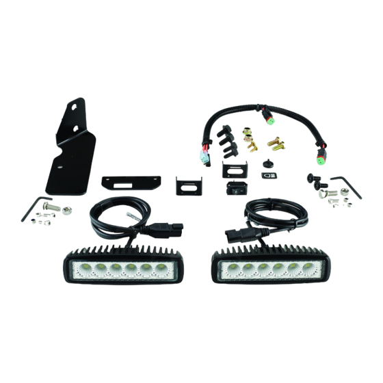
Installation Loose Parts Use the chart below to verify that all parts have been shipped. Description Qty. – No parts required Prepare the machine. LED light Front light bracket Thread-forming screw (5/16 x 3/4 Install the front LED light. inch)—standard platform only Hex-head bolt (5/16 x 3/4 inch) Flange nut (5/16 inch) LED light... - Page 3 Installing the Front LED 3. If you have a machine with a standard platform, install the front light bracket to the front axle tube Light using the 2 thread-forming screws (5/16 x 3/4) provided with the kit (Figure 1. If you have a machine with a MyRide™ platform, remove the existing 2 thread-forming screws (5/16 x 3/4) securing the bumper brackets...
- Page 4 Installing the Side LED Install the Light Switch Light 1. Install the light switch bracket using the 2 self-tapping screws (#10 x 1/2 inch) as shown 1. Secure the side light bracket to the platform Figure using 2 self-tapping hex washer-head bolts as shown in Figure g210324...
- Page 5 Routing the Wire Harness 1. Beginning from the left side, route the wire harness next to the fuel tank, along the main machine wire harness (Figure 2. Continue routing the wire harness underneath the seat plate, moving toward the controls (Figure 10).
- Page 6 6. From the front of the machine, route the wire harness along the right side of the machine and attach the magnetic tie-wrap mount to the right pivot plate (Figure 11). g210473 Figure 11 7. Continue to route the wire harness along the right side of the machine and secure the wire harness to the lift plate using 2 cable ties (Figure 12).
- Page 7 8. Route the wire harness between the right box control plate and the right deck-lift lever (Figure 13). g210691 Figure 13 9. Connect the front light wire-harness lead to the connector on the wire harness for the light kit (Figure 13).
- Page 8 Routing the Wire Harness Overview For Machines with a Standard Platform Figure 14 as an overview for routing the wire harness on a standard platform. g210213 Figure 14...
- Page 9 Routing the Wire Harness Overview For Machines with a MyRide™ Platform Figure 15 as an overview for routing the wire harness on a MyRide™ platform. g210212 Figure 15...
-
Page 10: Testing The Lights
Testing the Lights 1. Turn the key switch to the R position. 2. Test the light switch and verify that the lights are operating correctly. 3. If necessary, adjust the lights so that the light casts as desired. 4. Tighten all loose fasteners to complete the installation. - Page 11 Notes:...