Table of Contents
Advertisement
Quick Links
Quick Start Guide
Quick Start Guide
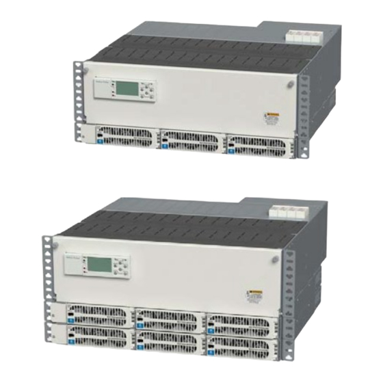
NES-Flex DIN with Integrated AC
NES48-19-4U-AC7-PS3-DIN15B250P-LVBD-ACSPD
NES-Flex DIN with Integrated AC is available as either a one-shelf or two-shelf power system. The system is
factory-configured with LVBD, Pulsar Plus controller, AC circuit breakers, and surge protection. Two shelf system
includes LVLD for 6 priority and 9 non-priority
Tools Required:
•
Torque wrench (0-40Nm)
•
Screw Drivers - Phillips and flat
Step 1 - Mount System
Prepare the system for mounting to the frame.
1. Reposition mounting ears if required - may be moved back (up to
5").
Torque to 2.8 Nm (25 in-lb) - Phillips screwdriver.
Mount the system to the frame.
1. Attach system to frame using minimum of eight screws (four per
side) #12-24 screws (provided).
Step 2 - Ground Chassis
Attach ground cable to rear of system.
Torque to 4 Nm (35 in-lb) - 5/16" (8 mm) socket.
Notes:
1. Lug landing is M5 on 5/8" (16 mm) centers (lug not provided)
2. 10 mm
2
(10 AWG) recommended
3. Some applications may rely on frame mounting screws
for chassis ground omitting the chassis ground cable
Page 1
© 2021 ABB. All rights reserved.
•
Sockets - metric and inch
•
Wire cutters and strippers
•
Cable crimpers
Chassis Ground
Mounting Ears
Inter-Shelf Bracket
Rectifier Shelf
Advertisement
Table of Contents

Related Manuals for ABB NES48-19-4U-AC7-PS3-DIN15B250P-LVBD-ACSPD


Summary of Contents for ABB NES48-19-4U-AC7-PS3-DIN15B250P-LVBD-ACSPD
- Page 1 1. Lug landing is M5 on 5/8” (16 mm) centers (lug not provided) 2. 10 mm (10 AWG) recommended Chassis Ground 3. Some applications may rely on frame mounting screws for chassis ground omitting the chassis ground cable Page 1 © 2021 ABB. All rights reserved.
-
Page 2: Power System
4. Insert wire in terminal blocks in this order: Neutral, Line 1, Line 2, System Recommended Wire Gauge Recommended External 3-Phase AC Breaker 1 shelf system 10 AWG 2 shelf system 8 AWG Page 2 © 2021 ABB. All rights reserved. - Page 3 Slide breaker over bus tabs and engage top DIN rail fully 4. Repeat for additional Battery Breakers, BAT2, etc IMPORTANT - Verify top DIN rail engagement. d. Tighten the breaker bottom connection - #2 Phillips Page 3 © 2021 ABB. All rights reserved.
- Page 4 Fully open the screw connection at breaker top - #2 Phillips. b. Choose any wire from the bundle of black wires behind the breakers. Cut wire. Strip 10 mm (3/8”). Insert wire into breaker load connection. Do not tighten the breaker connection. Page 4 © 2021 ABB. All rights reserved.
- Page 5 Swing the 3/4 of the way. faceplate releases and swings faceplate closed to fully seat the rectifier. outward. Verify the faceplate is latched. Page 5 © 2021 ABB. All rights reserved.
-
Page 6: Step 10 - Initial Start Up
Configuration > Communication Ports > Network Settings > DHCP > mode CLIENT or SERVER Local (Server): LAN connects to a laptop. Local (Server) is a temporary setting. When configuration is complete, return LAN port to Network (Client) mode. Page 6 © 2021 ABB. All rights reserved. - Page 7 Settings Tab > Battery Management for Battery Type and number of battery strings installed Plant Status LEDs Cart port behind door Menu Navigation LCS Display Voltage Test Jacks Front Display Web Home Page Front Display Menu Map Page 7 © 2021 ABB. All rights reserved.
- Page 8 CC848797290 D 6’ ES771A to probe wireset 848719829 D 10’ ES771A to probe wireset CC848791500 G 4’ ES771A to ES771A or controller wireset 848652947 G 10’ ES771A to ES771A or controller wireset Page 8 © 2021 ABB. All rights reserved.
-
Page 9: Alarm Inputs
(MRFA_C) CC848890137 5 ft. CC848890153 5 ft. High Voltage (HV) BK/R CC109157442 15ft CC848865980 15ft R7_C High Voltage_C (HV_C) R/BK CC848817635 50 ft CC848817651 50 ft CC848817643 150 ft CC848817668 150 ft Page 9 © 2021 ABB. All rights reserved. - Page 10 “key” built into the unit will help ensure that the module has been correctly selected. CAUTION : Use of Force During insert to excessive ion, can module to the base result in damage Surge Protectors Red Indicator Window Page 10 © 2021 ABB. All rights reserved.
-
Page 11: Safety Statements
Alarm Signals - Provide external current limiting protection. Rating 60V, 0.5A unless otherwise noted. • Grounding - Connect the equipment chassis directly to ground. In enclosed equipment cabinets connect to the cabinet AC service Page 11 © 2021 ABB. All rights reserved. - Page 12 For technical support and assistance in ordering spares please contact technical support at the following: Email: epis.IDCP-techsupport@abb.com Phone: 1-(877) 546-3243 “Option #2, Option #1) Replacement Surge Protection Modules Commcode Description RU-320-25 Line to Line Module RU-180-25 Line to Gnd Module Notes Page 12 © 2021 ABB. All rights reserved.
- Page 13 Quick Start Guide NOTE Page 13 © 2021 ABB. All rights reserved.
- Page 14 – in whole or in parts – is to purchase orders, the agreed particulars shall prevail. forbidden without prior written consent of ABB. ABB does not accept any responsibility whatsoever for potential errors or possible lack of information in this Copyright©...