Table of Contents
Advertisement
Quick Links
INSTRUCTION MANUAL
TRANSPORTATION & INSTALLATION
1.
Make sure that this instruction manual is delivered to the
final user of Toshiba Machine's industrial robot.
2.
Before installing and operating the industrial robot, read
through and completely understand this manual.
3.
After reading through this manual, keep it nearby for future
reference.
TCR5L/TS2000
Notice
July, 2010
TOSHIBA MACHINE CO., LTD.
NUMAZU, JAPAN
STE 80897-0
Advertisement
Table of Contents

Related Manuals for Toshiba TCR Series


Summary of Contents for Toshiba TCR Series
- Page 1 TRANSPORTATION & INSTALLATION Notice Make sure that this instruction manual is delivered to the final user of Toshiba Machine's industrial robot. Before installing and operating the industrial robot, read through and completely understand this manual. After reading through this manual, keep it nearby for future reference.
- Page 2 TRANSPORTATION & INSTALLATION MANUAL Copyright 2010 by Toshiba Machine Co., Ltd. All rights reserved. No part of this document may be reproduced in any form without obtaining prior written permission from Toshiba Machine Co., Ltd. The information contained in this manual is subject to change without prior notice to effect improvements.
- Page 3 TRANSPORTATION & INSTALLATION MANUAL PREFACE This manual describes how to unpack and install the robot and robot controller. Specifically, it describes how to unpack the shipments containing the robot and controller, how to install them, how to connect wiring and air piping and how to mount a tool on the robot arm.
- Page 4 TRANSPORTATION & INSTALLATION MANUAL CAUTIONS ON SAFETY This manual contains the important information on the robot and controller to prevent injury to the operators and persons nearby, to prevent damage to assets and to assure correct use. Make sure that the following details (indications and symbols) are well understood before reading this manual.
- Page 5 • Be sure to use the master power voltage and power capacity designated by Toshiba Machine. Otherwise, the equipment could be damaged or catch fires. • Be sure to use the designated power cable.
- Page 6 TRANSPORTATION & INSTALLATION MANUAL CAUTION • NEVER lift the robot arm during the transport. Otherwise, an excessive force will be exerted on the mechanical part of the robot, resulting in faults. • For the controller, keep an ample space for air vent. Prohibited Otherwise, the controller will be heated, causing faults.
-
Page 7: Table Of Contents
TRANSPORTATION & INSTALLATION MANUAL Table of Contents Page Section 1 Transportation ................1–1 Unpacking.................... 1–1 Transport ..................... 1–2 1.2.1 Mass and External Dimensions ..........1–2 1.2.2 Transporting the Robot............1–2 1.2.3 Transporting the Controller............. 1–4 Storage ....................1–5 1.3.1 Cautions on Robot Storage ............ 1–5 1.3.2 Cautions on Robot Controller Storage........ - Page 8 TRANSPORTATION & INSTALLATION MANUAL Page Section 3 System Connection ................ 3–1 Cable Connection ................3–1 3.1.1 Connector Layout of the Controller......... 3–1 3.1.2 Connecting Power Cable............3–2 3.1.3 Connecting Motor Cable............3–3 3.1.4 Connecting Encoder Cable............. 3–3 3.1.5 Connecting Robot Control Signal Cable ......... 3–3 3.1.6 Inserting and Removing Connectors ........
-
Page 9: Transportation
TRANSPORTATION & INSTALLATION MANUAL Section 1 Transportation Unpacking The robot and controller are shipped separately in wooden crates and corrugated cardboards. The packaging state of the controller is shown in Fig. 1.1. The teach pendant and other accessories including instruction manuals are packed separately. -
Page 10: Transport
TRANSPORTATION & INSTALLATION MANUAL Transport Carefully move the robot and controller to avoid excessive impact (9.8 m/s or over) or vibration from being exerted on them. If the equipment are subject to vibration over a long period of time, be sure to completely tighten all nuts and screws. When relocating the equipment at another place, apply the cushions as originally set, then put the equipment back into the wooden crates and corrugated cardboards. - Page 11 TRANSPORTATION & INSTALLATION MANUAL Lift up the robot carefully, using the crane. Next, disconnect the robot body from the transport fixtures to carry the robot. Remove the hexagon socket head cap screws and washers, then mount the M10 eyebolts in the screw holes instead. Remove the arm clamps and move so that the arms can overlap each other.
-
Page 12: Transporting The Controller
TRANSPORTATION & INSTALLATION MANUAL CAUTION • Use the wires which can well withstand the robot mass. • The robot will tilt more or less when lifted. Carefully lift it up. • When raising and lowering the robot, take careful precautions not to exert any excessive impact (9.8 m/s or over) on the robot. -
Page 13: Storage
TRANSPORTATION & INSTALLATION MANUAL Storage Both the robot and controller should not be stored for a long period of time after unpacked. When this is unavoidable, however, be sure to observe the following cautions on storage. 1.3.1 Cautions on Robot Storage CAUTION •... -
Page 14: Installation
9.8 m/s or less Dust No inductive dust should be involved. Consult with Toshiba Machine first if you have to use the robot and controller in a hostile environment. No corrosive gas or combustible gas should be involved. Sunlight The robot and controller should not be exposed to direct sunlight. -
Page 15: Installing The Robot
TRANSPORTATION & INSTALLATION MANUAL Installing the Robot Before actually installing the robot, you should review a layout, fully considering the working envelope, coordinate system and space for maintenance. 2.2.1 External Dimensions See the external view drawing of the robot attached to the specifications. 2.2.2 Working Envelope See the external view drawing of the robot attached to the specifications. - Page 16 TRANSPORTATION & INSTALLATION MANUAL Fig. 2.1 External view STE 80897 – 2–3 –...
-
Page 17: Origin Posture And Coordinate System Of The Robot
TRANSPORTATION & INSTALLATION MANUAL 2.2.3 Origin Posture and Coordinate System of the Robot The origin posture and coordinate system of the robot are exemplified in Fig. 2.2. Rotation 0(deg) direction Axis 2 (+) Axis 1 (+) Axis 4 (–) Axis 4 (+) Axis 1 (–) Axis 3 (+) Axis 3 (-) -
Page 18: Robot Installation Procedures
TRANSPORTATION & INSTALLATION MANUAL 2.2.4 Robot Installation Procedures The robot is secured, using the set holes on the robot base. The robot base set areas should be rigid enough and their surfaces should be machined with flatness accuracy as small as 0.2 or less. CAUTION •... -
Page 19: Installing The Controller
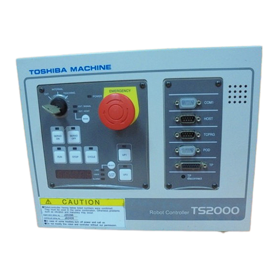
TRANSPORTATION & INSTALLATION MANUAL Installing the Controller 2.3.1 External Dimensions Fig. 2.4 shows the external dimensions of the TS2000 robot controller. Top view Front view Side view Rear view Fig. 2.4 External view of TS2000 controller STE 80897 – 2–6 –... -
Page 20: Rack Mounting Dimensions
TRANSPORTATION & INSTALLATION MANUAL 2.3.2 Rack Mounting Dimensions When installing the robot controller in the rack, set the side brackets, using the screw holes on both ends of the front panel, then secure the controller to the rack. (Side brackets [1] in Fig. 2.5 are optional.) 319.4 4... - Page 21 TRANSPORTATION & INSTALLATION MANUAL As the cable connectors are connected to the rear side of the controller, keep a space of 110 mm on the rear side. To perform maintenance of the controller, the upper cover is removed. (See Fig. 2.6.) When installing the controller, fully consider the controller maintenance.
- Page 22 TRANSPORTATION & INSTALLATION MANUAL On the front side of the controller, a clearance of about 90 mm should be kept for connecting the connector of the teach pendant. Even if the teach pendant is not used, a clearance of about 50 mm is required for connecting a dummy plug.
-
Page 23: Cautions On Direct Installation
TRANSPORTATION & INSTALLATION MANUAL 2.3.4 Cautions on Direct Installation When two (2) or more controllers are used, keep a clearance of 50 mm or over in the right and left directions between the controllers and a clearance of 100 mm or over in the upper direction of each controller. -
Page 24: Cautions On Handling Of Teach Pendant
TRANSPORTATION & INSTALLATION MANUAL Cautions on Handling of Teach Pendant When handling the teach pendant, observe the following precautions. CAUTION • DO NOT drop the teach pendant or hit it against anything. • DO NOT pull the cable coming out of the teach pendant. •... -
Page 25: Safety Measures
TRANSPORTATION & INSTALLATION MANUAL Safety Measures When installing the robot, provide sufficient space to carry out the work safely. Clarify the hazard zone, and provide safety fences to prevent anyone from entering the zone easily. The hazard zone is the zone near the working envelope of the robot, where a hazardous state could occur if a person enters. -
Page 26: Position Detector Backup Batteries
TRANSPORTATION & INSTALLATION MANUAL Position Detector Backup Batteries The robot has batteries to back up positional information on position detectors in its base. Unless the robot is used for a long period of time, the battery voltage will drop and the positional data of the origin will be lost. Also, if the battery voltage for backup of the X8HC printed board SRAM of the controller has dropped, absolute position data set by the user will be lost. -
Page 27: System Connection
TRANSPORTATION & INSTALLATION MANUAL Section 3 System Connection Cable Connection This section describes the various types of cables and connectors and explains how these are to be connected. 3.1.1 Connector Layout of the Controller The cables connected to the TS2000 robot controller are shown in Fig. 3.1 Power cable Motor cable Encoder cable... -
Page 28: Connecting Power Cable
TRANSPORTATION & INSTALLATION MANUAL 3.1.2 Connecting Power Cable "CN1" (Fig. 3.1–[1]; Plug connector included) The power cable is used to supply the main power to the controller. Table 3.1 Power supply specifications Item Specifications Power supply Single phase, AC 190 ~ 250 V, 50/60 Hz ±1 Hz Power capacity 1.7 kVA Instantaneous power... -
Page 29: Connecting Motor Cable
TRANSPORTATION & INSTALLATION MANUAL CAUTION • Unless the main power is normally supplied to the controller due to phase defect or voltage drop, "8–027 Slow Charge error" occurs. When this happens, make sure that the master power voltage at the controller power connector satisfies the specified input power of the controller, and that the same master power voltage is stabilized. - Page 30 TRANSPORTATION & INSTALLATION MANUAL Circular connectors: CN1, CN2 Completely push the connector on the cable side into the connector on the controller side. Then turn CW and tighten the cable side lock screw. If it is loosened, an accident due to contact failure of connector will occur. To remove the connector, turn CCW and loosen the lock screw, then draw out the cable side connector.
-
Page 31: List Of Connector Terminal Arrangement Examples
TRANSPORTATION & INSTALLATION MANUAL 3.1.7 List of Connector Terminal Arrangement Examples Power cable connector CN1 Connects to controller. Type: JL04V–2E18–10PE–B Maker: Japan Aviation Electronics Industry ⎤ B — Single phase, AC 190 ~ 250 , 50/60 Hz ⎦ D — Grounding (Grounding with grounding resistance of 100 Ω or less) DANGER •... - Page 32 TRANSPORTATION & INSTALLATION MANUAL Robot control signal cable connector CN4 Connects to controller. Type: PCR–E20LMD 11 12 13 14 15 16 17 18 19 20 Maker: Honda Tsushin Kogyo External input signal cable connector CN5 Connects to controller. 1 2 3 4 5 6 7 8 9 10 11 12 13 16 17 18 19 Type: XM2C–3712–112 20 21 22 23 24 25 26 27 28 29...
-
Page 33: Controller Connector Signals
TRANSPORTATION & INSTALLATION MANUAL Controller Connector Signals 3.2.1 Connector Signal Connection Diagrams The diagrams showing which signals correspond to which terminals are shown in Section 2 of the Interface Manual. 3.2.2 Jumpers for Safety Related Signals The following system input signals are provided to serve for the safety purpose. System input signals CN5–16 (STOP) - Page 34 TRANSPORTATION & INSTALLATION MANUAL CAUTION If the signals of SVOFF and emergency stop contacts 1, 2 are jumpered, the controller servo power cannot be turned on. Unless the CYCLE signal is jumpered, the controller enters the cycle operation mode. Unless the LOW_SPD signal is jumpered, the robot is operated at low speed during automatic operation.
-
Page 35: Separating Control Panel From Controller
TRANSPORTATION & INSTALLATION MANUAL Separating Control Panel from Controller 3.3.1 Removing Control Panel Remove the control panel in the following manner. Loosen the four (4) screws at the four (4) corners, which secure the control panel. Remove these screws, then carefully draw out the control panel toward your side. (Be careful of the cable connected on the rear side.) Controller ... -
Page 36: Cable Between Controller And Control Panel
TRANSPORTATION & INSTALLATION MANUAL 3.3.2 Cable between Controller and Control Panel The cable required to connect the control panel and controller when they are installed separately can be provided optionally. 3.3.3 Control Panel Mounting Dimensions The dimensions of mounting the control panel are shown in Fig. 3.5. Cross truss head screws (ø3×6, ZN3–B) are used. -
Page 37: Mounting Dummy Panel On Controller
TRANSPORTATION & INSTALLATION MANUAL 3.3.4 Mounting Dummy Panel on Controller When the control panel has been disengaged from the controller, mount a dummy panel on the place where the control panel was set before. The dummy panel, set parts, etc. are provided optionally. Connect the cable connector which was disconnected when separating the controller from the control panel, to the rear side of the dummy panel, then screw both ends of the connector. -
Page 38: Dimensions When Separating Control Panel
TRANSPORTATION & INSTALLATION MANUAL 3.3.5 Dimensions when Separating Control Panel Fig. 3.7 shows the connections of the control panel and dummy panel. Provide a clearance of about 50.6 mm on the rear side of the separated control panel. When the cable is connected to the dummy panel of the controller, provide a clearance of 80 mm or so in front of the controller as the cable connector sticks out of the panel surface. -
Page 39: Hand Interface
TRANSPORTATION & INSTALLATION MANUAL Section 4 Hand Interface Hand Attachment Dimensions of the hand attachment are shown in Fig. 4.1. 4xM5 depth 9 Fig. 4.1 Dimensions of hand attachment Wiring and Piping for Hand For detail of the wiring and the piping for the hand, please refer to the robot specifications. - Page 40 TRANSPORTATION & INSTALLATION MANUAL APPROVED BY: CHECKED BY: PREPARED BY: STE 80897 – 4–2 – ....