
Related Manuals for Fujitsu SK-MB9EF120-002


Summary of Contents for Fujitsu SK-MB9EF120-002
- Page 1 Fujitsu Semiconductor Europe GmbH FMEMCU-UG-9E0010-11 User Guide FCR4 FAMILY FCR4 CLUSTER SERIES EVALUATION BOARD SK-MB9EF120-002,-003 USER GUIDE...
-
Page 2: Revision History
“Reference”. This document contains 30 pages. Abbreviations Digital Volt-Meter FSEU Fujitsu Semiconductor Europe GmbH Graphic Device Controller Microcontroller Unit ARM® registered trademark of ARM Ltd. APIX® Automotive Pixel Link is a registered trademark of INOVA Semiconductors GmbH... -
Page 3: Warranty And Disclaimer
The use of the deliverables (e.g. software, application examples, target boards, evaluation boards, starter kits, schematics, engineering samples of IC’s etc.) is subject to the conditions of Fujitsu Semiconductor Europe GmbH (“FSEU”) as set out in (i) the terms of the License Agreement and/or the Sale and Purchase Agreement under which agreements the Product has been delivered, (ii) the technical descriptions and (iii) all accompanying written materials. -
Page 4: Table Of Contents
3.3 Lifesigns ..........................13 4 CONFIGURATION AND TEST-POINTS ..................14 4.1 Jumpers ..........................14 4.2 Headers ..........................15 4.3 Test-Points .......................... 16 4.4 Status Display ........................16 5 CONNECTORS ........................... 17 - 4 - © Fujitsu Semiconductor Europe GmbH UG-9E0010-11... - Page 5 6 TROUBLE SHOOTING ....................... 24 7 RELATED PRODUCTS ......................25 8 INFORMATION ON THE WEB ....................26 9 EU-KONFORMITÄTSERKLÄRUNG / EU DECLARATION OF CONFORMITY ....... 28 10 CHINA-ROHS REGULATION ....................29 11 RECYCLING ..........................30 © Fujitsu Semiconductor Europe GmbH - 5 - UG-9E0010-11...
-
Page 6: Overview
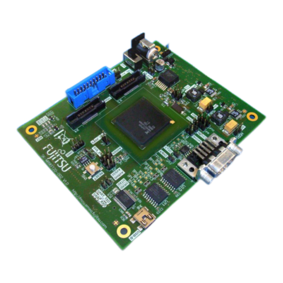
1 Overview 1.1 Abstract The SK-MB9EF120-002,-003 is a quick evaluation board for the Fujitsu FCR4 Cluster series flash microcontroller MB96EF126 (Calypso). It can be used stand-alone for software development and testing or as a simple target board to work with the emulator system. -
Page 7: Contents
ARM standard 20 pin IDC JTAG connector Trace-probe connector for up to 32-bit wide tracing Kit contents Starterkit-board. USB-A to Mini-B cable. Screws with spacers to mount onto a carrier-board or place on the table. © Fujitsu Semiconductor Europe GmbH - 7 - UG-9E0010-11... -
Page 8: Hardware
12V external DC power supply, 5V, 3V3 and 1V2 voltage regulators, S1 power switch Power-LEDs for the 5V0, 3V3 and 1V2 power rails, SW1 Reset-button, Reset-LED X2, X3, X4: debug and trace ports for ARM-standard connectors - 8 - © Fujitsu Semiconductor Europe GmbH UG-9E0010-11... -
Page 9: Bottom View
(5V0 → 3V3 → 1V2). Power-down/disconnect of power- domains and/or -rails is not supported. All regulators are supplied from the input-rail Vin_prot (filtered input voltage, no regulator-staggering). © Fujitsu Semiconductor Europe GmbH - 9 - UG-9E0010-11... -
Page 10: Input Stage
3V3-domain. The MCU reset-input is located in the VDP5-domain, so an open-drain-driver (non- inverting) is used which buffers the signal and has a pull-up resistor to VDP5 at the output, generating RST_X_VDP5. - 10 - © Fujitsu Semiconductor Europe GmbH UG-9E0010-11... -
Page 11: Mcu Clocks
It provides data-storage for applications. The second flash is of the same type, but connects to the GFXSPI-port which can be accessed by the graphics-controller without CPU intervention. The actual device chosen supports Quad-SPI mode at up to 80MHz, resulting in a max. data rate of 40MB/s. © Fujitsu Semiconductor Europe GmbH - 11 - UG-9E0010-11... -
Page 12: Expansion Connectors
On the bottom-side, there are two connectors (CN1, CN2). All MCU ports are available here, along with power-supply and additional control-signals like reset. Layout and placement of the SK-MB9EF120-002,-003 allow to plug a Fujitsu Multi-I/O board ADA- FCR4-MULTIIO-001) under the board, providing direct access to the ports via standard-raster headers along with other features. -
Page 13: Installation
SVS' trigger-level and drop below, eg. if more current is drawn by a device. Use HDR1-3 and 6 to measure voltages. Never short these Headers! © Fujitsu Semiconductor Europe GmbH - 13 - UG-9E0010-11... -
Page 14: Configuration And Test-Points
4 Configuration and Test-Points 4.1 Jumpers The SK-MB9EF120-002,-003 provides multiple options to access signals and configure its properties. For this, it has two variants of jumpers: (regular) Jumpers consist of two or three pin-headers and a small cap. They can be changed without extra tools. -
Page 15: Headers
3-pin wide HDR4, 5 GND top B-14, O-11 reference for scopes, logic-analyzers, voltmeters, etc. (each) 1.2V rail voltage measuring header. HDR6 2-pin wide top E/F-9 Do not inject any current here! © Fujitsu Semiconductor Europe GmbH - 15 - UG-9E0010-11... -
Page 16: Test-Points
Name Color Description (when lit) Position orange 5V0 rail up top P-15 yellow 3V3 rail up top O/P-15 green 1V2 rail up (driven by 3V3-rail) top O-15 reset active top O/P-14 - 16 - © Fujitsu Semiconductor Europe GmbH UG-9E0010-11... -
Page 17: Connectors
MCU ports as well as reset and power supplies from the SK-board. Signals are always routed to these connectors, even if they are used on the SK-MB9EF120-002,-003 themselves. When using a signal on a plug-under board which is also connected to an on-board peripheral or connector, it must be disconnected from the on-board resource by pulling the corresponding jumper. - Page 18 P0_33 P0_9 P0_34 P0_10 P0_35 P0_11 P0_36 P0_12 P1_16 P0_13 P1_17 P0_14 P1_18 P0_15 P1_19 P0_40 P1_20 P0_41 P1_21 P0_42 P1_22 P0_24 P1_23 P0_43 P0_25 P0_22 P0_23 P0_44 P0_50 P0_46 P0_51 - 18 - © Fujitsu Semiconductor Europe GmbH UG-9E0010-11...
-
Page 19: Cn2 Pinout
P1_26 P1_32 P1_41 P1_31 P2_0 P2_2 P2_1 P2_3 P0_63 P0_62 P2_4 P2_6 P2_5 P2_7 P1_30 P2_8 P2_10 P1_28 P2_9 P2_11 P1_29 P2_12 P2_14 P2_13 P2_15 P2_16 P2_18 P2_17 P2_19 P2_20 P2_22 © Fujitsu Semiconductor Europe GmbH - 19 - UG-9E0010-11... -
Page 20: Debug Connector (X2)
RTCK is deactivated by default. To enable it, a 0R0 resistor (soldering jumper, see there) must be soldered. The feature is only required for high-speed clocking. This connector must not be used at the same time as the trace-connector. - 20 - © Fujitsu Semiconductor Europe GmbH UG-9E0010-11... -
Page 21: Trace Connectors (X3, X4)
Trace data TRACE12 Trace data TRACE11 Trace data TRACE10 Trace data TRACE9 Trace data TRACECTL Trace Control TRACE8 Trace data TRACE0 Trace data For the JTAG-signals see section 6.2 for details. © Fujitsu Semiconductor Europe GmbH - 21 - UG-9E0010-11... -
Page 22: Extension Trace-Connector (X4)
This is a standard DC-Plug with inner pin (2.1mm dia) and outer shell. The connector is used to plug an external DC power supply with 12V/1.5A DC to the evaluation board. Caution: the pin has positive supply, while the shell is negative/GND. - 22 - © Fujitsu Semiconductor Europe GmbH UG-9E0010-11... -
Page 23: Can-Bus Connector (X5)
Tied to GND via 1M0||100nF Check jumpers when using USB/UART to have the signals connected to the bus-driver. Also make sure the related ports are not connected elsewhere via the B2B connectors. © Fujitsu Semiconductor Europe GmbH - 23 - UG-9E0010-11... -
Page 24: Trouble Shooting
SK-MB9EF120-002,-003 Trouble shooting 6 Trouble shooting - 24 - © Fujitsu Semiconductor Europe GmbH UG-9E0010-11... -
Page 25: Related Products
Base board for using of MCU board with several IO interfaces like CAN, LIN, MediaLB, Ethernet, Video and Audio accessing ADA-FCR4-CLUSTER-001 Automobile dashboard sample with stepper-motors and other functions (requires Multi-IO board) ADA-DISP2MULTIIO-001 Display-demonstration board for Multi-IO board. © Fujitsu Semiconductor Europe GmbH - 25 - UG-9E0010-11... -
Page 26: Information On The Web
Datasheets and Hardware Manuals, Support Tools (Hard- and Software) http://mcu.emea.fujitsu.com/ Power Management Products http://www.fujitsu.com/emea/services/microelectronics/powerman/index.html For more information about FUJITSU SEMICODUCTOR http://emea.fujitsu.com/semiconductor Information about and software drivers for the peripheral devices used on the starter kit can be found on the following Internet pages: ... - Page 27 SK-MB9EF120-002,-003 Information on the Web Quartz Crystal Units http://www.ndk.com http://www.microcrystal.ch Flash Memory http://www.spansion.com © Fujitsu Semiconductor Europe GmbH - 27 - UG-9E0010-11...
-
Page 28: Eu-Konformitätserklärung / Eu Declaration Of Conformity
9 EU-Konformitätserklärung / EU declaration of conformity Hiermit erklären wir, Fujitsu Semiconductor Europe GmbH, Pittlerstrasse 47, 63225 Langen, Germany dass dieses Board aufgrund seiner Konzipierung und Bauart sowie in den von uns in Verkehr gebrachten Ausführung(en) den grundlegenden Anforderungen der EU-Richtlinie 2004/108/EC „Elektromagnetische Verträglichkeit“... -
Page 29: China-Rohs Regulation
SK-MB9EF120-002,-003 China-RoHS regulation 10 China-RoHS regulation This board is compliant with China RoHS. © Fujitsu Semiconductor Europe GmbH - 29 - UG-9E0010-11... -
Page 30: Recycling
According to the European WEEE-Directive and its implementation into national laws we take this device back. For disposal please send the device to the following address: Fujitsu Semiconductor Europe GmbH Warehouse/Disposal Monzastraße 4a D-63225 Langen GERMANY -- END -- - 30 - © Fujitsu Semiconductor Europe GmbH UG-9E0010-11...