Sign In
Upload
Manuals
Brands
Komatsu Manuals
Air Conditioner
WA900-3E0
Komatsu WA900-3E0 Manuals
Manuals and User Guides for Komatsu WA900-3E0. We have
3
Komatsu WA900-3E0 manuals available for free PDF download: Operation & Maintenance Manual, Shop Manual, Brochure
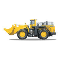
Komatsu WA900-3E0 Operation & Maintenance Manual (336 pages)
Wheel Loader
Brand:
Komatsu
| Category:
Front End Loaders
| Size: 13.43 MB
Table of Contents
Foreword
16
Foreword
5
Safety Information
5
Noise Emission Levels
7
Vibration Levels
8
Introduction
10
Visibility from Operator's Seat
11
Visibility in Immediate Area
11
12-M Radius Visibility
12
Necessary Information
13
Product Identification Number (Pin)/Machine Serial No. Plate
13
Epa Regulations, Engine Number Plate
13
Position of Service Meter
14
Machine Serial Number Plate
15
Table of Contents
16
Safety
23
Safety 2
24
Safety Labels
26
Location of Safety Labels
27
Safety Labels
28
General Precautions
33
Precautions for Operation
43
Starting Engine
43
Checks before Starting Engine
43
Precautions When Starting
43
Operation
44
Precautions in Cold Areas
44
Checks before Operation
44
Precautions When Traveling in Forward or Reverse
44
Precautions When Traveling
45
Traveling on Slopes
46
Prohibited Operations
47
Precautions When Operating
47
Methods of Using Brake
48
Operate Carefully on Snow
48
Parking Machine
49
Transportation
50
Loading and Unloading
50
Shipping
50
Battery
51
Battery Hazard Prevention
51
Starting with Booster Cables
52
Towing
53
Precautions for Maintenance
54
Warning Tag
54
Keep Work Place Clean and Tidy
54
Appoint Leader When Working with Others
54
Stop Engine before Carrying out Maintenance
55
Two Workers for Maintenance When Engine Is Running
56
Proper Tools
57
Accumulator
58
Personnel
58
Attachments
58
Work under the Machine
59
Noise
59
Precautions When Using Hammer
59
Repair Welding
59
Removing Battery Terminal
59
Precautions with High-Pressure Oil
60
Precautions for High-Pressure Fuel
60
Handling High-Pressure Hoses
60
Waste Materials
61
Maintenance of Air Conditioner
61
Compressed Air
61
Periodic Replacement of Safety Critical Parts
61
Precautions with Tires
62
Operation
63
General View
64
General View of Machine
64
General View of Controls and Gauges
65
Explanation of Components
68
Machine Monitor
68
Monitor System
68
Warning Display
71
Meter Display Portion
77
Switches
84
Control Levers, Pedals
98
Main Monitor Tilt Lever
104
Cap with Lock
105
Method of Opening and Closing Cap with Lock
105
Frame Lock Bar
106
Towing Pin
107
Engine Shut-Down Switch
107
Fuel Stop Lever
107
Backup Alarm
107
Cab Door Open Lock
108
Handling Cab Wiper
108
Preventing Damage to Wiper Arm Bracket
108
Replacing Cab Wiper
108
Dust Indicator
109
Fuse
109
Fuse Capacity and Name of Circuit
110
Circuit Breaker
111
Slow Blow Fuse
111
Lunch Box Tray
112
Tool Box
112
Grease Pump
112
Location of Fire Extinguisher
113
Power Outlet
113
Am/Fm Radio-Cassette Stereo
114
Explanation of Components
114
Method of Operation
119
Precautions When Using
121
Air Conditioner
122
General Locations and Function of Control Panel
122
Method of Operation
125
Use Air Conditioner with Care
126
Air Conditioner Maintenance
126
Cool Box
126
Handling Wireless
127
Operation
128
Check before Starting Engine, Adjust
128
Walk-Around Check
128
Check before Starting
131
Maintenance Schedule Chart 4
243
Initial 250 Hours Service (Only after the First 250 Hours)
245
Lubricating
245
Replace Transmission Oil Filter Element
245
When Required
246
Check, Clean, or Replace Air Cleaner Element
246
Clean Inside of Cooling System
248
Check Transmission Oil Level, Add Oil
252
Check Axle Oil Level, Add Oil
253
Clean Axle Case Breather
253
Check Window Washing Fluid Level, Add Fluid
254
Clean Air Conditioner Condenser
254
Clean Radiator, Oil Cooler, Aftercooler Fins
255
Replace Bucket Teeth
256
Lubricating
257
Check Air Conditioner
258
Bleeding Air from Brake Hydraulic Circuit
259
Replace Slow Blow Fuse
260
Bleeding Air from Hydraulic Tank
261
Replace Fan Belt, Adjust Auto-Tensioner
263
Selection and Inspection of Tires
265
Check before Starting
267
Drain Water, Sediment from Fuel Tank
268
Every 50 Hours Service
268
Lubricating
269
Check Oil Level in Hydraulic Tank, Add Oil
271
Clean Element in Air Conditioner Fresh Air Filter
272
Every 100 Hours Service
269
Every 250 Hours Service
273
Check Battery Electrolyte Level
273
Check Parking Brake
274
Check Alternator Belt Tension, Adjust
275
Check Air Conditioner Compressor Belt Tension, Adjust
276
Check for Loose Wheel Hub Nuts, Tighten
277
Checking Function of Accumuulator
277
Every 500 Hours Service
278
Clean Element in Air Conditioner Recirculation Filter
277
Change Oil in Engine Oil Pan, Replace Engine Oil Filter Cartridge
278
Replace Fuel Pre-Filter Cartridge
280
Replace Transmission Oil Filter Element
282
Check Fan Belt for Wear
283
Every 1000 Hours Service
284
Lubricate Center Drive Shaft
283
Change Oil in Transmission Case, Clean Strainer
284
Clean Transmission Case Breather
285
Replace Fuel Main Filter Cartridge
286
Lubricating
288
Tighten Rops Canopy
290
REPLACE CORROSION RESISTOR CARTRIDGE (Only When Corrosion Resistor Cartridge Is Used)
291
Check of Engine Air Intake Piping Clamps for Looseness
292
Every 2000 Hours Service
293
Change Oil in Hydraulic Tank, Replace Hydraulic Filter Element
293
Clean Hydraulic Tank Strainer
296
Replace Hydraulic Tank Breather Element
297
Change Axle Oil
298
Change Brake Oil
300
Replace Filter Element in Brake Oil Tank
301
Clean Ppc Circuit Strainer
302
Replace Brake Oil Tank Breather
302
Replace Element in Air Conditioner Recirculation Air Filter, Fresh Air Filter
302
Check Alternator, Starting Motor
303
Check Brake Disc Wear
303
Check Engine Valve Clearance, Adjust
303
Checking Function of Accumulator
304
Every 4000 Hours Service
305
Check Fan Pulley and Tension Pulley
305
Check Starting Motor
305
Check Water Pump
305
Check for Loose Engine High-Pressure Piping Clamps, Hardening of Rubber
306
Checking for Missing Fuel Spray Prevention Cap, Hardening of Rubber
307
Every 8000 Hours Service
308
Overhaul Starting Motor and Alternator
308
Replace Engine High-Pressure Piping Clamps
308
Replace Fuel Spray Prevention Cap
308
Advertisement
Komatsu WA900-3E0 Shop Manual (170 pages)
Brand:
Komatsu
| Category:
Excavators
| Size: 3.68 MB
Table of Contents
Index and Foreword
2
Table of Contents
3
Table of Contents
4
Foreword
7
Before Reading this Manual
7
Specification Specification
10
Specification Dimension Drawing
10
Specification
10
Specifications
11
Weight Table
14
Table of Fuel, Coolant and Lubricants
16
Structure and Function
20
Cooling System and Related Devices
22
Cooling System
22
Hydraulic System
24
Power Ladder System
24
Electrical System
29
Power Ladder Controller
29
Rear View Monitor System
38
Engine Service Monitor System
41
Parking Brake Circuit
43
Sensor
45
Standard Value Table
48
Standard Value Table for Chassis
50
Standard Value Table for Electrical System
51
Testing and Adjusting
52
Inspection and Adjustment of Potentiometer
54
Testing and Adjusting
54
Ladder Position Calibration Procedure
55
Procedure for Testing Diodes
57
Troubleshooting
58
General Information on Troubleshooting
61
Classification and Procedures of Troubleshooting
61
Failure Codes Table
62
General Information on Troubleshooting
62
Fuse Locations
64
Troubleshooting by Failure Code
66
Failure Code [D1EMKA] (Disconnection of Parking Brake Interlock Relay)
66
Failure Code [D1EMKB] (Ground Fault of Parking Brake Interlock Relay)
68
Failure Code [D1EMKY] (Hot Short of Parking Brake Interlock Relay)
69
Failure Code [D1EPKA] (Disconnection of Ladder Drive Pump Relay)
70
Failure Code [D1EPKB] (Ground Fault of Ladder Drive Pump Relay)
71
Failure Code [D1EPKY] (Short Circuit of Ladder Drive Pump Relay)
72
Failure Code [D1EQKY] (Ladder Operation Alarm Relay Output Hot Short Circuit)
73
Failure Code [D1EQKZ]
74
Open Circuit, Ground Fault)
74
Failure Code [D1ERKB] (Ladder Raise Solenoid Output Ground Fault)
75
Failure Code [D1ERKZ]
76
Open Circuit, Hot Short Circuit)
76
Failure Code [D1ESKB] (Ladder Lower Solenoid Output Ground Fault)
77
Failure Code [D1ESKZ]
78
Open Circuit, Hot Short Circuit)
78
Failure Code [DBL0KR] (Power Ladder Controller CAN-NET Signal Line Open Circuit)
79
Failure Code [DBL0KT] (Non-Volatile Memory Write Error)
83
Failure Code [DBL1KK] (Power Low Error: Battery Direct)
84
Failure Code [DBL2KK] (Solenoid Power Low Error)
86
Failure Code [DDB6KZ] (Parking Brake System Abnormality)
88
Failure Code [DDDGKY] (Ladder Operation Switch Hot Short Circuit)
90
Failure Code [DDDKKY] (Ladder Raise Operation Switch Hot Short Circuit)
95
Failure Code [DDDLKY] (Ladder Lower Operation Switch Hot Short Circuit)
96
Failure Code [DK5VKX] (Ladder Angle Sensor Abnormality: out of Range)
98
Failure Code [DK5VMA] (Power Ladder System Abnormality)
100
Failure Code [DUM9KY] (Ladder Indicator Output Hot Short Circuit)
103
Failure Code [DUM9KZ] (Ladder Indicator Output Abnormality: Open Circuit, Hot Short Circuit)40
104
Failure Code [DV00KY] (Ladder Interlock Caution Output Hot Short Circuit)
105
Failure Code [DV00KZ]
106
Open Circuit, Ground Fault)
106
Failure Code [DWNLKA] (Ladder Cushion Valve Output Open Circuit)
107
Failure Code [DWNLKB] (Ladder Cushion Valve Output Ground Fault)
108
Failure Code [DWNLKY] (Ladder Cushion Valve Output Hot Short Circuit)
109
Troubleshooting of Electrical System (E-Mode)
110
Power Ladder Does Not Operate
110
Brake Oil Temperature Warning Keeps Lighting
113
Parking Brake Does Not Operate (as Emergency Brake)
115
Parking Brake Is Applied While Machine Is Traveling
119
Parking Brake Is Released as Starting Switch Is Turned to on Position
122
Troubleshooting of Hydraulic and Mechanical System (H-Mode)
124
Power Ladder Does Not Move or Its Speed Is Low
124
Fan of ADD Cooler Does Not Rotate
125
Troubleshooting of Maintenance Monitor System (K Mode)
126
Maintenance Monitor System
126
Hydraulic Oil Level Gauge Flashes
128
Troubleshooting for Machine Monitor (M-Mode)
131
Rear View Monitor Does Not Operate
131
While Clearance Lamp Is Turned On, Illuminance of Rear View Monitor Remains Dark
134
Rear View Monitor Does Not Work in Reverse-Interlock Mode
135
Illuminance of Rear View Monitor Cannot be Adjusted
137
Optional Controller Error and Real-Time Monitor Sreen Are Not Displayed on Engine Service Monitor
139
Engine Compartment Lamp Does Not Light up
141
Step Lamp Does Not Light up
144
Diagrams and Drawings
146
Hydraulic Circuit Diagram
148
Symbols Used in Hydraulic Circuit Diagram
148
Power Train Hydraulic Circuit Diagram
152
Brake, Power Ladder and Additional Cooler Hydraulic Circuit Diagram
153
Work Equipment Hydraulic Circuit Diagram
154
Electrical Circuit Diagram
155
Symbols Used in Electric Circuit Diagram
155
Electrical Circuit Diagram
156
Connector Arrangement Diagram
161
Komatsu WA900-3E0 Brochure (6 pages)
WHEEL LOADER
Brand:
Komatsu
| Category:
Front End Loaders
| Size: 0.96 MB
Advertisement
Advertisement
Related Products
Komatsu WA1200-3
Komatsu WA800-3E0
Komatsu Avance Loader WA900-3
Komatsu Breathesafe WA900-3EO
Komatsu WA95-3
Komatsu WA20-2
Komatsu WA150PZ-5
Komatsu WA65-3
Komatsu WA600-3
Komatsu WA480-5
Komatsu Categories
Excavators
Trucks
Compact Loader
Construction Equipment
Tractor
More Komatsu Manuals
Login
Sign In
OR
Sign in with Facebook
Sign in with Google
Upload manual
Upload from disk
Upload from URL