ABB REB670 Applications Manual
Relion 670 series busbar protection
Hide thumbs
Also See for REB670:
- Applications manual (508 pages) ,
- Commissioning manual (196 pages) ,
- Operator's manual (116 pages)

Related Manuals for ABB REB670


Summary of Contents for ABB REB670
- Page 1 — R E L I O N ® 670 SERIES Busbar protection REB670 Version 2.2 ANSI Application manual...
- Page 3 Document ID: 1MRK 505 370-UUS Issued: October 2017 Revision: A Product version: 2.2.1 © Copyright 2017 ABB. All rights reserved...
- Page 4 Copyright This document and parts thereof must not be reproduced or copied without written permission from ABB, and the contents thereof must not be imparted to a third party, nor used for any unauthorized purpose. The software and hardware described in this document is furnished under a license and may be used or disclosed only in accordance with the terms of such license.
- Page 5 In case any errors are detected, the reader is kindly requested to notify the manufacturer. Other than under explicit contractual commitments, in no event shall ABB be responsible or liable for any loss or damage resulting from the use of this manual or the application of the equipment.
- Page 6 (EMC Directive 2004/108/EC) and concerning electrical equipment for use within specified voltage limits (Low-voltage directive 2006/95/EC). This conformity is the result of tests conducted by ABB in accordance with the product standard EN 60255-26 for the EMC directive, and with the product standards EN 60255-1 and EN 60255-27 for the low voltage directive.
-
Page 7: Table Of Contents
Control and monitoring functions............42 Communication..................47 Basic IED functions.................49 Section 3 Configuration............... 51 Description of configuration REB670............51 Available ACT configurations for pre-configured REB670....51 Configuration X01................51 Configuration X02................52 Configuration X03................52 Description of 3 ph package A20A............ 52 Description of 3 ph package A31A............ 54 Description of 1 ph package B20A............ - Page 8 Parameter management ..............105 Front communication............... 106 Section 6 Differential protection............107 Busbar differential protection ............... 107 Identification..................107 Basic applications................109 General..................109 Meshed corner application and T-connection application..109 Busbar protection applications............109 General..................110 Busbar protection REB670 2.2 ANSI Application manual...
- Page 9 Typical arrangement which can be covered....... 155 Example engineering procedure..........157 Summation principle................ 163 Introduction.................163 Auxiliary summation CTs............166 Possible ASCT connections for REB670........168 Main CT ratio mismatch correction..........169 Primary pick-up levels for summation type differential protection ...................169 SLCE 8/ASCT characteristics for end-connection......172 SLCE 8/ASCT characteristics for series-connection....
- Page 10 Breaker failure protection CCRBRF(50BF)...........215 Identification..................215 Application..................215 Setting guidelines................215 Breaker failure protection, single phase version CCSRBRF (50BF)..219 Identification..................219 Application..................219 Setting guidelines................219 Directional underpower protection GUPPDUP (37)......222 Identification..................222 Busbar protection REB670 2.2 ANSI Application manual...
- Page 11 The following settings can be done for the two step overvoltage protection..............248 Two step residual overvoltage protection ROV2PTOV (59N)....250 Identification..................250 Application..................251 Setting guidelines................251 Equipment protection, such as for motors, generators, reactors and transformersEquipment protection for transformers................251 Busbar protection REB670 2.2 ANSI Application manual...
- Page 12 Application..................267 Current and voltage selection for CVGAPC function....268 Base quantities for CVGAPC function........271 Application possibilities...............271 Inadvertent generator energization..........272 Setting guidelines................273 Directional negative sequence overcurrent protection....273 Negative sequence overcurrent protection.........275 Busbar protection REB670 2.2 ANSI Application manual...
- Page 13 External fuse failure..............299 Application examples...............300 Single circuit breaker with single busbar........301 Single circuit breaker with double busbar, external voltage selection..................302 Single circuit breaker with double busbar, internal voltage selection..................303 Double circuit breaker..............304 Busbar protection REB670 2.2 ANSI Application manual...
- Page 14 Thermal overload protection holding the auto recloser back..327 Setting guidelines................327 Configuration................327 Auto recloser settings..............336 Apparatus control APC................. 341 Application..................341 Bay control QCBAY..............347 Switch controller SCSWI............348 Switches SXCBR/SXSWI............348 Busbar protection REB670 2.2 ANSI Application manual...
- Page 15 Interlocking for bus-section disconnector A1A2_DC (3)....381 Application.................. 381 Signals in single breaker arrangement........381 Signals in double-breaker arrangement........384 Signals in breaker and a half arrangement.........387 Interlocking for busbar grounding switch BB_ES (3)....... 388 Application.................. 388 Busbar protection REB670 2.2 ANSI Application manual...
- Page 16 AutomationBits, command function for DNP3.0 AUTOBITS....403 Identification..................403 Application..................403 Setting guidelines................403 Single command, 16 signals SINGLECMD.......... 403 Identification..................404 Application..................404 Setting guidelines................405 Section 13 Logic..................407 Trip matrix logic TMAGAPC..............407 Identification..................407 Application..................407 Busbar protection REB670 2.2 ANSI Application manual...
- Page 17 Integer to Boolean conversion for six-zone busbar BCTZCONN..417 Identification..................417 Application..................418 Integer to Boolean 16 conversion with logic node representation ITBGAPC....................419 Identification..................419 Application..................419 Elapsed time integrator with limit transgression and overflow supervision TEIGAPC................420 Identification..................420 Busbar protection REB670 2.2 ANSI Application manual...
- Page 18 Breaker monitoring SSCBR..............443 Identification..................443 Application..................443 Setting guidelines................447 Setting procedure on the IED............. 447 Event function EVENT................448 Identification..................448 Application..................448 Setting guidelines................449 Disturbance report DRPRDRE............. 449 Identification..................450 Application..................450 Busbar protection REB670 2.2 ANSI Application manual...
- Page 19 Setting guidelines................463 Section 16 Ethernet-based communication.........465 Access point..................465 Application..................465 Setting guidelines................465 Redundant communication..............467 Identification..................467 Application..................467 Setting guidelines................469 Merging unit..................470 Application..................470 Setting guidelines................471 Routes....................471 Busbar protection REB670 2.2 ANSI Application manual...
- Page 20 Application..................490 Section 18 Remote communication.............491 Binary signal transfer................491 Identification..................491 Application..................491 Communication hardware solutions........... 492 Application possibility with one-phase REB670......493 Setting guidelines................495 Section 19 Security................499 Authority status ATHSTAT..............499 Busbar protection REB670 2.2 ANSI Application manual...
- Page 21 Setting guidelines................508 Signal matrix for binary inputs SMBI.............508 Application..................508 Setting guidelines................508 Signal matrix for binary outputs SMBO ..........509 Application..................509 Setting guidelines................509 Signal matrix for mA inputs SMMI............509 Busbar protection REB670 2.2 ANSI Application manual...
- Page 22 Current transformers according to IEC 61869-2, class PX, PXR (and old IEC 60044-6, class TPS and old British Standard, class X)..........532 Current transformers according to ANSI/IEEE......532 Voltage transformer requirements............533 SNTP server requirements..............533 PTP requirements.................534 Busbar protection REB670 2.2 ANSI Application manual...
- Page 23 Table of contents Sample specification of communication requirements for the protection and control terminals in digital telecommunication networks....................534 Section 22 Glossary................537 Busbar protection REB670 2.2 ANSI Application manual...
-
Page 25: Section 1 Introduction
This manual addresses the protection and control engineer responsible for planning, pre-engineering and engineering. The protection and control engineer must be experienced in electrical power engineering and have knowledge of related technology, such as protection schemes and communication principles. Busbar protection REB670 2.2 ANSI Application manual... -
Page 26: Product Documentation
The installation manual contains instructions on how to install the IED. The manual provides procedures for mechanical and electrical installation. The chapters are organized in the chronological order in which the IED should be installed. Busbar protection REB670 2.2 ANSI Application manual... -
Page 27: Document Revision History
The guideline can be used as a technical reference during the engineering phase, installation and commissioning phase, and during normal service. 1.3.2 Document revision history GUID-C8027F8A-D3CB-41C1-B078-F9E59BB73A6C v4 Document revision/date History –/May 2017 First release Busbar protection REB670 2.2 ANSI Application manual... -
Page 28: Related Documents
The warning icon indicates the presence of a hazard which could result in personal injury. The caution hot surface icon indicates important information or warning about the temperature of product surfaces. Busbar protection REB670 2.2 ANSI Application manual... -
Page 29: Document Conventions
For example, to save the changes in non-volatile memory, select Yes and press • Parameter names are shown in italics. For example, the function can be enabled and disabled with the Operation setting. • Each function block symbol shows the available input/output signal. Busbar protection REB670 2.2 ANSI Application manual... -
Page 30: Iec 61850 Edition 1 / Edition 2 Mapping
Edition 1 logical nodes Edition 2 logical nodes AEGPVOC AEGGAPC AEGPVOC AGSAL AGSAL AGSAL SECLLN0 ALMCALH ALMCALH ALMCALH ALTIM ALTIM ALTMS ALTMS ALTRK ALTRK BCZPDIF BCZPDIF BCZPDIF BCZSPDIF BCZSPDIF BCZSPDIF Table continues on next page Busbar protection REB670 2.2 ANSI Application manual... - Page 31 BFPTRC BFPTRC_F24 BFPTRC BFPTRC BICPTRC_01 BICPTRC BICPTRC BICPTRC_02 BICPTRC BICPTRC BICPTRC_03 BICPTRC BICPTRC BICPTRC_04 BICPTRC BICPTRC BICPTRC_05 BICPTRC BICPTRC BRCPTOC BRCPTOC BRCPTOC BRPTOC BRPTOC BRPTOC BTIGAPC B16IFCVI BTIGAPC Table continues on next page Busbar protection REB670 2.2 ANSI Application manual...
- Page 32 BUTPTRC BUTPTRC_B3 BUTPTRC BUTPTRC BUTPTRC_B4 BUTPTRC BUTPTRC BUTPTRC_B5 BUTPTRC BUTPTRC BUTPTRC_B6 BUTPTRC BUTPTRC BUTPTRC_B7 BUTPTRC BUTPTRC BUTPTRC_B8 BUTPTRC BUTPTRC BZISGGIO BZISGGIO BZISGAPC BZITGGIO BZITGGIO BZITGAPC BZNPDIF_Z1 BZNPDIF BZNPDIF Table continues on next page Busbar protection REB670 2.2 ANSI Application manual...
- Page 33 CMMXU CMMXU CMMXU CMSQI CMSQI CMSQI COUVGAPC COUVLLN0 COUVPTOV COUVPTOV COUVPTUV COUVPTUV CVGAPC GF2LLN0 GF2MMXN GF2MMXN GF2PHAR GF2PHAR GF2PTOV GF2PTOV GF2PTUC GF2PTUC GF2PTUV GF2PTUV GF2PVOC GF2PVOC PH1PTRC PH1PTRC Table continues on next page Busbar protection REB670 2.2 ANSI Application manual...
- Page 34 GOPPDOP GOPPDOP PH1PTRC GRPTTR GRPTTR GRPTTR GSPTTR GSPTTR GSPTTR GUPPDUP GUPPDUP GUPPDUP PH1PTRC HZPDIF HZPDIF HZPDIF INDCALCH INDCALH INDCALH ITBGAPC IB16FCVB ITBGAPC L3CPDIF L3CPDIF L3CGAPC L3CPDIF L3CPHAR L3CPTRC Table continues on next page Busbar protection REB670 2.2 ANSI Application manual...
- Page 35 LMBRFLO LMBRFLO LOLSPTR LOLSPTR LOLSPTR LOVPTUV LOVPTUV LOVPTUV LPHD LPHD LPTTR LPTTR LPTTR LT3CPDIF LT3CPDIF LT3CGAPC LT3CPDIF LT3CPHAR LT3CPTRC LT6CPDIF LT6CPDIF LT6CGAPC LT6CPDIF LT6CPHAR LT6CPTRC MVGAPC MVGGIO MVGAPC Table continues on next page Busbar protection REB670 2.2 ANSI Application manual...
- Page 36 RCHLCCH RCHLCCH RCHLCCH REFPDIF REFPDIF REFPDIF ROTIPHIZ ROTIPHIZ ROTIPHIZ ROTIPTRC ROV2PTOV GEN2LLN0 PH1PTRC PH1PTRC ROV2PTOV ROV2PTOV SAPFRC SAPFRC SAPFRC SAPTOF SAPTOF SAPTOF SAPTUF SAPTUF SAPTUF SCCVPTOC SCCVPTOC SCCVPTOC Table continues on next page Busbar protection REB670 2.2 ANSI Application manual...
- Page 37 T2WPHAR T2WPTRC T3WPDIF T3WPDIF T3WGAPC T3WPDIF T3WPHAR T3WPTRC TCLYLTC TCLYLTC TCLYLTC TCSLTC TCMYLTC TCMYLTC TCMYLTC TEIGAPC TEIGGIO TEIGAPC TEIGGIO TEILGAPC TEILGGIO TEILGAPC TMAGAPC TMAGGIO TMAGAPC TPPIOC TPPIOC TPPIOC Table continues on next page Busbar protection REB670 2.2 ANSI Application manual...
- Page 38 ZMCAPDIS ZMCPDIS ZMCPDIS ZMCPDIS ZMFCPDIS ZMFCLLN0 PSFPDIS PSFPDIS ZMFPDIS ZMFPDIS ZMFPTRC ZMFPTRC ZMMMXU ZMMMXU ZMFPDIS ZMFLLN0 PSFPDIS PSFPDIS PSFPDIS ZMFPDIS ZMFPDIS ZMFPTRC ZMFPTRC ZMMMXU ZMMMXU ZMHPDIS ZMHPDIS ZMHPDIS Table continues on next page Busbar protection REB670 2.2 ANSI Application manual...
- Page 39 Function block name Edition 1 logical nodes Edition 2 logical nodes ZMMAPDIS ZMMAPDIS ZMMAPDIS ZMMPDIS ZMMPDIS ZMMPDIS ZMQAPDIS ZMQAPDIS ZMQAPDIS ZMQPDIS ZMQPDIS ZMQPDIS ZMRAPDIS ZMRAPDIS ZMRAPDIS ZMRPDIS ZMRPDIS ZMRPDIS ZMRPSB ZMRPSB ZMRPSB ZSMGAPC ZSMGAPC ZSMGAPC Busbar protection REB670 2.2 ANSI Application manual...
-
Page 41: Section 2 Application
If the minimum fault current is high enough, the set value should be set higher than the maximum load current. This setting is made directly in primary amperes. The operating slope for the differential operating characteristic is fixed to 53% in the algorithm. Busbar protection REB670 2.2 ANSI Application manual... - Page 42 (that is, energizing of the bus via long line). Overall operating characteristic of the differential function in the IED is shown in figure 2. Busbar protection REB670 2.2 ANSI Application manual...
- Page 43 • Easy incorporation of bus-section and/or bus-coupler bays (that is, tie-breakers) with one or two sets of CTs into the protection scheme • Disconnector and/or circuit breaker status supervision Busbar protection REB670 2.2 ANSI Application manual...
- Page 44 The Flexible Product Naming allows the customer to use an IED-vendor independent IEC 61850 model of the IED. This customer model will be exposed in all IEC 61850 communication, but all other aspects of the IED will remain unchanged (e.g., names on Busbar protection REB670 2.2 ANSI Application manual...
-
Page 45: Main Protection Functions
In order to secure proper operation of the busbar protection it is strictly recommended to always start engineering work from the PCM600 project for the pre-configured REB670 which is the closest to the actual application. Then, necessary modifications shall be applied in order to adopt the customized IED configuration to suite the actual station layout. -
Page 46: Back-Up Protection Functions
IEC 61850 or ANSI Function description Busbar function name REB670 (Customized) Current protection OC4PTOC Directional phase overcurrent protection, four steps 51_67 PH4SPTOC Four step single phase overcurrent protection 0-24 Table continues on next page Busbar protection REB670 2.2 ANSI Application manual... - Page 47 Loss of voltage check Frequency protection SAPTUF Underfrequency protection SAPTOF Overfrequency protection SAPFRC Rate-of-change of frequency protection Multipurpose protection CVGAPC General current and voltage protection 1) 67 requires voltage 2) 67N requires voltage Busbar protection REB670 2.2 ANSI Application manual...
-
Page 48: Control And Monitoring Functions
Function commands user defined for IEC 60870-5-103 Secondary system supervision FUFSPVC Fuse failure supervision VDSPVC Fuse failure supervision based on voltage difference Logic TMAGAPC Trip matrix logic ALMCALH Logic for group alarm Table continues on next page Busbar protection REB670 2.2 ANSI Application manual... - Page 49 Integer to Boolean conversion for six-zone busbar ITBGAPC Integer to Boolean 16 conversion with Logic Node representation TEIGAPC Elapsed time integrator with limit transgression and overflow supervision INTCOMP Comparator for integer inputs REALCOMP Comparator for real inputs Busbar protection REB670 2.2 ANSI Application manual...
- Page 50 ABC_BC BH_CONN BH_LINE_A BH_LINE_B DB_BUS_A DB_BUS_B DB_LINE ABC_LINE AB_TRAFO SCSWI Switch controller SXSWI Circuit switch QCRSV Apparatus control RESIN1 RESIN2 POS_EVAL Evaluation of position indication QCBAY Bay control Table continues on next page Busbar protection REB670 2.2 ANSI Application manual...
- Page 51 INVALIDQT INVERTERQT ORQT PULSETIMERQT RSMEMORYQT SRMEMORYQT TIMERSETQT XORQT Table 6: Total number of instances for extended logic package Extended configurable logic block Total number of instances GATE PULSETIMER RSMEMORY SLGAPC SRMEMORY TIMERSET VSGAPC Busbar protection REB670 2.2 ANSI Application manual...
- Page 52 Supervison status for IEC 60870-5-103 I103USRDEF Status for user defined signals for IEC 60870-5-103 L4UFCNT Event counter with limit supervision TEILGAPC Running hour meter Metering PCFCNT Pulse-counter logic ETPMMTR Function for energy calculation and demand handling Busbar protection REB670 2.2 ANSI Application manual...
-
Page 53: Communication
IEC 60870-5-103 serial communication for RS485 AGSAL Generic security application component LD0LLN0 IEC 61850 LD0 LLN0 SYSLLN0 IEC 61850 SYS LLN0 LPHD Physical device information PCMACCS IED configuration protocol Table continues on next page Busbar protection REB670 2.2 ANSI Application manual... - Page 54 LDCMTRN_2M Transmission of analog data from LDCM, 2Mbit LDCMRecBinStat1 Receive binary status from remote LDCM 6/3/3 LDCMRecBinStat2 LDCMRecBinStat3 LDCMRecBinS2_2M Receive binary status from LDCM, 2Mbit LDCMRecBinS3_2M Receive binary status from remote LDCM, 2Mbit Busbar protection REB670 2.2 ANSI Application manual...
-
Page 55: Basic Ied Functions
Summation block 3 phase ATHSTAT Authority status ATHCHCK Authority check AUTHMAN Authority management FTPACCS FTP access with password GBASVAL Global base values for settings ALTMS Time master supervision ALTIM Time management COMSTATUS Protocol diagnostic Busbar protection REB670 2.2 ANSI Application manual... - Page 56 Parameter setting function for HMI in PCM600 FNKEYMD1– FNKEYMD5 LEDGEN General LED indication part for LHMI OPENCLOSE_LED LHMI LEDs for open and close keys GRP1_LED1– Basic part for CP HW LED indication module GRP1_LED15 GRP2_LED1– GRP2_LED15 GRP3_LED1– GRP3_LED15 Busbar protection REB670 2.2 ANSI Application manual...
-
Page 57: Section 3 Configuration
• fully configured for the total available number of bays in each REB670 variant • facility to take any bay out of service via the local HMI or externally via binary input •... -
Page 58: Configuration X02
Zone Selection is done by using a and b auxiliary contacts from every disconnector and/or circuit breaker. Thus full disconnector/breaker supervision is available. This configuration is available for only three REB670 variants (that is A31, B21 and B31). It shall be noted that optional functions breaker failure protection CCRBRF (50BF), end fault protection and overcurrent protection PH4SPTOC (51) can be ordered together with this configuration, but they will not be pre-configured. - Page 59 SMB RREC NUMBER OF FEEDERS IN BOTH VERSION OF REB670 BUSBAR SECTIONS REB670(A20 – X01) 3-Phase, 4 Bays, 2 Zones for Simple Station Layout 12 AI REB670(A31 – X01) 3-Phase, 8 Bays, 2 Zones for Simple Station Layout 24 AI IEC16000254-1-en.vsd...
-
Page 60: Description Of 3 Ph Package A31A
VERSION OF REB670 BOTH BUSBAR SECTIONS REQUIRED BY THE SCHEME REB670 ANSI(A20A – X00) 3-Phase, 4 Bays, 2 Zones for Simple Station Layout 12 AI REB670 ANSI(A31A – X00) 3-Phase, 8 Bays, 2 Zones for Simple Station Layout 24 AI... - Page 61 SMB RREC NUMBER OF FEEDERS IN BOTH VERSION OF REB670 BUSBAR SECTIONS REB670(A31 – X01) 3-Phase, 8 Bays, 2 Zones for Simple Station Layout 24 AI * With Just one CT in the Bus Section Bay IEC16000255-1-en.vsd IEC16000255 V1 EN-US...
- Page 62 Section 3 1MRK 505 370-UUS A Configuration GUID-1264BCF9-F245-423C-B620-3D66F3292F41 V2 EN-US Figure 6: Configuration diagram for A31, configuration X01_1 Busbar protection REB670 2.2 ANSI Application manual...
- Page 63 NUMBER OF FEEDERS IN THE STATION VERSION OF REB670 ( EXCLUDING BUS COUPLER BAY) REB670(A31 – X02) 3-Phase, 8 Bays, 2 Zones for Double Busbar Stations with 24 AI * With Just one CT in the Bus Section Bay IEC16000256-1-en.vsd...
-
Page 64: Description Of 1 Ph Package B20A
NUMBER OF FEEDERS IN THE STATION VERSION OF REB670 ( EXCLUDING BUS COUPLER BAY) REB670(A31 – X03) 3-Phase, 8 Bays, 2 Zones for Double Busbar Stations with Breaker Failure Protection and End Fault Protection 24AI * With Just one CT in the Bus Section Bay IEC16000257-1-en.vsd... - Page 65 Three such IEDs offer cost effective solutions for such simple substation arrangements with up to twelve CT inputs. • This version can be used with external auxiliary 3-phase to 1-phase summation current transformers with different turns ratio for each phase. Busbar protection REB670 2.2 ANSI Application manual...
- Page 66 REQUIRED BY THE BOTH BUSBAR SECTIONS BOTH BUSBAR SECTIONS SCHEME REB670(B20 – X01) 1-Phase, 12 Bays, 2 Zones for Simple Station Layout 12 AI REB670(B21 – X01) 1-Phase, 12 Bays, 2 Zones for Simple Station Layout 12 AI REB670(B31 – X01) 1-Phase, 24 Bays, 2 Zones for Simple Station Layout 24 AI IEC13000223-2-en.vsd...
- Page 67 VERSION OF REB670 BOTH BUSBAR SECTIONS BOTH BUSBAR SECTIONS REQUIRED BY THE SCHEME REB670(B20 – X01) 1-Phase, 12 Bays, 2 Zones for Simple Station Layout 12 AI REB670(B21 – X01) 1-Phase, 12 Bays, 2 Zones for Simple Station Layout 12 AI REB670(B31 –...
-
Page 68: Description Of 1 Ph Package B31A
LDCM communication module. This simplifies panel wiring and saves IO boards. • This version can be used with external auxiliary 3-phase to 1-phase summation current transformers with different turns ratio for each phase. Busbar protection REB670 2.2 ANSI Application manual... - Page 69 VERSION OF REB670 BOTH BUSBAR SECTIONS BOTH BUSBAR SECTIONS REQUIRED BY THE SCHEME REB670(B20 – X01) 1-Phase, 12 Bays, 2 Zones for Simple Station Layout 12 AI REB670(B21 – X01) 1-Phase, 12 Bays, 2 Zones for Simple Station Layout 12 AI REB670(B31 –...
- Page 70 THE STATION (EXCLUDING REQUIRED BY THE SCHEME BUS COUPLER BAY) COUPLER BAY) REB670(B21 – X02) 1-Phase, 12 Bays, 2 Zones for Double Busbar Station 12AI REB670(B31 – X02) 1-Phase, 24 Bays, 2 Zones for Double Busbar Station 24AI * With Just one CT in the Bus Section Bay IEC13000226-2-en.vsd...
- Page 71 BUS COUPLER BAY) BUS COUPLER BAY) SCHEME REB670(B21 – X03) 1-Phase, 12 Bays, 2 Zones for Double Busbar Station with Breaker Failure and End-Fault Protection 12AI REB670(B31 – X03) 1-Phase, 24 Bays, 2 Zones for Double Busbar Station with Breaker Failure and End-Fault Protection 24AI * With Just one CT in the Bus Section Bay IEC13000227-2-en.vsd...
-
Page 73: Section 4 Analog Inputs
All phase angles are calculated in relation to a defined reference. An appropriate analog input channel is selected and used as phase reference. The parameter PhaseAngleRef defines the analog channel that is used as phase angle reference. Busbar protection REB670 2.2 ANSI Application manual... -
Page 74: Example
With correct setting of the primary CT direction, CT_WyePoint set to FromObject or ToObject, a positive quantities always flowing towards the protected object and a direction defined as Forward always is looking towards the protected object. The following examples show the principle. Busbar protection REB670 2.2 ANSI Application manual... -
Page 75: Example 2
IEDs though it is the same current from the same CT that is feeding the two IEDs. With these settings, the directional functions of the line protection shall be set to Forward to look towards the line. Busbar protection REB670 2.2 ANSI Application manual... - Page 76 If the IED has sufficient number of analog current inputs, an alternative solution is shown in Figure 18. The same currents are fed to two separate groups of inputs and the line and transformer protection functions are configured to the different inputs. The CT Busbar protection REB670 2.2 ANSI Application manual...
- Page 77 CT_WyePoint with Transformer as Transformer as reference object. reference object. Correct setting is Correct setting is "ToObject" "ToObject" en05000462_ansi.vsd ANSI05000462 V1 EN-US Figure 18: Example how to set CT_WyePoint parameters in the IED Busbar protection REB670 2.2 ANSI Application manual...
- Page 78 The second solution will be to use all connected bays as reference objects. In that case for all CT inputs marked with 1 in Figure 19, set CT_WyePoint = FromObject, and for all CT inputs marked with 2 in Figure 19, set CT_WyePoint = ToObject. Busbar protection REB670 2.2 ANSI Application manual...
-
Page 79: Examples On How To Connect, Configure And Set Ct Inputs For Most Commonly Used Ct Connections
(that is, positive) polarity b) and are equivalent symbols and terminal marking used by IEC (ANSI) standard for CTs. Note that for these two cases the CT polarity marking is correct! Busbar protection REB670 2.2 ANSI Application manual... -
Page 80: Example On How To Connect A Wye Connected Three-Phase Ct Set To The Ied
IED. It gives an overview of the actions which are needed to make this measurement available to the built-in protection and control functions within the IED as well. For correct terminal designations, see the connection diagrams valid for the delivered IED. Busbar protection REB670 2.2 ANSI Application manual... - Page 81 Ratio of the first two parameters is only used inside the IED. The third parameter (CTStarPoint=ToObject) as set in this example causes no change on the measured currents. In other words, currents are already measured towards the protected object. Table continues on next page Busbar protection REB670 2.2 ANSI Application manual...
- Page 82 GRP_A, GRP_B and GRP_C. If GRP2N is connected, the data reflects the measured value of GRP2N. Another alternative is to have the wye point of the three-phase CT set as shown in figure 22: Busbar protection REB670 2.2 ANSI Application manual...
- Page 83 IED. A third alternative is to have the residual/neutral current from the three-phase CT set connected to the IED as shown in Figure 22. Busbar protection REB670 2.2 ANSI Application manual...
- Page 84 6). Depending on the type of functions, which need this current information, more than one preprocessing block might be connected in parallel to these three CT inputs. Table continues on next page Busbar protection REB670 2.2 ANSI Application manual...
-
Page 85: Example How To Connect Delta Connected Three-Phase Ct Set To The Ied
IED. It gives an overview of the required actions by the user in order to make this measurement available to the built-in protection and control functions in the IED as well. For correct terminal designations, see the connection diagrams valid for the delivered IED. Busbar protection REB670 2.2 ANSI Application manual... - Page 86 Section 4 1MRK 505 370-UUS A Analog inputs SMAI_20 IA-IB IB-IC IC-IA ANSI11000027-2-en.vsd Protected Object ANSI11000027 V2 EN-US Figure 24: Delta DAB connected three-phase CT set Busbar protection REB670 2.2 ANSI Application manual...
- Page 87 If frequency tracking and compensation is required (this feature is typically required only for DFTReference shall be IEDs installed in the generating stations) then the setting parameters set accordingly. Another alternative is to have the delta connected CT set as shown in figure 25: Busbar protection REB670 2.2 ANSI Application manual...
-
Page 88: Example How To Connect Single-Phase Ct To The Ied
CT to the IED. It gives an overview of the required actions by the user in order to make this measurement available to the built-in protection and control functions within the IED as well. Busbar protection REB670 2.2 ANSI Application manual... - Page 89 IED, which are connected to this preprocessing function block. If frequency tracking and compensation is required (this feature is typically required only for DFTReference shall be set IEDs installed in the power plants) then the setting parameters accordingly. Busbar protection REB670 2.2 ANSI Application manual...
-
Page 90: Relationships Between Setting Parameter Base Current, Ct Rated Primary Current And Minimum Pickup Of A Protection Ied
IED. This is done by setting the two parameters VTsec and VTprim for each voltage channel. The phase-to-phase value can be used even if each channel is connected to a phase-to-ground voltage from the VT. Busbar protection REB670 2.2 ANSI Application manual... -
Page 91: Example
IEC (ANSI) standard for phase-to-phase connected VTs It shall be noted that depending on national standard and utility practices the rated secondary voltage of a VT has typically one of the following values: Busbar protection REB670 2.2 ANSI Application manual... -
Page 92: Examples On How To Connect A Three Phase-To-Ground Connected Vt To The Ied
VT to the IED. It gives an overview of required actions by the user in order to make this measurement available to the built-in protection and control functions within the IED. For correct terminal designations, see the connection diagrams valid for the delivered IED. Busbar protection REB670 2.2 ANSI Application manual... - Page 93 AI 11 (V) AI 12 (V) ANSI06000599-2-en.vsd ANSI06000599 V2 EN-US Figure 28: A Three phase-to-ground connected VT SMAI2 BLOCK AI2P ^GRP2L1 ^GRP2L2 ^GRP2L1L2 ^GRP2N IEC16000140-1-en.vsdx IEC16000140 V1 EN-US Figure 29: A two phase-to-earth connected VT Busbar protection REB670 2.2 ANSI Application manual...
-
Page 94: Example On How To Connect A Phase-To-Phase Connected Vt To The Ied
IED. It shall be noted that this VT connection is only used on lower voltage levels (that is, rated primary voltage below 40 kV). Busbar protection REB670 2.2 ANSI Application manual... - Page 95 VTprim =13.8 kV VTsec =120 V Please note that inside the IED only ratio of these two parameters is used. Table continues on next page Busbar protection REB670 2.2 ANSI Application manual...
-
Page 96: Example On How To Connect An Open Delta Vt To The Ied For High Impedance Grounded Or Ungrounded Networks
VT secondary voltage (110/3V in this particular example). Figure gives overview of required actions by the user in order to make this measurement available to the built-in protection and control functions within the IED as well. Busbar protection REB670 2.2 ANSI Application manual... - Page 97 ^GRP2_B # Not Used ^GRP2_C # Not Used AI 11 (V) +3Vo ^GRP2N TYPE AI 12 (V) ANSI06000601-2-en.vsd ANSI06000601 V2 EN-US Figure 31: Open delta connected VT in high impedance grounded power system Busbar protection REB670 2.2 ANSI Application manual...
- Page 98 For this application most of the preprocessing settings can be left to the default values. If frequency tracking and compensation is required (this feature is typically required only for DFTReference shall IEDs installed in the generating stations ) then the setting parameters be set accordingly. Busbar protection REB670 2.2 ANSI Application manual...
-
Page 99: Example How To Connect The Open Delta Vt To The Ied For Low Impedance Grounded Or Solidly Grounded Power Systems
VT secondary voltage, that is, 115V or 115/√3V as in this particular example. Figure gives an overview of the actions which are needed to make this measurement available to the built-in protection and control functions within the IED. Busbar protection REB670 2.2 ANSI Application manual... - Page 100 # Not Used ^GRP2_B # Not Used ^GRP2_C +3Vo AI11 (V) ^GRP2N TYPE AI12 (V) ANSI06000602-2-en.vsd ANSI06000602 V2 EN-US Figure 32: Open delta connected VT in low impedance or solidly grounded power system Busbar protection REB670 2.2 ANSI Application manual...
- Page 101 If frequency tracking and compensation is required (this feature is typically required only for IEDs installed in the generating stations) then the setting parameters DFTReference shall be set accordingly. Busbar protection REB670 2.2 ANSI Application manual...
-
Page 103: Section 5 Local Hmi
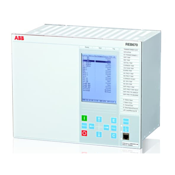
Section 5 1MRK 505 370-UUS A Local HMI Section 5 Local HMI AMU0600442 v14 ANSI13000239-2-en.vsd ANSI13000239 V2 EN-US Figure 33: Local human-machine interface The LHMI of the IED contains the following elements: Busbar protection REB670 2.2 ANSI Application manual... -
Page 104: Display
GUID-55739D4F-1DA5-4112-B5C7-217AAF360EA5 v11 The LHMI includes a graphical monochrome liquid crystal display (LCD) with a resolution of 320 x 240 pixels. The character size can vary. The display view is divided into four basic areas. Busbar protection REB670 2.2 ANSI Application manual... - Page 105 Each function button has a LED indication that can be used as a feedback signal for the function button control action. The LED is connected to the required signal with PCM600. Busbar protection REB670 2.2 ANSI Application manual...
- Page 106 Multipage button. Pressing the ESC button clears the panel from the display. Both panels have a dynamic width that depends on the label string length. Busbar protection REB670 2.2 ANSI Application manual...
-
Page 107: Leds
These LEDs can indicate the status of two arbitrary binary signals by configuring the OPENCLOSE_LED function block. For instance, OPENCLOSE_LED can be connected to a circuit breaker to indicate the breaker open/close status on the LEDs. Busbar protection REB670 2.2 ANSI Application manual... -
Page 108: Keypad
The push-buttons are also used to acknowledge alarms, reset indications, provide help and switch between local and remote control mode. The keypad also contains programmable push-buttons that can be configured either as menu shortcut or control buttons. Busbar protection REB670 2.2 ANSI Application manual... - Page 109 Figure 38: LHMI keypad with object control, navigation and command push- buttons and RJ-45 communication port 1...5 Function button Close Open Escape Left Down Right Enter Remote/Local Uplink LED Not in use Multipage Busbar protection REB670 2.2 ANSI Application manual...
-
Page 110: Local Hmi Functionality
The blocking of functions through the IEC61850 protocol can be reset in Main menu/Test/Reset IEC61850 Mod. The yellow LED changes to either On or Off state depending on the state of operation. Busbar protection REB670 2.2 ANSI Application manual... -
Page 111: Parameter Management
5.4.2 Parameter management GUID-5EE466E3-932B-4311-9FE1-76ECD8D6E245 v9 The LHMI is used to access the relay parameters. Three types of parameters can be read and written. • Numerical values • String values • Enumerated values Busbar protection REB670 2.2 ANSI Application manual... -
Page 112: Front Communication
Do not connect the IED front port to a LAN. Connect only a single local PC with PCM600 to the front port. It is only intended for temporary use, such as commissioning and testing. Busbar protection REB670 2.2 ANSI Application manual... -
Page 113: Section 6 Differential Protection
BTCZPDIF check zone protection function 3Id/I SYMBOL-JJ V1 EN-US Busbar protection 2Z-3Ph-4/8CT, BUTPTRC_Bx bay function (1≤x≤4 or 1≤x≤8) 3Id/I SYMBOL-JJ V1 EN-US Busbar protection 2Z-3Ph-4/8CT, BZITGGIO zone interconnection function 3Id/I SYMBOL-JJ V1 EN-US Busbar protection REB670 2.2 ANSI Application manual... - Page 114 Id/I IEC16000110 V1 EN-US Busbar protection 6Z-1Ph-24CT, BFPTRC_Fx feeder bay function (1≤ x ≤24) Id/I IEC16000110 V1 EN-US Busbar protection 6Z-1Ph-24CT, BICPTRC_x bus interconnector bay function (1≤ x ≤5) Id/I IEC16000110 V1 EN-US Busbar protection REB670 2.2 ANSI Application manual...
-
Page 115: Basic Applications
General M12097-3 v3 Basic types of applications for REB670 IED are shown and described in this chapter. For these applications usually three phase version of the IED, with two differential zones and four (or even eight) 3-phase CT inputs, is used. -
Page 116: General
Must be able to selectively detect faults and trip only the faulty part of the busbar system. Must be secure against maloperation due to auxiliary contact failure, possible human mistakes and faults in the secondary circuits and so on. Busbar protection REB670 2.2 ANSI Application manual... -
Page 117: Differential Protection
The analog generation of the busbar differential IEDs ( KA2, 87B, RADHA, RADSS, REB 103) generally solves all these problems caused by the CT non-linear characteristics by using the galvanic connection between the secondary circuits of all Busbar protection REB670 2.2 ANSI Application manual... - Page 118 IED, the IED algorithm would be quite complex. Thus, it was decided to re-use the ABB excellent experience from the analog percentage restrained differential protection IED (that is, RADSS and REB 103), and use only the...
- Page 119 RMS value of the incoming current into the differential protection zone RMS value of the differential current from the differential protection zone s = 0.53 operating slope for the differential function (fixed in the algorithm). Busbar protection REB670 2.2 ANSI Application manual...
-
Page 120: Check Zone Protection
CT cores are required, but also a need for extra cabling and a separate check zone differential relay. In REB670, an internal built-in check zone in the IED is provided, therefore there is no need for such costly external check zone. This is possible, mainly due to the following facts: •... - Page 121 And the check zone supervises differential protection zones. Exactly which differential protection zones shall be supervised by the operation of the check zone also varies, depending on the version of the IED used: Busbar protection REB670 2.2 ANSI Application manual...
-
Page 122: Switch Status Monitoring
Traditionally, the CT switching has been done in CT secondary circuits. However, with REB670 this is not the case. All necessary zone selection (that is, CT switching) is done in software. Therefore, the CT secondary circuits are always intact and without any auxiliary relay contacts. - Page 123 As the name of the scheme suggests, only when the auxiliary contacts signal clean “open” or clean “closed” position, disconnector is considered to be open respectively closed. However this poses the stringent requirements on the auxiliary contacts that the Busbar protection REB670 2.2 ANSI Application manual...
- Page 124 Table and the following two figures summarize the properties of these two schemes. Table 13: Treatment of primary object auxiliary contact status within BBP in REB670 Primary equipment Status in busbar protection Alarm facility...
- Page 125 The line disconnector position from a feeder bay might be required for busbar protection under certain circumstances. Typical example is when the line disconnector 989 and associated grounding switch QC1 are located between CT and protected busbar as indicated in Figure 45. Busbar protection REB670 2.2 ANSI Application manual...
-
Page 126: Ct Connection Control
In general, there are dedicated binary inputs available for one CT at each bay, to control its current connection towards differential zones, based on operational status of Busbar protection REB670 2.2 ANSI Application manual... - Page 127 B when input signal CTRLZB on corresponding bay block is given logical value zero. This setting is typically used for feeder bays in double busbar stations in order to form proper busbar disconnector replica. It is especially suitable both when normally open Busbar protection REB670 2.2 ANSI Application manual...
-
Page 128: Ct Disconnection For Bus Interconnector Ct Cores
First solution is with two sets of main CTs, which are located on both sides of the circuit breaker, as shown in Figure 46. en01000013_ansi.vsd ANSI01000013 V1 EN-US Figure 46: Example of station with two sets of main CTs in the bus-section bay Busbar protection REB670 2.2 ANSI Application manual... - Page 129 Thus, there is no zone overlapping across the section/coupler circuit breaker as shown in Figure 46. A blind spot exists between the current transformer and the circuit breaker in the bus section or bus-coupler bay as shown in Figure 47. Busbar protection REB670 2.2 ANSI Application manual...
- Page 130 It directly follows the philosophy used for RADSS/REB 103 schemes used for similar applications before. Principle connection between the bus-coupler CB normally closed auxiliary contact (“b” contact), REB670 and internal configuration logic, as shown in Figure 48.
- Page 131 With GIS or live tank circuit breakers, owing to high cost of HV CT installations, sometimes no current transformers are available in bus-section or bus-coupler bay. This is the third solution shown in Figure Busbar protection REB670 2.2 ANSI Application manual...
- Page 132 However some additional configuration logic is required to obtain automatic zone interconnection activation when bus coupler breaker shall be closed. Example of such logic, is shown in Figure for a two-zone differential protection application. Busbar protection REB670 2.2 ANSI Application manual...
-
Page 133: End Fault Protection
CB in a feeder bay. Therefore, it is directly related to the position of the main CT in feeder bay. Three CT positions in feeder bays are typically used in power systems around the world, as shown in Figure 51. Busbar protection REB670 2.2 ANSI Application manual... - Page 134 For better understanding end fault protection applications within busbar protection, the Figure is provided. Busbar protection REB670 2.2 ANSI Application manual...
- Page 135 (that is, remote ends zone 2 distance protection). However, the overall busbar protection behavior can be improved for primary faults within end fault regions, when feeder breaker is open. Under such circumstances the following actions can be taken: Busbar protection REB670 2.2 ANSI Application manual...
-
Page 136: Zone Interconnection (Load Transfer)
The switchgear interlocking system shall allow this only when the bus coupler breaker is already closed. Depending on the thermal capacity of the feeder busbar disconnectors (189 and 289) the opening of the bus coupler circuit breaker is Busbar protection REB670 2.2 ANSI Application manual... - Page 137 In two-zone busbar differential protections, it is determined by the end user with a settable setting ZoneSwitching. This parameter, for every bay, can be set to only one of the following three alternatives Busbar protection REB670 2.2 ANSI Application manual...
-
Page 138: Tripping Arrangements
The internal zone selection logic provides individual bay trip signals in the internal software and no external relay for this purpose are required. This arrangement insures correct trip signal distribution to all circuit breakers in case of Busbar protection REB670 2.2 ANSI Application manual... - Page 139 Note that in this case the external trip signal from other two IEDs shall be arranged via pulse timer in configuration in order to avoid locking of the trip signal between three IED. Such arrangement via GOOSE is given in Figure 53: Busbar protection REB670 2.2 ANSI Application manual...
- Page 140 A suitable external trip unit consists of a combination of RXMS1/RXMH 2 alternatively AR/MG6 when heavy duty contacts are required and only RXMS 1/AR relays when medium duty contacts are sufficient. Busbar protection REB670 2.2 ANSI Application manual...
-
Page 141: Mechanical Lock-Out Function
This can particularly occur during site testing. In this case it is recommended to use COMBIFLEX RXMH 2 or RXMVB 2 or MG6 heavy duty relays. 6.1.3.12 Trip circuit supervision M12121-3 v3 Busbar protection REB670 2.2 ANSI Application manual... -
Page 142: Two-Zone Busbar Arrangements
Example of single busbar section with six feeder bays This type of busbar arrangement can be very easily protected. The most common setups for this type of station are described in the following table. Busbar protection REB670 2.2 ANSI Application manual... -
Page 143: Single Busbar Arrangements With Sectionalizer
1Ph; 2-zones, 12-bays BBP (B20) 1Ph; 2-zones, 12-bays BBP (B21) 1Ph; 2-zones, 24-bays BBP (B31) Please note that the above Table is given for the preconfigured versions of REB670 which do not contain any VT inputs. 6.1.4.3 Single busbar arrangements with sectionalizer M6642-3 v5 This arrangement is very similar to the single busbar arrangement. -
Page 144: Single Busbar Arrangements With Bus-Section Breaker
1Ph; 2-zones, 24-bays BBP (B31) Please note that Table is given for the preconfigured versions of REB670 which do not contain any VT inputs. Two differential zones are available in the IED and the connecting of the two zones is simply controlled via zone interconnection logic, as described in Section "Zone... -
Page 145: H-Type Busbar Arrangements
CT input from bus-section bay Please note that Table is given for the preconfigured versions of REB670 which do not contain any VT inputs. For station with just one CT in the bus-section bay, it might be required, depending on the client requirements, to provide the special scheme for disconnection of bus-section CT when the bus-section CB is open. - Page 146 Some utilities prefer to have two differential zones, one for each bus section. The most common setups for this type of station are given in the following table. Busbar protection REB670 2.2 ANSI Application manual...
-
Page 147: Double Circuit Breaker Busbar Arrangement
1Ph; 2-zones, 24-bays BBP (B31) Please note that Table is given for the preconfigured versions of REB670 which do not contain any VT inputs. For station with double zone protection and just one set of CTs in the bus-section bay, it might be required, depending on the client requirements, to provide the special scheme for disconnection of bus-section CT when the bus-section CB is open. - Page 148 Please note that Table is given for the preconfigured versions of REB670 which do not contain any VT inputs. A principle overall drawing of how to use REB670 for this type of station is given in Figure 59. Busbar protection REB670 2.2 ANSI...
-
Page 149: Breaker-And-A-Half Busbar Arrangements
Feeder bay in double bus – double breaker station 6.1.4.7 Breaker-and-a-half busbar arrangements M6646-3 v5 A fewer number of circuit breakers are needed for the same flexibility as for double circuit breaker busbar arrangement, as shown in Figure 60. Busbar protection REB670 2.2 ANSI Application manual... - Page 150 1Ph; 2-zones, 12-bays BBP (B20) 6/12 1Ph; 2-zones, 12-bays BBP (B21) 6/12 1Ph; 2-zones, 24-bays BBP (B31) 12/24 Please note that Table is given for the preconfigured versions of REB670 which do not contain any VT inputs. Busbar protection REB670 2.2 ANSI Application manual...
-
Page 151: Double Busbar Single Breaker Arrangement
Section 6 1MRK 505 370-UUS A Differential protection A principle overall drawing of how to use REB670 for breaker-and-a-half station including internal CBF protection for middle breaker is given in Figure 61. REB 670 Remote Inter- Bxxx Trip Zone A... - Page 152 1Ph; 2-zones, 24-bays BBP (B31) *) with just one CT input from bus-coupler bay Please note that Table is given for the preconfigured versions of REB670 which do not contain any VT inputs. Busbar protection REB670 2.2 ANSI Application manual...
- Page 153 CT when the bus-coupler CB is open. For more info please refer to Figure 48. Some principle overall drawings of how to use REB670 in this type of station are given in Figure to Figure 67.
- Page 154 OC Trip CONNZB TRZONE CT Input TRBAY I3PB1 Other Equipment BBP & BFP trip command to feeder breaker Feeder Bay ANSI06000152_2_en.vsd ANSI06000152 V2 EN-US Figure 64: Feeder bay where b aux. contacts are used Busbar protection REB670 2.2 ANSI Application manual...
- Page 155 TRBAY I3PB1 Parameter ZoneSel must Other be set to "FixedToZB" Equipment BBP & BFP trip command to Bus-Coupler breaker en06000153_ansi.vsd ANSI06000153 V1 EN-US Figure 65: Bus coupler bay with two sets of CTs Busbar protection REB670 2.2 ANSI Application manual...
- Page 156 CT Input set to "FixedToZA&-ZB" tZeroCurrent=150ms Other Equipment BBP & BFP trip command to Bus-Coupler breaker en06000154_ansi.vsd ANSI06000154 V1 EN-US Figure 66: Bus coupler bay with one CT and a&b aux. contact from CB Busbar protection REB670 2.2 ANSI Application manual...
-
Page 157: Double Busbar Arrangements With Two Bus-Section Breakers And Two Bus-Coupler Breakers
189 289 189 289 189 289 189 289 189 189 289 189 289 189 289 189 289 xx06000016_ansi.vsd ANSI06000016 V1 EN-US Figure 68: Example of typical GIS station layout Busbar protection REB670 2.2 ANSI Application manual... -
Page 158: Combined Busbar Arrangements
Section 6 1MRK 505 370-UUS A Differential protection With REB670 this type of arrangement can be protected as described in the following table. Table 21: Possible solutions for a typical GIS station Version of REB670 IED Number of feeders on... - Page 159 Combination between double breaker and double busbar station layouts In this type of arrangement the double breaker bay has in the same time the role of the bus-coupler bay for normal double busbar single breaker stations. Therefore, zone Busbar protection REB670 2.2 ANSI Application manual...
- Page 160 1Ph; 2-zones, 12-bays BBP (B20) 1Ph; 2-zones, 12-bays BBP (B21) 1Ph; 2-zones, 24-bays BBP (B31) 3/18 Please note that Table is given for the preconfigured versions of REB670 which do not contain any VT inputs. Busbar protection REB670 2.2 ANSI Application manual...
-
Page 161: Six-Zone Busbar Arrangements
6.1.5.2 Typical arrangement which can be covered GUID-2BC52A24-7844-4F83-A11E-944FC3487582 v1 The six-zone busbar differential protection is intended for applications with complex switchgear layout. In general, there are the following restrictions: Busbar protection REB670 2.2 ANSI Application manual... - Page 162 Double busbar station with six protection zones Sectionalizing disconnectors QB11 QB21 QB10 QB20 Feeder 01-06 Bus-Interconnector 1 with two CTs Feeder 07-18 IEC16000143-1.en.vsdx IEC16000143 V1 EN-US Figure 73: Double busbar station with breaker bypass facility and four protection zones Busbar protection REB670 2.2 ANSI Application manual...
-
Page 163: Example Engineering Procedure
Example engineering procedure GUID-8E5A800E-F88D-4C93-B837-78D257774D3B v1 The procedure for how to engineer the triple busbar station with two sections and six protection zones (see Figure 75) will be presented here. Step 1: Allocation of protection zones Busbar protection REB670 2.2 ANSI Application manual... - Page 164 BBP including BFP tripping. ACT configuration example for Feeder 01 located at Section 1 is given in Figure 77. Any other feeders located at Section 1 shall be engineered in the similar way. Busbar protection REB670 2.2 ANSI Application manual...
- Page 165 The bus-coupler bay is used to interconnect the differential zones via a circuit breaker within one section. In this particular station, the Bus-Coupler 01 is located at Section 1 and consequently it can be connected to either Z1 or Z2 or Z3. How it is connected Busbar protection REB670 2.2 ANSI Application manual...
- Page 166 79. Any other bus coupler bays located at Section 1 shall be engineered in the similar way. For the bus coupler bays located at Section 2, similar steps to Step 3 shall be done, except the relevant zones are then Z4, Z5 and Z6. Busbar protection REB670 2.2 ANSI Application manual...
- Page 167 BICPTRC_xx function block. Ensure overlapping of the two CTs. In case that only one CT is available, connect this CT to both CT inputs on the BICPTRC_xx function block and then invert one of the two in the software by using the Busbar protection REB670 2.2 ANSI Application manual...
- Page 168 Z1&Z4, Z2&Z5 and Z3&Z6. When any linking shall occur, it depends on the operational status of the three bus-sectionalizing disconnectors. More specifically, the following steps need to be done: Busbar protection REB670 2.2 ANSI Application manual...
-
Page 169: Summation Principle
By using this approach, more cost effective bus differential protection can be obtained. Such a solution makes it feasible to apply bus differential protection even to medium voltage substations. The Busbar protection REB670 2.2 ANSI Application manual... - Page 170 Difference between phase segregated & summation type differential protection In the full phase-segregated design, three one-phase REB670 IEDs (that is, one per phase) are used. However for the summation type only single one-phase REB670 IED plus one auxiliary summation CT per each main CT is required. These auxiliary summation CTs convert each main CT three-phase currents to a single-phase output current, which are all measured by one REB670 IED.
- Page 171 CT shall not saturate quicker than 2 ms ( refer to section "Rated equivalent secondary e.m.f. requirements" for detailed CT requirements regarding main CT knee-point voltage) However, due to the summation principle this type of busbar protection scheme has the following limitations: Busbar protection REB670 2.2 ANSI Application manual...
-
Page 172: Auxiliary Summation Cts
The ASCT has three primary windings and one secondary winding. In further text, turn numbers of these windings will be marked with N1, N2, N3 & N4, respectively (see Figure for more information). There are three types of ASCT for REB670: Busbar protection REB670 2.2 ANSI Application manual... - Page 173 Burden is the total 3Ph load of ASCT imposed to the main CT Due to ASCT design, the ASCTs for summated bus differential protection, must always be mounted as close as possible to the IED (that is, in the same protection cubicle). Busbar protection REB670 2.2 ANSI Application manual...
-
Page 174: Possible Asct Connections For Reb670
Section 6 1MRK 505 370-UUS A Differential protection 6.1.6.3 Possible ASCT connections for REB670 M12137-3 v4 It is possible to connect the ASCTs for summated bus differential protection with REB670: • at the end of the main CT circuit (for example, beyond the other protective relays, as shown in Figure •... -
Page 175: Main Ct Ratio Mismatch Correction
The entered value, for the minimal differential operating current level, will exactly correspond to the REB670 pickup value in the event of a 3-phase internal fault. For all Busbar protection REB670 2.2 ANSI... - Page 176 In addition to busbar protection differential zones, the IED can incorporate other additional functions and features. If and how they can be used together with summation busbar protection design is shown in Table 25: Busbar protection REB670 2.2 ANSI Application manual...
- Page 177 CCRBRF/CCSRBRF and OC4PTOC/PHS4PTOC protections operation. DRPRDRE function Event List feature in the IED can be used in the exactly the same way as with phase segregated design. Table continues on next page Busbar protection REB670 2.2 ANSI Application manual...
-
Page 178: Slce 8/Asct Characteristics For End-Connection
IA N IA IB IA IB SUMM (Equation 12) EQUATION1785-ANSI V1 EN-US The relationships between number of turns for this SLCE 8, ASCT for REB670, is shown in Equation 13, Equation and Equation 15: (Equation 13) EQUATION1108 V1 EN-US ×... -
Page 179: Slce 8/Asct Characteristics For Series-Connection
N IA IB IC × SUMM (Equation 18) EQUATION1787-ANSI V1 EN-US The relationships between the number of turns for this SLCE 8 ASCT for REB670, is shown in Equation 19, Equation 20, Equation 21: (Equation 19) EQUATION1108 V1 EN-US ×... - Page 180 For any unbalanced condition (that is, external or internal fault), both negative and zero sequence current components will give their own contribution to the summated current. Busbar protection REB670 2.2 ANSI Application manual...
-
Page 181: Section 7 Current Protection
This is mostly the case when no fault current can be fed from the protected object itself. In order to achieve both selectivity and fast fault clearance, the directional function can be necessary. Busbar protection REB670 2.2 ANSI Application manual... - Page 182 If set 1 of 3 it is sufficient to have high current in one phase only. If set 2 of 3 or 3 of 3 single-phase ground faults are not detected. Busbar protection REB670 2.2 ANSI Application manual...
-
Page 183: Setting Guidelines
7% of IB. 2ndHarmStab: Operate level of 2nd harmonic current restrain set in % of the fundamental current. The setting range is 5 - 100% in steps of 1%. The default setting is 20%. Busbar protection REB670 2.2 ANSI Application manual... -
Page 184: Settings For Each Step
2. ROA = Relay operating angle 3. Reverse 4. Forward 7.1.3.1 Settings for each step M12982-19 v10 x means step 1, 2, 3 and 4. DirModeSelx: The directional mode of step x. Possible settings are Disabled/Non- directional/Forward/Reverse. Busbar protection REB670 2.2 ANSI Application manual... - Page 185 TDx: Time multiplier for inverse time delay for step x. IMinx: Minimum operate current in % of IB for all inverse time characteristics, below which no operation takes place. Busbar protection REB670 2.2 ANSI Application manual...
- Page 186 Note that the operate time is dependent on the selected time multiplier setting kx. ResetTypeCrvx: The reset of the delay timer can be made as shown in Table 27. Busbar protection REB670 2.2 ANSI Application manual...
- Page 187 HarmRestrainx: Enables the block of step x from the harmonic restrain function (2nd harmonic). This function should be used when there is a risk of an unwanted trip caused by power transformer inrush currents. It can be set to Disabled/Enabled. Busbar protection REB670 2.2 ANSI Application manual...
-
Page 188: Setting Example
Reset current The IED does not reset Time t ANSI09000146-en-1.vsd ANSI09000146 V1 EN-US Figure 89: Pickup and reset current for an overcurrent protection The lowest setting value can be written according to Equation 25. Busbar protection REB670 2.2 ANSI Application manual... - Page 189 It is desirable to have rapid tripping of faults within a large part of the power system to be protected by the protection (primary Busbar protection REB670 2.2 ANSI Application manual...
- Page 190 The time setting is chosen to get the shortest fault time with maintained selectivity. Selectivity is assured if the time difference between the curves is larger than a critical time difference. Busbar protection REB670 2.2 ANSI Application manual...
- Page 191 These time delays can vary significantly between different protective equipment. The following time delays can be estimated: Protection operation 15-60 ms time: Protection resetting time: 15-60 ms Breaker opening time: 20-120 ms Busbar protection REB670 2.2 ANSI Application manual...
- Page 192 There are uncertainties in the values of protection operation time, breaker opening time and protection resetting time. Therefore a safety margin has to be included. With normal values the needed time difference can be calculated according to Equation 29. Busbar protection REB670 2.2 ANSI Application manual...
-
Page 193: Four Step Single Phase Overcurrent Protection Ph4Sptoc (51)
• Back-up short circuit protection of power generators. The single phase overcurrent protection is used in IEDs having only input from one phase, for example busbar protection for large busbars (with many bays). Busbar protection REB670 2.2 ANSI Application manual... -
Page 194: Setting Guidelines
IED start time into consideration. The parameters for the four step phase overcurrent protection function (OC) are set via the local HMI or Protection and Control IED Manager (PCM 600). Busbar protection REB670 2.2 ANSI Application manual... -
Page 195: Settings For Each Step (X = 1-4)
IEC Very Inverse IEC Inverse IEC Extremely Inverse IEC Short Time Inverse IEC Long Time Inverse IEC Definite Time User Programmable ASEA RI RXIDG (logarithmic) The different characteristics are described in the “Technical reference manual”. Busbar protection REB670 2.2 ANSI Application manual... - Page 196 (1), IEC (2 = set constant time reset) and ANSI (3 = current dependent reset time). If the current dependent type is used then settings pr, tr and cr must be given. Busbar protection REB670 2.2 ANSI Application manual...
-
Page 197: Second Harmonic Restrain
A general description is given below. The pick up current setting inverse time protection or the lowest current step constant inverse time protection must be given a current setting so that the highest possible load Busbar protection REB670 2.2 ANSI Application manual... - Page 198 The current setting must be valid also for some years ahead. It is, in most cases, realistic that the setting values are Busbar protection REB670 2.2 ANSI Application manual...
- Page 199 Considerations have to be made to the risk of transient overreach, due to a possible DC component of the short circuit current. The lowest current setting of the most rapid stage, of the phase overcurrent protection, can be written according to Busbar protection REB670 2.2 ANSI Application manual...
- Page 200 The time setting is chosen to get the shortest fault time with maintained selectivity. Selectivity is assured if the time difference between the curves is larger than a critical time difference. Busbar protection REB670 2.2 ANSI Application manual...
- Page 201 These time delays can vary significantly between different pieces of equipment. The following time delays can be estimated: protection operation 15-60 ms time: protection resetting time: 15-60 ms Breaker opening time: 20-120 ms Busbar protection REB670 2.2 ANSI Application manual...
- Page 202 There are uncertainties in the values of protection operation time, breaker opening time and protection resetting time. Therefor a safety margin has to be included. With normal values the needed time difference can be calculated according to equation 35. Busbar protection REB670 2.2 ANSI Application manual...
-
Page 203: Directional Residual Overcurrent Protection, Four Steps Ef4Ptoc (51N/67N)
Common base IED values for primary current (IBase), primary voltage (UBase) and primary power (SBase) are set in the global base values for settings function GBASVAL. GlobalBaseSel: This is used to select GBASVAL function for reference of base values. Busbar protection REB670 2.2 ANSI Application manual... -
Page 204: Common Settings For All Steps
Relay characteristic angle given in degree In a normal transmission network a normal value of RCA is about 65°. The setting range is -180° to +180°. polMethod: Defines if the directional polarization is from Busbar protection REB670 2.2 ANSI Application manual... -
Page 205: 2Nd Harmonic Restrain
If a power transformer is energized there is a risk that the current transformer core will saturate during part of the period, resulting in a transformer inrush current. This will give a declining residual current in the network, as the inrush current is deviating Busbar protection REB670 2.2 ANSI Application manual... -
Page 206: Parallel Transformer Inrush Current Logic
Assume that step 4 is chosen to be the most sensitive step of the four step residual overcurrent protection function EF4PTOC (51N_67N). The harmonic restrain blocking is enabled for this step. Also the same current setting as this step is chosen for the blocking at parallel transformer energizing. Busbar protection REB670 2.2 ANSI Application manual... -
Page 207: Switch Onto Fault Logic
60.000 s in step of 0.001 s. The default setting is 0.100 s t4U: Time interval when the SOTF function is active after breaker closing. The setting range is 0.000 - 60.000 s in step of 0.001 s. The default setting is 1.000 s. Busbar protection REB670 2.2 ANSI Application manual... -
Page 208: Settings For Each Step (X = 1, 2, 3 And 4)
INx>, is used. The limits are used for decreasing the used range of the INx> setting. If INx> is set outside INx>Max and INx>Min, the closest of the limits to INx> is used by the function. If INx>Max is smaller than INx>Min, the limits are swapped. Busbar protection REB670 2.2 ANSI Application manual... - Page 209 ResetTypeCrvx: The reset of the delay timer can be made in different ways. The possibilities are described in the technical reference manual. tResetx: Constant reset time delay in s for step x. Busbar protection REB670 2.2 ANSI Application manual...
-
Page 210: Four Step Directional Negative Phase Sequence Overcurrent Protection Ns4Ptoc (46I2)
Four step negative sequence NS4PTOC 46I2 overcurrent protection IEC10000053 V1 EN-US 7.4.2 Application GUID-343023F8-AFE3-41C2-8440-1779DD7F5621 v2 Four step negative sequence overcurrent protection NS4PTOC (4612) is used in several applications in the power system. Some applications are: Busbar protection REB670 2.2 ANSI Application manual... - Page 211 IEC and ANSI. Table 30: Inverse time characteristics Curve name ANSI Extremely Inverse ANSI Very Inverse ANSI Normal Inverse ANSI Moderately Inverse ANSI/IEEE Definite time Table continues on next page Busbar protection REB670 2.2 ANSI Application manual...
-
Page 212: Setting Guidelines
Common base IED values for primary current (IBase), primary voltage (VBase) and primary power (SBase) are set in Global base values for settings function GBASVAL. GlobalBaseSel: It is used to select a GBASVAL function for reference of base values. Busbar protection REB670 2.2 ANSI Application manual... -
Page 213: Settings For Each Step
ANSI Long Time Very Inverse ANSI Long Time Inverse IEC Normal Inverse IEC Very Inverse IEC Inverse IEC Extremely Inverse IEC Short Time Inverse IEC Long Time Inverse IEC Definite Time User Programmable ASEA RI RXIDG (logarithmic) Busbar protection REB670 2.2 ANSI Application manual... - Page 214 Figure 98: Minimum operate current and operation time for inverse time characteristics ResetTypeCrvx: The reset of the delay timer can be made in different ways. By choosing setting there are the following possibilities: Busbar protection REB670 2.2 ANSI Application manual...
- Page 215 Further description can be found in the Technical reference manual (TRM). tPRCrvx, tTRCrvx, tCRCrvx: Parameters for customer creation of inverse reset time characteristic curve. Further description can be found in the Technical Reference Manual. Busbar protection REB670 2.2 ANSI Application manual...
-
Page 216: Common Settings For All Steps
I>Dir: Operate residual current level for directional comparison scheme. The setting is given in % of IBase. The pickup forward or pickup reverse signals can be used in a communication scheme. The appropriate signal must be configured to the communication scheme block. Busbar protection REB670 2.2 ANSI Application manual... -
Page 217: Thermal Overload Protection, Two Time Constants Trpttr (49)
The protection can have two sets of parameters, one for non-forced cooling and one for forced cooling. Both the permissive steady state loading level as well as the thermal Busbar protection REB670 2.2 ANSI Application manual... -
Page 218: Setting Guideline
In the standard for loading of a transformer an ambient temperature of 20°C is used. For lower ambient temperatures the load ability is increased and vice versa. IRefMult can be set within a range: 0.01 - 10.00. Busbar protection REB670 2.2 ANSI Application manual... - Page 219 The setting of the parameters below enables automatic adjustment of the time constant. Tau1High: Multiplication factor to adjust the time constant Tau1 if the current is higher than the set value IHighTau1. IHighTau1 is set in % of IBase1. Busbar protection REB670 2.2 ANSI Application manual...
- Page 220 ThetaInit: is set in % of the trip heat content level. Warning: If the calculated time to trip factor is below the setting Warning a warning signal is activated. The setting is given in minutes. Busbar protection REB670 2.2 ANSI Application manual...
-
Page 221: Breaker Failure Protection Ccrbrf(50Bf)
(50BF) are set via the local HMI or PCM600. The following settings can be done for the breaker failure protection. GlobalBaseSel: Selects the global base value group used by the function to define IBase, VBase and SBase as applicable. Operation: Disabled/Enabled Busbar protection REB670 2.2 ANSI Application manual... - Page 222 1 out of 4 means that at least one current of the three- phase currents or the residual current shall be high to indicate breaker failure. In most Busbar protection REB670 2.2 ANSI Application manual...
- Page 223 (the BFP_reset current criteria reset) is a safety margin margin Busbar protection REB670 2.2 ANSI Application manual...
- Page 224 The time delay for back-up trip is bypassed when the 52FAIL is active. Typical setting is 2.0 seconds. Busbar protection REB670 2.2 ANSI Application manual...
-
Page 225: Breaker Failure Protection, Single Phase Version Ccsrbrf (50Bf)
Setting guidelines SEMOD127980-4 v5 The parameters for Breaker failure protection, single phase version (CCSRBRF,50BF) are set via the local HMI or PCM600. The following settings can be done for the breaker failure protection. Busbar protection REB670 2.2 ANSI Application manual... - Page 226 Typical setting is 90 – 150 ms (also dependent of re-trip timer). The minimum time delay for the re-trip can be estimated as: ³ cbopen BFP reset margin (Equation 40) EQUATION1430 V1 EN-US Busbar protection REB670 2.2 ANSI Application manual...
- Page 227 This could be the case when gas pressure is low in a SF6 circuit breaker, of others. After the set time an alarm is given, so that actions can be done to repair the circuit Busbar protection REB670 2.2 ANSI Application manual...
-
Page 228: Directional Underpower Protection Guppdup (37)
In the last case, it is highly desirable to Busbar protection REB670 2.2 ANSI Application manual... - Page 229 3%. Diesel engines should have reverse power protection. The generator will take about 15% of its rated power or more from the system. A stiff engine may require perhaps Busbar protection REB670 2.2 ANSI Application manual...
-
Page 230: Setting Guidelines
IBase, VBase and SBase as applicable. Operation: With the parameter Operation the function can be set Enabled/Disabled. Mode: The voltage and current used for the power measurement. The setting possibilities are shown in table 33. Busbar protection REB670 2.2 ANSI Application manual... - Page 231 With the parameter OpMode1(2) the function can be set Enabled/Disabled. The function gives trip if the power component in the direction defined by the setting Angle1(2) is smaller than the set pick up power value Power1(2) Busbar protection REB670 2.2 ANSI Application manual...
- Page 232 The setting Angle1(2) gives the characteristic angle giving maximum sensitivity of the power protection function. The setting is given in degrees. For active power the set angle should be 0° or 180°. 0° should be used for generator low forward active power protection. Busbar protection REB670 2.2 ANSI Application manual...
- Page 233 Calculated is settable parameter Busbar protection REB670 2.2 ANSI Application manual...
-
Page 234: Directional Overpower Protection Goppdop (32)
If the generator under consideration is very large and if it consumes lots of electric power, it may be desirable to disconnect it to ease the task for the rest of the power system. Busbar protection REB670 2.2 ANSI Application manual... - Page 235 Ice and snow may block the intake when the outdoor temperature falls far below zero. Branches and leaves may also block the trash gates. A complete blockage of the intake Busbar protection REB670 2.2 ANSI Application manual...
-
Page 236: Setting Guidelines
Setting guidelines SEMOD172150-4 v7 GlobalBaseSel: Selects the global base value group used by the function to define IBase, VBase and SBase as applicable. Operation: With the parameter Operation the function can be set Enabled/Disabled. Busbar protection REB670 2.2 ANSI Application manual... - Page 237 With the parameter OpMode1(2) the function can be set Enabled/Disabled. The function gives trip if the power component in the direction defined by the setting Angle1(2) is larger than the set pick up power value Power1(2) Busbar protection REB670 2.2 ANSI Application manual...
- Page 238 The setting Angle1(2) gives the characteristic angle giving maximum sensitivity of the power protection function. The setting is given in degrees. For active power the set angle should be 0° or 180°. 180° should be used for generator reverse power protection. Busbar protection REB670 2.2 ANSI Application manual...
- Page 239 (Equation 65) EQUATION2047 V1 EN-US The drop out power will be Power1(2) - Hysteresis1(2). The possibility to have low pass filtering of the measured power can be made as shown in the formula: Busbar protection REB670 2.2 ANSI Application manual...
-
Page 240: Capacitor Bank Protection Cbpgapc
7.10 Capacitor bank protection CBPGAPC GUID-41731DCF-840C-4717-9F51-899FC648F881 v2 7.10.1 Identification GUID-67FC8DBF-4391-4562-A630-3F244CBB4A33 v2 Function description IEC 61850 IEC 60617 ANSI/IEEE C37.2 identification identification device number Capacitor bank protection CBPGAPC Busbar protection REB670 2.2 ANSI Application manual... -
Page 241: Application
Typically the neighboring capacitor units are mounted in racks. Each rack must be insulated from the other by insulators because the can casing within each rack are at a certain potential. Refer figure for an example: Busbar protection REB670 2.2 ANSI Application manual... - Page 242 SCB is built from series connections of the individual capacitor units (that is, strings) and without any fuses Unfused where, in contrary to the fuseless configuration, a series or parallel connection of the capacitor units is used to form SCB, still without any fuses Busbar protection REB670 2.2 ANSI Application manual...
-
Page 243: Scb Protection
HV live parts this can result in a flash-over, can rapture or a cascading failures that might cause extensive damages, fire or even total destruction of the whole SCB, unless the bank is sufficiently fitted with protection IEDs. Busbar protection REB670 2.2 ANSI Application manual... - Page 244 110% of the rated voltage on the remaining capacitors of that serial group. The value of 110% is the maximum continuous overvoltage capability of capacitor units as per IEEE Std 18-1992. The SCB typically requires the following types of IED protection: Busbar protection REB670 2.2 ANSI Application manual...
-
Page 245: Setting Guidelines
CBPGAPC 500/1 200MVAr 400kV IEC09000754-1-en.vsd IEC09000754 V1 EN-US Figure 109: Single line diagram for the application example From figure it is possible to calculate the following rated fundamental frequency current for this SCB: Busbar protection REB670 2.2 ANSI Application manual... - Page 246 PU 51 =135% (of IBase); Current level for overcurrent pickup. Selected value gives pickup recommended by international standards. tOC =30s; Time delay for overcurrent trip Undercurrent feature: Operation37 =Enabled; to enable this feature Busbar protection REB670 2.2 ANSI Application manual...
-
Page 247: Restrike Detection
7.10.3.1 Restrike detection GUID-114747A5-0F7C-4F48-A32D-0C13BFF6ADCE v1 Opening of SCBs can be quite problematic for certain types of circuit breakers (CBs). Typically such problems are manifested as CB restrikes. Busbar protection REB670 2.2 ANSI Application manual... - Page 248 CB behavior. Such CB condition can be just alarmed, and if required, the built in disturbance recorder can also be triggered. To create this logic, a binary signal that the CB is going to be opened (but not trip command) shall be made available to the IED. Busbar protection REB670 2.2 ANSI Application manual...
-
Page 249: Section 8 Voltage Protection
8.1.2.1 Equipment protection, such as for motors and generators M13851-50 v3 The setting must be below the lowest occurring "normal" voltage and above the lowest acceptable voltage for the equipment. Busbar protection REB670 2.2 ANSI Application manual... -
Page 250: Disconnected Equipment Detection
Characteristicn: This parameter gives the type of time delay to be used. The setting can be Definite time, Inverse Curve A, Inverse Curve B, Prog. inv. curve. The selection is dependent on the protection application. Busbar protection REB670 2.2 ANSI Application manual... - Page 251 For more information, see the Technical manual. IntBlkSeln: This parameter can be set to Disabled, Block of trip, Block all. In case of a low voltage the undervoltage function can be blocked. This function can be used to Busbar protection REB670 2.2 ANSI Application manual...
-
Page 252: Two Step Overvoltage Protection Ov2Ptov (59)
OV2PTOV (59) is used to disconnect apparatuses, like electric motors, which will be damaged when subject to service under high voltage conditions. It deals with high voltage conditions at power system frequency, which can be caused by: Busbar protection REB670 2.2 ANSI Application manual... -
Page 253: Setting Guidelines
Some applications and related setting guidelines for the voltage level are given below: The hysteresis is for overvoltage functions very important to prevent that a transient voltage over set level is not “sealed-in” due to a high hysteresis. Typical values should be ≤ 0.5%. Busbar protection REB670 2.2 ANSI Application manual... -
Page 254: Equipment Protection, Such As For Motors, Generators, Reactors And Transformers
VBase by √3. When ConnType is set to PhPh DFT or PhPh RMS then set value for VBase is used. Therefore, always set VBase as rated primary phase-to-phase ground voltage of the protected object. If phase to neutral (PhN) measurement is Busbar protection REB670 2.2 ANSI Application manual... - Page 255 For very high voltages the overvoltage function, using inverse time characteristic, can give very short operation time. This might lead to unselective trip. By setting t1Min longer than the operation time for other protections such unselective tripping can be avoided. Busbar protection REB670 2.2 ANSI Application manual...
-
Page 256: Two Step Residual Overvoltage Protection Rov2Ptov (59N)
Two step residual overvoltage protection ROV2PTOV (59N) IP14546-1 v4 8.3.1 Identification SEMOD54295-2 v6 Function description IEC 61850 IEC 60617 ANSI/IEEE C37.2 identification identification device number Two step residual overvoltage ROV2PTOV protection 2(U0>) IEC15000108 V1 EN-US Busbar protection REB670 2.2 ANSI Application manual... -
Page 257: Application
(ROV2PTOV, 59N) is connected. For selectivity reasons to the primary protection for the faulted device, ROV2PTOV (59N) must trip the component with some time delay. The setting must be above the highest Busbar protection REB670 2.2 ANSI Application manual... -
Page 258: Equipment Protection, Capacitors
The two healthy phases will measure full phase-to-phase voltage, as the faulty phase will be connected to ground. The residual overvoltage will be three times the phase-to-ground voltage. See figure 110. Busbar protection REB670 2.2 ANSI Application manual... -
Page 259: Direct Grounded System
The other healthy phase will still have normal phase-to-ground voltage. The residual sum will have the same value as the remaining phase-to-ground voltage, which is shown in Figure 111. ANSI07000189-1-en.vsd ANSI07000189 V1 EN-US Figure 111: Ground fault in Direct grounded system Busbar protection REB670 2.2 ANSI Application manual... -
Page 260: Settings For Two Step Residual Overvoltage Protection
100%. In effectively grounded systems, this value depends on the ratio Z0/Z1. The required setting to detect high resistive ground faults must be based on network calculations. Busbar protection REB670 2.2 ANSI Application manual... - Page 261 Make sure that the set value for parameter HystABSn is somewhat smaller than the set pickup value. Otherwise there is a risk that step n will not reset properly. Busbar protection REB670 2.2 ANSI Application manual...
-
Page 262: Voltage Differential Protection Vdcptov (60)
The function requires voltage transformers in all phases of the capacitor bank. Figure shows some different alternative connections of this function. Busbar protection REB670 2.2 ANSI Application manual... -
Page 263: Setting Guidelines
The parameters for the voltage differential function are set via the local HMI or PCM600. The following settings are done for the voltage differential function. Operation: Off/On GlobalBaseSel: Selects the global base value group used by the function to define IBase, VBase and SBase as applicable. Busbar protection REB670 2.2 ANSI Application manual... - Page 264 For fuse supervision normally only this alarm level is used and a suitable voltage level is 3-5% if the ratio correction factor has been properly evaluated during commissioning. Busbar protection REB670 2.2 ANSI Application manual...
-
Page 265: Loss Of Voltage Check Lovptuv (27)
(LOVPTUV, 27), if some but not all voltage are low, to typical 5.0 seconds and set the time delay for enabling the function after restoration tRestore to 3 - 40 seconds. Busbar protection REB670 2.2 ANSI Application manual... -
Page 267: Section 9 Frequency Protection
If the generator is still energized, the system will experience overexcitation, due to the low frequency. Busbar protection REB670 2.2 ANSI Application manual... -
Page 268: Setting Guidelines
The load shedding is then performed firstly in areas with low voltage magnitude, which normally are the most problematic areas, where the load shedding also is most efficient. Overfrequency protection SAPTOF (81) IP15747-1 v3 Busbar protection REB670 2.2 ANSI Application manual... -
Page 269: Identification
VBase. The UBase value should be set as a primary phase-to-phase value. Some applications and related setting guidelines for the frequency level are given below: Busbar protection REB670 2.2 ANSI Application manual... -
Page 270: Rate-Of-Change Of Frequency Protection Sapfrc (81)
In such situations load shedding actions are required at a rather high frequency level, but in combination with a large negative rate-of-change of frequency the underfrequency protection can be used at a rather high setting. Busbar protection REB670 2.2 ANSI Application manual... -
Page 271: Setting Guidelines
- up to 3 Hz/s has been experienced when a small island was isolated from a large system. For more "normal" severe disturbances in large power systems, rate-of-change of frequency is much less, most often just a fraction of 1.0 Hz/s. Busbar protection REB670 2.2 ANSI Application manual... -
Page 273: Section 10 Multipurpose Protection
Each CVGAPC function module has got four independent protection elements built into it. Two overcurrent steps with the following built-in features: Busbar protection REB670 2.2 ANSI Application manual... -
Page 274: Current And Voltage Selection For Cvgapc Function
(selected current quantity and selected voltage quantity). Busbar protection REB670 2.2 ANSI Application manual... - Page 275 Phase angle will be set to 0° all the time The user can select, by a setting parameter VoltageInput, to measure one of the following voltage quantities shown in table 36. Busbar protection REB670 2.2 ANSI Application manual...
- Page 276 It is important to notice that the voltage selection from table is always applicable regardless the actual external VT connections. The three-phase VT inputs can be connected to IED as either three phase-to-groundvoltages VA, VB and VC or three Busbar protection REB670 2.2 ANSI Application manual...
-
Page 277: Base Quantities For Cvgapc Function
Overcurrent protection (50, 51, 46, 67, 67N, 67Q) • Phase or phase-to-phase or Negative/Positive/Zero Sequence over/under voltage protection (27, 59, 47) • Special thermal overload protection (49) • Open Phase protection • Unbalance protection Generator protection Busbar protection REB670 2.2 ANSI Application manual... -
Page 278: Inadvertent Generator Energization
Of more critical concern, however, is the bearing, which can be damaged in a fraction of a second due to low oil pressure. Therefore, it is essential that high speed tripping is provided. This tripping should be almost instantaneous (< 100 ms). Busbar protection REB670 2.2 ANSI Application manual... -
Page 279: Setting Guidelines
Additionally, it can be used in applications on underground cables where zero-sequence impedance depends on the fault current return paths, but the cable negative-sequence impedance is Busbar protection REB670 2.2 ANSI Application manual... - Page 280 (10% is typical value) of measured PosSeq current in the power line. To do this the following settings within the same function shall be done: 16. Set EnRestrainCurr to On 17. Set RestrCurrInput to PosSeq 18. Set RestrCurrCoeff to value 0.1 Busbar protection REB670 2.2 ANSI Application manual...
-
Page 281: Negative Sequence Overcurrent Protection
20s, and maximum continuous negative sequence rating of 7% of the generator rated current. The capability curve for a generator negative sequence overcurrent protection, often used world-wide, is defined by the ANSI standard in accordance with the following formula: Busbar protection REB670 2.2 ANSI Application manual... - Page 282 Connect three-phase generator currents to one CVGAPC instance (for example, GF01) Set parameter CurrentInput to value NegSeq Set base current value to the rated generator current in primary amperes Enable one overcurrent step (for example, OC1) Select parameter CurveType_OC1 to value Programmable Busbar protection REB670 2.2 ANSI Application manual...
- Page 283 Furthermore the other built-in protection elements can be used for other protection and alarming purposes (for example, use OC2 for negative sequence overcurrent alarm and OV1 for negative sequence overvoltage alarm). Busbar protection REB670 2.2 ANSI Application manual...
-
Page 284: Generator Stator Overload Protection In Accordance With Iec Or Ansi Standards
3.5can be re-written in the following way without changing the value for the operate time of the generator stator overload IED: × æ ö ç ÷ × è ø (Equation 80) EQUATION1744-ANSI V1 EN-US Busbar protection REB670 2.2 ANSI Application manual... - Page 285 TD = 37.5 for the IEC standard or TD = 41.4 for the ANSI standard set A_OC1= 1/1.162 = 0.7432 set C_OC1= 1/1.162 = 0.7432 set B_OC1 = 0.0 and P_OC1 = 2.0 set PickupCurr_OC1 = 116% Busbar protection REB670 2.2 ANSI Application manual...
-
Page 286: Open Phase Protection For Transformer, Lines Or Generators And Circuit Breaker Head Flashover Protection For Generators
For example, in case of generator application by enabling OC2 step with set pickup to 200% and time delay to 0.1s simple but effective protection against circuit breaker head flashover protection is achieved. Busbar protection REB670 2.2 ANSI Application manual... -
Page 287: Voltage Restrained Overcurrent Protection For Generator And Step-Up Transformer
10.1.3.6 Loss of excitation protection for a generator M13088-182 v3 Example will be given how by using positive sequence directional overcurrent protection element within a CVGAPC function, loss of excitation protection for a Busbar protection REB670 2.2 ANSI Application manual... - Page 288 RCA & ROA angles will be applicable for OC2 step if directional feature is enabled for this step as well. Figure shows overall protection characteristic Furthermore the other build-in protection elements can be used for other protection and alarming purposes. Busbar protection REB670 2.2 ANSI Application manual...
- Page 289 Section 10 1MRK 505 370-UUS A Multipurpose protection Q [pu] Operating region ILowSet P [pu] -rca -0.2 -0.4 ILowSet Operating Region -0.6 -0.8 en05000535_ansi.vsd ANSI05000535 V1 EN-US Figure 113: Loss of excitation Busbar protection REB670 2.2 ANSI Application manual...
-
Page 291: Section 11 Secondary System Supervision
The negative sequence detection algorithm, based on the negative-sequence measuring quantities is recommended for use in isolated or high-impedance grounded networks: a Busbar protection REB670 2.2 ANSI Application manual... -
Page 292: Setting Guidelines
SealIn to Enabled since this will secure a fuse failure indication at persistent fuse fail when closing the local breaker when the line is already energized from the other end. When the remote breaker closes the voltage will return except in the phase that Busbar protection REB670 2.2 ANSI Application manual... -
Page 293: Negative Sequence Based
The setting of the current limit 3I2PU is in percentage of parameter IBase. The setting of 3I2PU must be higher than the normal unbalance current that might exist in the system and can be calculated according to equation 83. Busbar protection REB670 2.2 ANSI Application manual... -
Page 294: Zero Sequence Based
EQUATION2293-ANSI V2 EN-US where: 3I0PU is the maximal zero sequence current during normal operating conditions, plus a margin of 10...20% IBase GlobalBaseSel is the base current for the function according to the setting Busbar protection REB670 2.2 ANSI Application manual... -
Page 295: Delta V And Delta I
(mutual coupling to the other phases). Set the VDLDPU with a sufficient margin below the minimum expected operating voltage. A safety margin of at least 15% is recommended. 11.2 Fuse failure supervision VDSPVC (60) GUID-9C5BA1A7-DF2F-49D4-A13A-C6B483DDFCDC v2 Busbar protection REB670 2.2 ANSI Application manual... -
Page 296: Identification
VDSPVC output can be configured to block voltage dependent protection functions such as high-speed distance protection, undervoltage relays, underimpedance relays and so on. Busbar protection REB670 2.2 ANSI Application manual... -
Page 297: Setting Guidelines
The parameters for Fuse failure supervision VDSPVC are set via the local HMI or PCM600. GUID-0B298162-C939-47E4-A89B-7E6BD7BEBB2C v2 The voltage input type (phase-to-phase or phase-to-neutral) is selected using ConTypeMain and ConTypePilot parameters, for main and pilot fuse groups respectively. Busbar protection REB670 2.2 ANSI Application manual... - Page 298 When SealIn is set to On and the fuse failure has last for more than 5 seconds, the blocked protection functions will remain blocked until normal voltage conditions are restored above the VSealIn setting. The fuse failure outputs are deactivated when the normal voltage conditions are restored. Busbar protection REB670 2.2 ANSI Application manual...
-
Page 299: Section 12 Control
The synchronizing function measures the difference between the V-Line and the V- Bus. It operates and enables a closing command to the circuit breaker when the calculated closing angle is equal to the measured phase angle and the following conditions are simultaneously fulfilled: Busbar protection REB670 2.2 ANSI Application manual... - Page 300 CloseAngleMax = 30 degrees [max with (BusFrequency - [default value] value] LineFrequency) 0.040 0.080 1.000 0.050 0.100 0.800 0.080 0.160 0.500 0.200 0.400 0.200 0.400 0.810 0.100 1.000 0.080 0.800 0.050 1.000 0.040 Busbar protection REB670 2.2 ANSI Application manual...
-
Page 301: Synchronism Check
The synchronism check function measures the conditions across the circuit breaker and compares them to set limits. Output is generated only when all measured conditions are within their set limits simultaneously. The check consists of: Busbar protection REB670 2.2 ANSI Application manual... - Page 302 In this case it should be safer to close when the phase angle difference is smaller. To fulfill the above requirements the synchronism check function is provided with duplicate settings, one for steady (Manual) conditions and one for operation under disturbed conditions (Auto). Busbar protection REB670 2.2 ANSI Application manual...
-
Page 303: Energizing Check
CB B is energized (DLLB) from substation 1 via the circuit breaker A and energization of station 2 is done by CB B energization check device for that breaker DBLL. (or Both). Busbar protection REB670 2.2 ANSI Application manual... -
Page 304: Voltage Selection
The voltage selection function is used for the connection of appropriate voltages to the synchronism check, synchronizing and energizing check functions. For example, when the IED is used in a double bus arrangement, the voltage that should be selected Busbar protection REB670 2.2 ANSI Application manual... -
Page 305: External Fuse Failure
(B16I). If the PSTO input is used, connected to the Local-Remote switch on the local HMI, the choice can also be from the station HMI system, typically ABB Microscada through IEC 61850–8–1 communication. -
Page 306: Application Examples
The input used below in example are typical and can be changed by use of configuration and signal matrix tools. The SESRSYN and connected SMAI function block instances must have the same cycle time in the application configuration. Busbar protection REB670 2.2 ANSI Application manual... -
Page 307: Single Circuit Breaker With Single Busbar
The voltage from busbar VT is connected to V3PB1 and the voltage from the line VT is connected to V3PL1. The conditions of the VT fuses shall also be connected as shown above. The voltage selection parameter CBConfig is set to No voltage sel. Busbar protection REB670 2.2 ANSI Application manual... -
Page 308: Single Circuit Breaker With Double Busbar, External Voltage Selection
This means that the connections to the function block will be the same as for the single busbar arrangement. The voltage selection parameter CBConfig is set to No voltage sel. Busbar protection REB670 2.2 ANSI Application manual... -
Page 309: Single Circuit Breaker With Double Busbar, Internal Voltage Selection
V3PB1 and the voltage from busbar 2 is connected to V3PB2. The voltage from the line VT is connected to V3PL1. The positions of the disconnectors and VT fuses shall be connected as shown in figure 121. The voltage selection parameter CBConfig is set to Double bus. Busbar protection REB670 2.2 ANSI Application manual... -
Page 310: Double Circuit Breaker
TSTSYNCH FRDIFFM TSTSC PHDIFFM TSTENERG INADVCLS AENMODE VDIFFME MENMODE FRDIFFME PHDIFFME Vbus VLine MODEAEN MODEMEN ANSI10000096-1-en.vsd ANSI10000096 V1 EN-US Figure 122: Connections of the SESRSYN (25) function block in a double breaker arrangement Busbar protection REB670 2.2 ANSI Application manual... -
Page 311: Breaker-And-A-Half
VT is connected to V3PL2 on all three function blocks. The positions of the disconnectors and VT fuses shall be connected as shown in Figure 123. Busbar protection REB670 2.2 ANSI Application manual... - Page 312 INADVCLS AENMODE VDIFFME MENMODE FRDIFFME PHDIFFME Vbus VLine MODEAEN MODEMEN Tie CB ANSI10000097-1-en.vsd ANSI10000097 V1 EN-US Figure 123: Connections of the SESRSYN (25) function block in a breaker-and-a-half arrangement with internal voltage selection Busbar protection REB670 2.2 ANSI Application manual...
- Page 313 Setting CBConfig = 1 1/2 bus alt. CB If only two SESRSYN functions are provided in the same IED, the connections and settings are according to the SESRSYN functions for WA1_QA1 and TIE_QA1. Busbar protection REB670 2.2 ANSI Application manual...
-
Page 314: Setting Guidelines
2 respectively, which can be a single-phase (phase-neutral), two-phase (phase- phase) or a positive sequence voltage. CBConfig This configuration setting is used to define type of voltage selection. Type of voltage selection can be selected as: Busbar protection REB670 2.2 ANSI Application manual... - Page 315 For frequency differences lower than this value, the systems are considered to be in parallel. A typical value for FreqDiffMin is 10 mHz. Generally, the value should be low if both synchronizing and synchrocheck functions Busbar protection REB670 2.2 ANSI Application manual...
- Page 316 FreqDiffMin, which will decide how long it will take maximum to reach phase equality. At the setting of 10 mHz, the beat time is 100 seconds and the setting would thus need to be at least tMinSynch plus 100 seconds. If the network frequencies are Busbar protection REB670 2.2 ANSI Application manual...
- Page 317 A typical maximum value in heavy-loaded networks can be 45 degrees, whereas in most networks the maximum occurring angle is below 25 degrees. The PhaseDiffM setting is a limitation to Busbar protection REB670 2.2 ANSI Application manual...
- Page 318 The threshold voltages VLiveBusEnerg and VLiveLineEnerg have to be set lower than the value at which the network is considered to be energized. A typical value can be 80% of the base voltages. VDeadBusEnerg and VDeadLineEnerg Busbar protection REB670 2.2 ANSI Application manual...
-
Page 319: Autorecloser For 1 Phase, 2 Phase And/Or 3 Phase Operation Smbrrec (79)
IP14559-1 v6 12.2.1 Identification M14890-1 v7 Function Description IEC 61850 IEC 60617 ANSI/IEEE C37.2 identification identification device number Autorecloser for 1 phase, 2 phase and/or 3 SMBRREC phase 5(0 -->1) IEC15000204 V1 EN-US Busbar protection REB670 2.2 ANSI Application manual... -
Page 320: Application
Sensitive differential protection level available in REB670 can be used during such operation, if increased sensitivity from busbar protection is required. Such busbar restoration logic can be implemented by using optionally available auto reclosers and built-in logical gates. - Page 321 To maximize the availability of the power system it is possible to choose single-phase tripping and automatic reclosing during single-phase faults and three-phase tripping and automatic reclosing during multi-phase faults. Three-phase automatic reclosing can be performed with or without the use of synchrocheck. Busbar protection REB670 2.2 ANSI Application manual...
- Page 322 Single-shot and multi-shot are in use. The first shot can have a short delay, HSAR, or a longer delay, DAR. The second and following reclosing shots have a rather long delay. When multiple shots are used the dead time must harmonize with the breaker duty-cycle capacity. Busbar protection REB670 2.2 ANSI Application manual...
- Page 323 This provides a fail safe connection so that even a failure in the IED with the auto-recloser will mean that the other sub-system will start a three-pole trip. Busbar protection REB670 2.2 ANSI Application manual...
-
Page 324: Auto Reclosing Operation Off And On
A number of conditions need to be fulfilled for the start to be accepted and a new auto reclosing cycle to be started. They are linked to dedicated inputs. The inputs are: Busbar protection REB670 2.2 ANSI Application manual... -
Page 325: Initiate Auto Reclosing From Circuit Breaker Open Information
1Ph, t1 2Ph, t1 3Ph. If no particular input signal is applied, and an auto reclosing program with single-phase auto reclosing is selected, the auto reclosing dead time t1 1Ph will be used. If one of the TR2P or TR3P inputs is activated in connection with the Busbar protection REB670 2.2 ANSI Application manual... -
Page 326: Long Trip Signal
The auto reclosing is as a three-phase auto reclosing as in mode 1/2/3ph described below. All signals, blockings, inhibits, timers, requirements and so on, are the same as in the example described below. Busbar protection REB670 2.2 ANSI Application manual... -
Page 327: Armode = 1/2/3Ph
At two-pole trip, a failure of a two-pole auto reclosing attempt will inhibit the auto recloser. No more shots are attempted. If the first trip is a three- pole trip, the auto-reclosing will be inhibited. No more shots are attempted. The Busbar protection REB670 2.2 ANSI Application manual... -
Page 328: Armode = 1/2Ph + 1*3Ph, 1-Phase, 2-Phase Or 3-Phase Reclosing In The First Shot
Type of reclosing shots at different settings of ARMode or integer inputs to MODEINT MODEINT (integer) ARMode Type of fault 1st shot 2nd-5th shot 1/2/3ph 1/2ph ..1ph + 1*2ph ....1/2ph + 1*3ph ..Table continues on next page Busbar protection REB670 2.2 ANSI Application manual... -
Page 329: External Selection Of Auto Reclosing Mode
The circuit breaker closing command, CLOSECB is given as a pulse with a duration set by the tPulse setting. For circuit breakers without an anti-pumping function, close pulse cutting can be used. It is selected by the CutPulse setting. In case of a new start Busbar protection REB670 2.2 ANSI Application manual... -
Page 330: Transient Fault
IED, whether an external physical lock-out relay exists and whether the reset is hardwired, or carried out by means of communication. There are also Busbar protection REB670 2.2 ANSI Application manual... - Page 331 SMBRREC (79) BJ-TRIP INHIBIT ZCVPSOF-TRIP UNSUCCL SMBO ELECTRICAL RESET RELAY Lock-out RXMD1 CCRBRF (50BF) TRBU RESET CLOSE COMMAND MAIN ZAK CLOSE ANSI05000315_2_en.vsd ANSI05000315 V2 EN-US Figure 126: Lock-out arranged with an external lock-out relay Busbar protection REB670 2.2 ANSI Application manual...
-
Page 332: Evolving Fault
Automatic continuation of the auto reclosing sequence M12391-223 v5 The auto recloser can be programmed to proceed to the next auto reclosing shots (if multiple shots are selected) even if start signals are not received from protection Busbar protection REB670 2.2 ANSI Application manual... -
Page 333: Thermal Overload Protection Holding The Auto Recloser Back
(parallel connection of NC contacts). The CBREADY is a signal meaning that the circuit breaker is ready for an auto reclosing operation, either Close- Open (CO), or Open-Close-Open (OCO). If the available signal is of type “circuit Busbar protection REB670 2.2 ANSI Application manual... - Page 334 There is a counter for each type of auto reclosing and one for the total number of circuit breaker close commands issued. All counters are reset with the RSTCOUNT input or by an IEC 61850 command. Busbar protection REB670 2.2 ANSI Application manual...
- Page 335 Signal TR2P needs to be connected only if the trip function block has been selected to give 1/2/3 pole trip and an auto reclosing cycle with two phase reclosing is foreseen. Busbar protection REB670 2.2 ANSI Application manual...
- Page 336 • wait: an auto recloser, acting as slave, is waiting for a release from the master to proceed with its own reclosing sequence Busbar protection REB670 2.2 ANSI Application manual...
- Page 337 Prepare three-pole trip is usually connected to the trip block to force a coming trip to be a three-pole one. If the auto recloser cannot make a single-pole or two-pole auto reclosing, the tripping should be three-pole. Busbar protection REB670 2.2 ANSI Application manual...
- Page 338 Figure is showing an example of how to connect the auto recloser when used for single-pole, two-pole or three-pole auto reclosing. Busbar protection REB670 2.2 ANSI Application manual...
- Page 339 TRSOTF ZMQPDIS (21)--TRIP 3PT2 3PT3 THOLHOLD 3PT4 TR2P 3PT5 TRUE TR3P SESRSYN (25)-AUTOOK SYNC WAIT RSTCOUNT WFMASTER ANSI04000135-3-en.vsd ANSI04000135 V3 EN-US Figure 128: Example of I/O-signal connections at a three-phase auto reclosing sequence Busbar protection REB670 2.2 ANSI Application manual...
- Page 340 The reason for shortening the time, for the normal dead timers with the value of tSlaveDeadTime, is to give the slave permission to react almost immediately when the WAIT input resets. The mimimum settable time Busbar protection REB670 2.2 ANSI Application manual...
- Page 341 If the High priority circuit breaker is not closed the High priority moves to the low priority circuit breaker. Busbar protection REB670 2.2 ANSI Application manual...
-
Page 342: Auto Recloser Settings
This setting guideline describes the settings of the auto recloser using the LHMI. The settings for the auto recloser are found under Main menu/Settings/IED Settings/ Control/AutoRecloser(79,5(0->1))/SMBRREC(79,5(0->)):X and have been divided into four different setting groups: General, CircuitBreaker, DeadTime and MasterSlave. Busbar protection REB670 2.2 ANSI Application manual... - Page 343 To ensure reliable interruption and temporary blocking of the auto recloser a resetting time delay tInhibit is used. The auto recloser will be blocked this time after the deactivation of the INHIBIT input. A typical resetting delay is 5.0 s. Busbar protection REB670 2.2 ANSI Application manual...
- Page 344 The circuit breaker closing command should be long enough to ensure reliable operation of the circuit breaker. The circuit breaker closing command pulse has a duration set by the tPulse setting. A typical setting may be tPulse = 200 ms. A longer Busbar protection REB670 2.2 ANSI Application manual...
- Page 345 (shots) can be motivated. t1 1Ph, t1 2Ph, t1 3Ph: There are separate settings for the first shot for single-, two- and three-phase auto reclosing dead times. Busbar protection REB670 2.2 ANSI Application manual...
- Page 346 Typical setting is 2sec. tSlaveDeadTime: When activating the WAIT input, in the auto recloser set as slave, every dead timer is changed to the value of setting tSlaveDeadTime and holds back the Busbar protection REB670 2.2 ANSI Application manual...
-
Page 347: Apparatus Control Apc
The commands to an apparatus can be initiated from the Control Centre (CC), the station HMI or the local HMI on the IED front. Busbar protection REB670 2.2 ANSI Application manual... - Page 348 The apparatus control function is realized by means of a number of function blocks designated: • Switch controller SCSWI • Circuit breaker SXCBR • Circuit switch SXSWI • Bay control QCBAY • Bay reserve QCRSV Busbar protection REB670 2.2 ANSI Application manual...
- Page 349 GOOSE receive for switching device GOOSEXLNRCV • Proxy for signals from switching device via GOOSE XLNPROXY The extension of the signal flow and the usage of the GOOSE communication are shown in Figure 133. Busbar protection REB670 2.2 ANSI Application manual...
- Page 350 Control IEC 61850 QCBAY SXCBR SCSWI SXCBR SXCBR SCILO SCSWI SXSWI SCILO en05000116_ansi.vsd ANSI05000116 V1 EN-US Figure 132: Signal flow between apparatus control function blocks when all functions are situated within the IED Busbar protection REB670 2.2 ANSI Application manual...
- Page 351 GOOSE over process bus Merging Unit XCBR -QB1 XCBR XCBR -QA1 XSWI -QB9 IEC16000070-1-EN.vsdx IEC16000070 V1 EN-US Figure 133: Signal flow between apparatus control functions with XCBR and XSWI located in a breaker IED Busbar protection REB670 2.2 ANSI Application manual...
- Page 352 According to IEC 61850 standard the orCat attribute in originator category are defined Table 40 Table 40: orCat attribute according to IE C61850 Value Description not-supported bay-control station-control remote-control automatic-bay automatic-station automatic-remote maintenance process Busbar protection REB670 2.2 ANSI Application manual...
-
Page 353: Bay Control Qcbay
QCBAY also provides blocking functions that can be distributed to different apparatuses within the bay. There are two different blocking alternatives: • Blocking of update of positions • Blocking of commands IEC13000016-2-en.vsd IEC13000016 V2 EN-US Figure 134: APC - Local remote function block Busbar protection REB670 2.2 ANSI Application manual... -
Page 354: Switch Controller Scswi
The intention with these functions is to represent the lowest level of a power-switching device with or without short circuit breaking capability, for example, circuit breakers, disconnectors, grounding switches etc. Busbar protection REB670 2.2 ANSI Application manual... -
Page 355: Proxy For Signals From Switching Device Via Goose Xlnproxy
To make it easy to choose which data to use for the XLNPROXY function, their usage is controlled by the connection of each data’s signal input and valid input. These connections are usually from the GOOSEXLNRCV function (see Figure and Figure 136). Busbar protection REB670 2.2 ANSI Application manual... - Page 356 Section 12 1MRK 505 370-UUS A Control IEC16000071 V1 EN-US Figure 135: Configuration with XLNPROXY and GOOSEXLNRCV where all the IEC 61850 modelled data is used, including selection Busbar protection REB670 2.2 ANSI Application manual...
- Page 357 SCSWI function. This cause is also shown on the output L_CAUSE as indicated in the following table: Busbar protection REB670 2.2 ANSI Application manual...
-
Page 358: Reservation Function (Qcrsv And Resin)
To ensure that the interlocking information is correct at the time of operation, a unique reservation method is available in the IEDs. With this reservation method, the bay that Busbar protection REB670 2.2 ANSI Application manual... - Page 359 The reservation can also be realized with external wiring according to the application example in Figure 138. This solution is realized with external auxiliary relays and extra binary inputs and outputs in each IED, but without use of function blocks QCRSV and RESIN. Busbar protection REB670 2.2 ANSI Application manual...
-
Page 360: Interaction Between Modules
Application principle for an alternative reservation solution 12.3.2 Interaction between modules M16626-3 v8 A typical bay with apparatus control function consists of a combination of logical nodes or functions that are described here: Busbar protection REB670 2.2 ANSI Application manual... - Page 361 (energizing-check) is included. • The Generic Automatic Process Control function, GAPC, handles generic commands from the operator to the system. The overview of the interaction between these functions is shown in Figure below. Busbar protection REB670 2.2 ANSI Application manual...
- Page 362 Close rel. (Not a LN) (Interlocking) Position Enable Enable open close Res. GAPC Open cmd granted (Generic Close cmd Automatic SXSWI SCSWI Open/Close Process (Disconnector) (Switching control) Control) Open/Close Position IEC05000120-3-EN.vsdx IEC05000120 V3 EN-US Busbar protection REB670 2.2 ANSI Application manual...
- Page 363 Open cmd granted (Generic Close cmd Automatic SXSWI SCSWI Open/Close Process (Disconnector) (Switching control) Control) Open/Close Position ANSI05000120-2-en.vsd ANSI05000120 V2 EN-US Figure 140: Example overview of the interactions between functions in a typical Busbar protection REB670 2.2 ANSI Application manual...
-
Page 364: Setting Guidelines
When the time has expired, the selected output signal is set to false and a cause-code is given. Busbar protection REB670 2.2 ANSI Application manual... -
Page 365: Switch (Sxcbr/Sxswi)
SuppressMidPos is set to On in the SCSWI function. If the parameter AdaptivePulse is set to Adaptive the command output pulse resets when a new correct end position is reached. If the parameter is set to Not adaptive the Busbar protection REB670 2.2 ANSI Application manual... -
Page 366: Proxy For Signals From Switching Device Via Goose Xlnproxy
In most cases, the same value can be used for both tStartMove and tIntermediate as in the source function. However, tStartMove may need to be increased to accommodate for the communication delays, mainly when representing a circuit breaker. Busbar protection REB670 2.2 ANSI Application manual... -
Page 367: Bay Reserve (Qcrsv)
(for example, < 1% of rated voltage). Paralleling of power transformers is not allowed. Grounding switches are allowed to connect and disconnect grounding of isolated points. Due to capacitive or inductive coupling there may be some voltage (for Busbar protection REB670 2.2 ANSI Application manual... -
Page 368: Configuration Guidelines
They also describe the configuration settings. The inputs for delivery specific conditions (Qx_EXy) are set to 1=TRUE if they are not used, except in the following cases: • 989_EX2 and 989_EX4 in modules BH_LINE_A and BH_LINE_B • 152_EX3 in module AB_TRAFO Busbar protection REB670 2.2 ANSI Application manual... -
Page 369: Interlocking For Line Bay Abc_Line (3)
All line disconnectors on bypass WA7 except in the own bay are open. VP_BB7_D The switch status of disconnectors on bypass busbar WA7 are valid. EXDU_BPB No transmission error from any bay containing disconnectors on bypass busbar Busbar protection REB670 2.2 ANSI Application manual... -
Page 370: Signals From Bus-Coupler
Signals from bus-coupler M13560-31 v4 If the busbar is divided by bus-section disconnectors into bus sections, the busbar- busbar connection could exist via the bus-section disconnector and bus-coupler within the other bus section. Busbar protection REB670 2.2 ANSI Application manual... - Page 371 The switch status of BC_12 is valid. VPBC17TR The switch status of BC_17 is valid. VPBC27TR The switch status of BC_27 is valid. EXDU_BC No transmission error from the bay that contains the above information. Busbar protection REB670 2.2 ANSI Application manual...
- Page 372 VPS1S2TR The switch status of bus-section coupler BS is valid. EXDU_BS No transmission error from the bay that contains the above information. For a line bay in section 1, these conditions are valid: Busbar protection REB670 2.2 ANSI Application manual...
- Page 373 Signals to a line bay in section 1 from the bus-coupler bays in each section For a line bay in section 2, the same conditions as above are valid by changing section 1 to section 2 and vice versa. Busbar protection REB670 2.2 ANSI Application manual...
-
Page 374: Configuration Setting
0 and 1 are designated 0=FALSE and 1=TRUE: • 289_OP = 1 • 289_CL = 0 • 2189G_OP = 1 • 2189G_CL = 0 • BC_12_CL = 0 • BC_27_OP = 1 • BC_27_CL = 0 • VP_BC_12 = 1 Busbar protection REB670 2.2 ANSI Application manual... -
Page 375: Interlocking For Bus-Coupler Bay Abc_Bc (3)
No transmission error from any bay connected to the WA1/WA2 busbars. These signals from each line bay (ABC_LINE), each transformer bay (AB_TRAFO), and bus-coupler bay (ABC_BC), except the own bus-coupler bay are needed: Busbar protection REB670 2.2 ANSI Application manual... - Page 376 BBTR above, add this logic: Section 1 Section 2 (WA1)A1 (WA2)B1 (WA7)C A1A2_DC(BS) ABC_BC B1B2_DC(BS) ABC_LINE ABC_BC ABC_LINE AB_TRAFO en04000482_ansi.vsd ANSI04000482 V1 EN-US Figure 147: Busbars divided by bus-section disconnectors (circuit breakers) Busbar protection REB670 2.2 ANSI Application manual...
- Page 377 Signals to a bus-coupler bay in section 1 from any bays in each section For a bus-coupler bay in section 2, the same conditions as above are valid by changing section 1 to section 2 and vice versa. Busbar protection REB670 2.2 ANSI Application manual...
-
Page 378: Signals From Bus-Coupler
A1A2_DC and B1B2_DC. Signal DCCLTR The bus-section disconnector is closed. VPDCTR The switch status of bus-section disconnector DC is valid. EXDU_DC No transmission error from the bay that contains the above information. Busbar protection REB670 2.2 ANSI Application manual... -
Page 379: Configuration Setting
In the functional block diagram, 0 and 1 are designated 0=FALSE and 1=TRUE: • 289_OP = 1 • 289_CL = 0 • 789_OP = 1 • 789_CL = 0 Busbar protection REB670 2.2 ANSI Application manual... -
Page 380: Interlocking For Transformer Bay Ab_Trafo (3)
The function is used when there is no disconnector between circuit breaker and transformer. Otherwise, the interlocking for line bay (ABC_LINE, 3) function can be used. This function can also be used in single busbar arrangements. Busbar protection REB670 2.2 ANSI Application manual... -
Page 381: Signals From Bus-Coupler
12.4.4.2 Signals from bus-coupler M13566-6 v4 If the busbar is divided by bus-section disconnectors into bus-sections, the busbar- busbar connection could exist via the bus-section disconnector and bus-coupler within the other bus-section. Busbar protection REB670 2.2 ANSI Application manual... -
Page 382: Configuration Setting
In the functional block diagram, 0 and 1 are designated 0=FALSE and 1=TRUE: • 289_OP = 1 • 289QB2_CL = 0 • 2189G_OP = 1 • 2189G_CL = 0 • BC_12_CL = 0 • VP_BC_12 = 1 Busbar protection REB670 2.2 ANSI Application manual... -
Page 383: Interlocking For Bus-Section Breaker A1A2_Bs (3)
Busbar protection REB670 2.2 ANSI Application manual... - Page 384 WA2. VPBC12TR The switch status of BC_12 is valid. EXDU_BC No transmission error from the bay that contains the above information. These signals from the bus-section circuit breaker bay (A1A2_BS, B1B2_BS) are needed. Busbar protection REB670 2.2 ANSI Application manual...
- Page 385 EXDU_BC (sect.2) EXDU_12(bay 1/sect.1) ..EXDU_12 (bay n /sect.1) en04000490_ansi.vsd ANSI04000490 V1 EN-US Figure 155: Signals from any bays for a bus-section circuit breaker between sections A1 and A2 Busbar protection REB670 2.2 ANSI Application manual...
-
Page 386: Configuration Setting
152 open circuit breaker is not used or the state for BBTR is set to open. That is, no busbar transfer is in progress in this bus-section: • BBTR_OP = 1 • VP_BBTR = 1 Busbar protection REB670 2.2 ANSI Application manual... -
Page 387: Interlocking For Bus-Section Disconnector A1A2_Dc (3)
B are used. Section 1 Section 2 (WA1)A1 (WA2)B1 (WA7)C A1A2_DC(BS) B1B2_DC(BS) ABC_BC ABC_LINE AB_TRAFO ABC_LINE AB_TRAFO en04000493_ansi.vsd ANSI04000493 V1 EN-US Figure 158: Busbars divided by bus-section disconnectors (circuit breakers) To derive the signals: Busbar protection REB670 2.2 ANSI Application manual... - Page 388 289 is open. VP189TR The switch status of 189 is valid. VP289TR The switch status of 289 is valid. EXDU_BS No transmission error from the bay BS (bus-section coupler bay) that contains the above information. Busbar protection REB670 2.2 ANSI Application manual...
- Page 389 EXDU_BB (bay n/sect.A2) EXDU_DC (A2/A3) en04000495_ansi.vsd ANSI04000495 V1 EN-US Figure 160: Signals from any bays in section A2 to a bus-section disconnector For a bus-section disconnector, these conditions from the B1 busbar section are valid: Busbar protection REB670 2.2 ANSI Application manual...
-
Page 390: Signals In Double-Breaker Arrangement
Signals in double-breaker arrangement M13542-80 v5 If the busbar is divided by bus-section disconnectors, the condition for the busbar disconnector bay no other disconnector connected to the bus-section must be made by a project-specific logic. Busbar protection REB670 2.2 ANSI Application manual... - Page 391 No transmission error from the bay that contains the above information. The logic is identical to the double busbar configuration “Signals in single breaker arrangement”. For a bus-section disconnector, these conditions from the A1 busbar section are valid: Busbar protection REB670 2.2 ANSI Application manual...
- Page 392 EXDU_DB (bay n/sect.A2) en04000500_ansi.vsd ANSI04000500 V1 EN-US Figure 165: Signals from double-breaker bays in section A2 to a bus-section disconnector For a bus-section disconnector, these conditions from the B1 busbar section are valid: Busbar protection REB670 2.2 ANSI Application manual...
-
Page 393: Signals In Breaker And A Half Arrangement
The same type of module (A1A2_DC) is used for different busbars, that is, for both bus-section disconnector A1A2_DC and B1B2_DC. But for B1B2_DC, corresponding signals from busbar B are used. Busbar protection REB670 2.2 ANSI Application manual... -
Page 394: Interlocking For Busbar Grounding Switch Bb_Es (3)
169. en04000504.vsd ANSI04000504 V1 EN-US Figure 169: Switchyard layout BB_ES (3) M15053-4 v4 The signals from other bays connected to the module BB_ES are described below. Busbar protection REB670 2.2 ANSI Application manual... -
Page 395: Signals In Single Breaker Arrangement
These signals from each bus-section disconnector bay (A1A2_DC) are also needed. For B1B2_DC, corresponding signals from busbar B are used. The same type of module (A1A2_DC) is used for different busbars, that is, for both bus-section disconnectors A1A2_DC and B1B2_DC. Busbar protection REB670 2.2 ANSI Application manual... - Page 396 ANSI04000506 V1 EN-US Figure 171: Signals from any bays in section A1 to a busbar grounding switch in the same section For a busbar grounding switch, these conditions from the A2 busbar section are valid: Busbar protection REB670 2.2 ANSI Application manual...
- Page 397 ANSI04000507 V1 EN-US Figure 172: Signals from any bays in section A2 to a busbar grounding switch in the same section For a busbar grounding switch, these conditions from the B1 busbar section are valid: Busbar protection REB670 2.2 ANSI Application manual...
- Page 398 ..EXDU_BB (bay n/sect.B2) EXDU_DC (B1/B2) en04000509_ansi.vsd ANSI04000509 V1 EN-US Figure 174: Signals from any bays in section B2 to a busbar grounding switch in the same section Busbar protection REB670 2.2 ANSI Application manual...
-
Page 399: Signals In Double-Breaker Arrangement
The switch status of all disconnectors on this part of the busbar are valid. EXDU_BB No transmission error from any bay that contains the above information. These signals from each double-breaker bay (DB_BUS) are needed: Busbar protection REB670 2.2 ANSI Application manual... -
Page 400: Signals In Breaker And A Half Arrangement
All disconnectors on this part of the busbar are open. VP_BB_DC The switch status of all disconnectors on this part of the busbar is valid. EXDU_BB No transmission error from any bay that contains the above information. Busbar protection REB670 2.2 ANSI Application manual... -
Page 401: Interlocking For Double Cb Bay Db (3)
M13584-6 v5 For application without 989 and 989G, just set the appropriate inputs to open state and disregard the outputs. In the functional block diagram, 0 and 1 are designated 0=FALSE and 1=TRUE: Busbar protection REB670 2.2 ANSI Application manual... -
Page 402: Interlocking For Breaker-And-A-Half Diameter Bh (3)
Interlocking for breaker-and-a-half diameter BH (3) IP14173-1 v3 12.4.9.1 Application M13570-3 v6 The interlocking for breaker-and-a-half diameter (BH_CONN(3), BH_LINE_A(3), BH_LINE_B(3)) functions are used for lines connected to a breaker-and-a-half diameter according to figure 179. Busbar protection REB670 2.2 ANSI Application manual... -
Page 403: Configuration Setting
For application without 989 and 989G, just set the appropriate inputs to open state and disregard the outputs. In the functional block diagram, 0 and 1 are designated 0=FALSE and 1=TRUE: • 989_OP = 1 • 989_CL = 0 • 989G_OP = 1 • 989G_CL = 0 Busbar protection REB670 2.2 ANSI Application manual... -
Page 404: Slgapc
SWPOSN is an integer value output, giving the actual output number. Since the number of positions of the switch can be established by settings (see below), one must be careful in coordinating the settings with the configuration (if one Busbar protection REB670 2.2 ANSI Application manual... -
Page 405: Setting Guidelines
Selector mini switch (VSGAPC) function is a multipurpose function used in the configuration tool in PCM600 for a variety of applications, as a general purpose switch. VSGAPC can be used for both acquiring an external switch position (through Busbar protection REB670 2.2 ANSI Application manual... -
Page 406: Setting Guidelines
Also, being accessible on the single line diagram (SLD), this function block has two control modes (settable through CtlModel): Dir Norm and SBO Enh. 12.7 Generic communication function for Double Point indication DPGAPC SEMOD55384-1 v4 Busbar protection REB670 2.2 ANSI Application manual... -
Page 407: Identification
Table 43: Description of the input-output relationship POSITION VALID OPEN CLOSE Value Description Intermediate Intermediate Open Closed Bad State Busbar protection REB670 2.2 ANSI Application manual... -
Page 408: Setting Guidelines
HMI or PCM600. Operation: turning the function operation Enabled/Disabled. There are two settings for every command output (totally 8): PulseModex: decides if the command signal for output x is Latched (steady) or Pulsed. Busbar protection REB670 2.2 ANSI Application manual... -
Page 409: Automationbits, Command Function For Dnp3.0 Autobits
AUTOBITS function block has one setting, (Operation: Enabled/Disabled) enabling or disabling the function. These names will be seen in the DNP3 communication management tool in PCM600. 12.10 Single command, 16 signals SINGLECMD SEMOD119849-1 v2 Busbar protection REB670 2.2 ANSI Application manual... -
Page 410: Identification
Application example showing a logic diagram for control of a circuit breaker via configuration logic circuits Figure and figure show other ways to control functions, which require steady Enabled/Disabled signals. Here, the output is used to control built-in functions or external devices. Busbar protection REB670 2.2 ANSI Application manual... -
Page 411: Setting Guidelines
Application example showing a logic diagram for control of external devices via configuration logic circuits 12.10.3 Setting guidelines M12448-3 v2 The parameters for Single command, 16 signals (SINGLECMD) are set via the local HMI or PCM600. Busbar protection REB670 2.2 ANSI Application manual... - Page 412 Pulse, gives a pulse with 100 ms duration, if a value sent from the station level is changed from 0 to 1. That means the configured logic connected to the command function block may not have a cycle time longer than the cycle time for the command function block. Busbar protection REB670 2.2 ANSI Application manual...
-
Page 413: Section 13 Logic
0.150 seconds in order to obtain a satisfactory minimum duration of the trip pulse to the circuit breaker trip coils. ModeOutputx: Defines if output signal OUTPUTx (where x=1-3) is Steady or Pulsed. Busbar protection REB670 2.2 ANSI Application manual... -
Page 414: Logic For Group Alarm Almcalh
Group warning logic function WRNCALH is used to route warning signals to LEDs and/or output contacts on the IED. WRNCALH output signal WARNING and the physical outputs allows the user to adapt the warning signal to physical tripping outputs according to the specific application needs. Busbar protection REB670 2.2 ANSI Application manual... -
Page 415: Setting Guidelines
• Configurable logic blocks that propagate the time stamp and the quality of signals. They have the suffix QT at the end of their function block name, for example, SRMEMORYQT. Busbar protection REB670 2.2 ANSI Application manual... -
Page 416: Application
For each cycle time, the function block is given an serial execution number. This is shown when using the ACT configuration tool with the designation of the function block and the cycle time, see example below. Busbar protection REB670 2.2 ANSI Application manual... - Page 417 Remember to design the logic circuits carefully and always check the execution sequence for different functions. In other cases, additional time delays must be introduced into the logic schemes to prevent errors, for example, race between functions. Busbar protection REB670 2.2 ANSI Application manual...
-
Page 418: Fixed Signal Function Block Fxdsign
Since all group connections are mandatory to be connected, the third input needs to be connected to something, which is the GRP_OFF signal in FXDSIGN function block. Busbar protection REB670 2.2 ANSI Application manual... -
Page 419: Boolean 16 To Integer Conversion B16I
OUT as a sum of the values of all the inputs INx that are activated. OUT is an integer. When all INx where 1≤x≤16 are activated that is = Boolean 1 it corresponds to that integer 65535 is available on the output OUT. B16I function is designed for Busbar protection REB670 2.2 ANSI Application manual... -
Page 420: Boolean To Integer Conversion With Logical Node Representation, 16 Bit Btigapc
1≤x≤16) are active that is=1; is 65535. 65535 is the highest boolean value that can be converted to an integer by the B16I function block. 13.8 Boolean to integer conversion with logical node representation, 16 bit BTIGAPC SEMOD175753-1 v4 Busbar protection REB670 2.2 ANSI Application manual... -
Page 421: Identification
Input 3 BOOLEAN Input 4 BOOLEAN Input 5 BOOLEAN Input 6 BOOLEAN Input 7 BOOLEAN Input 8 BOOLEAN Input 9 IN10 BOOLEAN Input 10 IN11 BOOLEAN Input 11 1024 Table continues on next page Busbar protection REB670 2.2 ANSI Application manual... -
Page 422: Integer To Boolean 16 Conversion Ib16
16 booleans input locally. If the BLOCK input is activated, it will freeze the output at the last value. Values of each of the different OUTx from function block IB16 for 1≤x≤16. Busbar protection REB670 2.2 ANSI Application manual... -
Page 423: Integer To Boolean Conversion For Six-Zone Busbar Bctzconn
Integer to Boolean conversion for six-zone busbar BCTZCONN GUID-CCB3768D-0013-47D7-9726-EF8DFE80F433 v1 13.10.1 Identification GUID-62637FE1-696A-4841-8C76-074565B9CAE2 v1 Function description IEC 61850 IEC 60617 ANSI/IEEE C37.2 device identification identification number Integer to Boolean conversion for BCTZCONN six-zone busbar Busbar protection REB670 2.2 ANSI Application manual... -
Page 424: Application
Bay is connected to Z4 ZONE5 BOOLEAN Bay is connected to Z5 ZONE6 BOOLEAN Bay is connected to Z6 BOOLEAN Supervision status of the check zone on differential zones (Valid only for feeder bays) Busbar protection REB670 2.2 ANSI Application manual... -
Page 425: Integer To Boolean 16 Conversion With Logic Node Representation Itbgapc
The Integer to Boolean 16 conversion with logic node representation function (ITBGAPC) will transfer an integer with a value between 0 to 65535 communicated via IEC 61850 and connected to the ITBGAPC function block to a combination of activated outputs OUTx where 1≤x≤16. Busbar protection REB670 2.2 ANSI Application manual... -
Page 426: Elapsed Time Integrator With Limit Transgression And Overflow
ITBGAPC function block. 13.12 Elapsed time integrator with limit transgression and overflow supervision TEIGAPC 13.12.1 Identification GUID-1913E066-37D1-4689-9178-5B3C8B029815 v3 Function Description IEC 61850 IEC 60617 ANSI/IEEE C37.2 device identification identification number Elapsed time integrator TEIGAPC Busbar protection REB670 2.2 ANSI Application manual... -
Page 427: Application
The limit for the overflow supervision is fixed at 999999.9 seconds. 13.13 Comparator for integer inputs - INTCOMP 13.13.1 Identification GUID-5992B0F2-FC1B-4838-9BAB-2D2542BB264D v1 Function description IEC 61850 IEC 60617 ANSI/IEEE C37.2 identification identification device number Comparison of integer values INTCOMP Int<=> Busbar protection REB670 2.2 ANSI Application manual... -
Page 428: Application
Set the EnaAbs = Absolute Set the RefSource = Input REF Similarly for Signed comparison between inputs Set the EnaAbs = Signed Set the RefSource =Input REF For absolute comparison between input and setting Busbar protection REB670 2.2 ANSI Application manual... -
Page 429: Comparator For Real Inputs - Realcomp
Absolute: Comparison is performed with absolute values of input and reference. • Signed: Comparison is performed with signed values of input and reference. RefSource: This setting is used to select the reference source between input and setting for comparison. Busbar protection REB670 2.2 ANSI Application manual... -
Page 430: Setting Example
INEQUAL will set when the INPUT is between the ranges of 95 to 105 kA. INHIGH will set when the INPUT crosses above 105 kA. INLOW will set when the INPUT crosses below 95 kA. Busbar protection REB670 2.2 ANSI Application manual... - Page 431 INPUT and REF. Then the settings should be adjusted as below, EnaAbs = Absolute RefSource = Input REF EqualBandHigh = 5.0 % of reference value EqualBandLow = 5.0 % of reference value. Busbar protection REB670 2.2 ANSI Application manual...
-
Page 433: Section 14 Monitoring
VMMXU SYMBOL-UU V1 EN-US Current sequence component CMSQI measurement I1, I2, I0 SYMBOL-VV V1 EN-US Voltage sequence component VMSQI measurement U1, U2, U0 SYMBOL-TT V1 EN-US Phase-neutral voltage measurement VNMMXU SYMBOL-UU V1 EN-US Busbar protection REB670 2.2 ANSI Application manual... -
Page 434: Application
P, Q and S: three phase active, reactive and apparent power • PF: power factor • V: phase-to-phase voltage magnitude • I: phase current magnitude • F: power system frequency The measuring functions CMMXU, VMMXU and VNMMXU provide physical quantities: Busbar protection REB670 2.2 ANSI Application manual... -
Page 435: Zero Clamping
Outputs seen on the local HMI under Main menu/Measurements/Monitoring/ Servicevalues(P_Q)/CVMMXN(P_Q): Apparent three-phase power Active three-phase power Reactive three-phase power Power factor ILAG I lagging U ILEAD I leading U Table continues on next page Busbar protection REB670 2.2 ANSI Application manual... -
Page 436: Setting Guidelines
Mode: Selection of measured current and voltage. There are 9 different ways of calculating monitored three-phase values depending on the available VT inputs connected to the IED. See parameter group setting table. k: Low pass filter coefficient for power measurement, V and I. Busbar protection REB670 2.2 ANSI Application manual... - Page 437 This forms the minimum limit of the range. Xmax: Maximum value for analog signal X. This forms the maximum limit of the range. XZeroDb: Zero point clamping. A signal value less than XZeroDb is forced to zero. Busbar protection REB670 2.2 ANSI Application manual...
- Page 438 (example). The first phase will be used as reference channel and compared with the curve for calculation of factors. The factors will then be used for all related channels. Busbar protection REB670 2.2 ANSI Application manual...
-
Page 439: Setting Examples
For each of them detail explanation and final list of selected setting parameters values will be provided. The available measured values of an IED are depending on the actual hardware (TRM) and the logic configuration made in PCM600. Busbar protection REB670 2.2 ANSI Application manual... - Page 440 Set under General settings parameters for the Measurement function: • general settings as shown in table 46. • level supervision of active power as shown in table 47. • calibration parameters as shown in table 48. Busbar protection REB670 2.2 ANSI Application manual...
- Page 441 Cycl: Report interval (s), Db: In 2000 Set ±Δdb=40 MW that is, 2% (larger 0.001% of range, Int Db: In changes than 40 MW will be reported) 0.001%s Table continues on next page Busbar protection REB670 2.2 ANSI Application manual...
- Page 442 30% of In IAngComp100 Angle pre-calibration for current 0.00 at 100% of In Measurement function application for a power transformer SEMOD54481-61 v9 Single line diagram for this application is given in figure 191. Busbar protection REB670 2.2 ANSI Application manual...
- Page 443 PCM600 for analog input channels Connect, in PCM600, measurement function to LV side CT & VT inputs Set the setting parameters for relevant Measurement function as shown in the following table 49: Busbar protection REB670 2.2 ANSI Application manual...
- Page 444 Base setting for power in MVA 31.5 Set based on rated power Global base) Measurement function application for a generator SEMOD54481-110 v8 Single line diagram for this application is given in figure 192. Busbar protection REB670 2.2 ANSI Application manual...
- Page 445 PhaseAngleRef using PCM600 for analog input channels Connect, in PCM600, measurement function to the generator CT & VT inputs Set the setting parameters for relevant Measurement function as shown in the following table: Busbar protection REB670 2.2 ANSI Application manual...
-
Page 446: Gas Medium Supervision Ssimg (63)
Binary information based on the gas pressure in the circuit breaker is used as an input signal to the function. The function generates alarms based on the received information. Busbar protection REB670 2.2 ANSI Application manual... -
Page 447: Setting Guidelines
This is used for the temperature lockout indication to reset after a set time delay in s. tResetTempAlm: This is used for the temperature alarm indication to reset after a set time delay in s. Busbar protection REB670 2.2 ANSI Application manual... -
Page 448: Liquid Medium Supervision Ssiml (71)
This is used to set the time delay for a level alarm indication, given in s. tLevelLockOut: This is used to set the time delay for a level lockout indication, given in s. Busbar protection REB670 2.2 ANSI Application manual... -
Page 449: Breaker Monitoring Sscbr
Detecting an excessive traveling time is essential to indicate the need for maintenance of the circuit breaker mechanism. The excessive travel time can be due to problems in the driving mechanism or failures of the contacts. Busbar protection REB670 2.2 ANSI Application manual... - Page 450 Circuit breaker manufacturers provide the number of make-break operations possible at various interrupted currents. An example is shown in figure 193. Busbar protection REB670 2.2 ANSI Application manual...
- Page 451 • Breaker interrupts between rated operating current and rated fault current, that is, 10 kA, one operation at 10kA is equivalent to 10000/900 = 11 operations at the Busbar protection REB670 2.2 ANSI Application manual...
- Page 452 Binary input available from the pressure sensor is based on the pressure levels inside the arc chamber. When the pressure becomes too low compared to the required value, the circuit breaker operation is blocked. Busbar protection REB670 2.2 ANSI Application manual...
-
Page 453: Setting Guidelines
It is given as a percentage of IBase. ContTrCorr: Correction factor for time difference in auxiliary and main contacts' opening time. AlmAccCurrPwr: Setting of alarm level for accumulated energy. LOAccCurrPwr: Lockout limit setting for accumulated energy. Busbar protection REB670 2.2 ANSI Application manual... -
Page 454: Event Function Event
These events are created from any available signal in the IED that is connected to the Event function (EVENT). The EVENT function block is used for remote communication. Analog, integer and double indication values are also transferred through the EVENT function. Busbar protection REB670 2.2 ANSI Application manual... -
Page 455: Setting Guidelines
M12811-34 v1 It is important to set the time interval for cyclic events in an optimized way to minimize the load on the station bus. 14.6 Disturbance report DRPRDRE IP14584-1 v2 Busbar protection REB670 2.2 ANSI Application manual... -
Page 456: Identification
Every disturbance report recording is saved in the IED. The same applies to all events, which are continuously saved in a ring-buffer. Local HMI can be used to get information about the recordings, and the disturbance report files may be uploaded in Busbar protection REB670 2.2 ANSI Application manual... -
Page 457: Setting Guidelines
(BxRBDR). Trip value recorder (TVR) uses analog information from the analog input function blocks (AxRADR). Disturbance report function acquires information from both AxRADR and BxRBDR. Busbar protection REB670 2.2 ANSI Application manual... - Page 458 No power supply Yellow LED: Steady light Triggered on binary signal N with SetLEDx = Start (or Start and Trip) Flashing light The IED is in test mode Table continues on next page Busbar protection REB670 2.2 ANSI Application manual...
- Page 459 Long recording time will reduce the number of recordings to less than 100. The IED flash disk should NOT be used to store any user files. This might cause disturbance recordings to be deleted due to lack of disk space. Busbar protection REB670 2.2 ANSI Application manual...
-
Page 460: Recording Times
Disturbance report function can handle a maximum of 3 simultaneous disturbance recordings. 14.6.3.2 Binary input signals M12179-90 v9 Up to 352 binary signals can be selected among internal logical and binary input signals. The configuration tool is used to configure the signals. Busbar protection REB670 2.2 ANSI Application manual... -
Page 461: Analog Input Signals
M (Enabled) or not (Disabled). OverTrigLeM, UnderTrigLeM: Over or under trig level, Trig high/low level relative nominal value for analog input M in percent of nominal value. Busbar protection REB670 2.2 ANSI Application manual... -
Page 462: Sub-Function Parameters
The density of recording equipment in power systems is increasing, since the number of modern IEDs, where recorders are included, is increasing. This leads to a vast number of recordings at every single disturbance and a lot of information has to be Busbar protection REB670 2.2 ANSI Application manual... -
Page 463: Logical Signal Status Report Binstatrep
Such parameters are, for example, station and object identifiers, CT and VT ratios. 14.7 Logical signal status report BINSTATREP GUID-E7A2DB38-DD96-4296-B3D5-EB7FBE77CE07 v2 14.7.1 Identification GUID-E0247779-27A2-4E6C-A6DD-D4C31516CA5C v3 Function description IEC 61850 IEC 60617 ANSI/IEEE C37.2 identification identification device number Logical signal status report BINSTATREP Busbar protection REB670 2.2 ANSI Application manual... -
Page 464: Application
Each output can be set or reset individually, but the pulse time will be the same for all outputs in the entire BINSTATREP function. 14.8 Limit counter L4UFCNT GUID-22E141DB-38B3-462C-B031-73F7466DD135 v1 14.8.1 Identification GUID-F3FB7B33-B189-4819-A1F0-8AC7762E9B7E v2 Function description IEC 61850 IEC 60617 ANSI/IEEE C37.2 identification identification device number Limit counter L4UFCNT Busbar protection REB670 2.2 ANSI Application manual... -
Page 465: Application
Settable time limits for warning and alarm are provided. The time limit for overflow indication is fixed to 99999.9 hours. At overflow the accumulated time resets and the accumulation starts from zero again. Busbar protection REB670 2.2 ANSI Application manual... -
Page 466: Setting Guidelines
> tWarning. The limit for the overflow supervision is fixed at 99999.9 hours. The setting tAddToTime is a user settable time parameter in hours. Busbar protection REB670 2.2 ANSI Application manual... -
Page 467: Section 15 Metering
PCFCNT can also be used as a general purpose counter. 15.1.3 Setting guidelines M13396-4 v9 Parameters that can be set individually for each pulse counter from PCM600: • Operation: Disabled/Enabled • tReporting: 0-3600s • EventMask: NoEvents/ReportEvents Busbar protection REB670 2.2 ANSI Application manual... -
Page 468: Function For Energy Calculation And Demand Handling Etpmmtr
(CVMMXN). This function has a site calibration possibility to further increase the total accuracy. The function is connected to the instantaneous outputs of (CVMMXN) as shown in figure 196. Busbar protection REB670 2.2 ANSI Application manual... -
Page 469: Setting Guidelines
The following settings can be done for the energy calculation and demand handling function ETPMMTR: GlobalBaseSel: Selects the global base value group used by the function to define IBase, VBase and SBase as applicable. Busbar protection REB670 2.2 ANSI Application manual... - Page 470 Pulse counter (PCGGIO) settings to give the correct total pulse value. For the advanced user there are a number of settings for direction, zero clamping, max limit, and so on. Normally, the default values are suitable for these parameters. Busbar protection REB670 2.2 ANSI Application manual...
-
Page 471: Section 16 Ethernet-Based Communication
Subnetwork shows the SCL subnetwork to which the access point is connected. This column shows the SCL subnetworks available in the PCM600 project. SCL subnetworks can be created/deleted in the Subnetworks tab of IEC 61850 Configuration tool in PCM600. Busbar protection REB670 2.2 ANSI Application manual... - Page 472 For more information on routes, see the Routes chapter in the Technical manual and the Application manual. DHCP can be activated for the front port from the LHMI in Main menu/ Configuration/Communication/Ethernet configuration/Front port/DHCP:1 Busbar protection REB670 2.2 ANSI Application manual...
-
Page 473: Redundant Communication
Parallel Redundancy Protocol (PRP) and High-availability Seamless Redundancy (HSR) provides redundant communication over station bus running the available communication protocols. The redundant communication uses two Ethernet ports. Busbar protection REB670 2.2 ANSI Application manual... - Page 474 1MRK 505 370-UUS A Ethernet-based communication Device 2 Device 1 PhyPortA PhyPortB PhyPortA PhyPortB Switch A Switch B PhyPortA PhyPortB PhyPortA PhyPortB Device 4 Device 3 IEC09000758-4-en.vsd IEC09000758 V4 EN-US Figure 197: Parallel Redundancy Protocol (PRP) Busbar protection REB670 2.2 ANSI Application manual...
-
Page 475: Setting Guidelines
PRP-1 and HSR can be combined in a mixed network. If the access point is not taken into operation, the write option in Ethernet Configuration Tool can be used to activate the access point. Busbar protection REB670 2.2 ANSI Application manual... -
Page 476: Merging Unit
(or subscribers) in the system. Some merging units are able to get data from classical measuring transformers, others from non-conventional measuring transducers and yet others can pick up data from both types. Busbar protection REB670 2.2 ANSI Application manual... -
Page 477: Setting Guidelines
Routes are configured using the Ethernet configuration tool in PCM600. Operation for the route can be set to On/Off by checking and unchecking the check- box in the operation column. Gateway specifies the address of the gateway. Busbar protection REB670 2.2 ANSI Application manual... - Page 478 Section 16 1MRK 505 370-UUS A Ethernet-based communication Destination specifies the destination. Destination subnet mask specifies the subnetwork mask of the destination. Busbar protection REB670 2.2 ANSI Application manual...
-
Page 479: Section 17 Station Communication
M13913-3 v6 Figure shows the topology of an IEC 61850–8–1 configuration. IEC 61850–8–1 specifies only the interface to the substation LAN. The LAN itself is left to the system integrator. Busbar protection REB670 2.2 ANSI Application manual... - Page 480 Engineering Station HSI Workstation Gateway Base System Printer KIOSK 3 KIOSK 1 KIOSK 2 IEC09000135_en.v IEC09000135 V1 EN-US Figure 201: SA system with IEC 61850–8–1 M16925-3 v4 Figure202 shows the GOOSE peer-to-peer communication. Busbar protection REB670 2.2 ANSI Application manual...
-
Page 481: Setting Guidelines
GOOSE Control Block to other subscriber IEDs. There are different function blocks for different type of sending data. Generic communication function for Single Point indication SPGAPC, SP16GAPC SEMOD55999-1 v4 Busbar protection REB670 2.2 ANSI Application manual... -
Page 482: Receiving Data
Engineering manual for more information about how to configure GOOSE. Function block type Data Type GOOSEBINRCV 16 single point GOOSEINTLKRCV 2 single points 16 double points GOOSEDPRCV Double point GOOSEINTRCV Integer GOOSEMVRCV Analog value GOOSESPRCV Single point GOOSEXLNRCV Switch status Busbar protection REB670 2.2 ANSI Application manual... - Page 483 Input1 Input1 Ext_Res_OK_To_Operate DataValid Input2 Noput Input2 Noput CommValid Input3 Input3 Test Input4 Input4 IEC16000082=1=en.vsd IEC16000082 V1 EN-US Figure 203: GOOSESPRCV and AND function blocks - checking the validity of the received data Busbar protection REB670 2.2 ANSI Application manual...
-
Page 484: Lon Communication Protocol
Specification of the fibre optic connectors Glass fibre Plastic fibre Cable connector ST-connector snap-in connector Cable diameter 62.5/125 m 1 mm Max. cable length 1000 m 10 m Table continues on next page Busbar protection REB670 2.2 ANSI Application manual... - Page 485 LON bus. To communicate via LON, the IEDs need to know • The node addresses of the other connected IEDs. • The network variable selectors to be used. This is organized by LNT. Busbar protection REB670 2.2 ANSI Application manual...
-
Page 486: Multicmdrcv And Multicmdsnd
The Mode setting sets the outputs to either a Steady or Pulsed mode. 17.4 SPA communication protocol IP14614-1 v1 17.4.1 Application IP14785-1 v1 SEMOD115767-5 v6 SPA communication protocol is an alternative to IEC 60870-5-103, and they use the same rear communication port. Busbar protection REB670 2.2 ANSI Application manual... - Page 487 SPA-bus codes and for translation of the data that should be sent to the IED. For the specification of the SPA protocol V2.5, refer to SPA-bus Communication Protocol V2.5. Busbar protection REB670 2.2 ANSI Application manual...
-
Page 488: Setting Guidelines
Refer to technical data to determine the rated communication speed for the selected communication interfaces. The IED does not adapt its speed to the actual communication conditions because the communication speed is set on the local HMI. Busbar protection REB670 2.2 ANSI Application manual... -
Page 489: Iec 60870-5-103 Communication Protocol
In IEC terminology a primary station is a master and a secondary station is a slave. The communication is based on a point-to-point principle. The master must have software that can interpret Busbar protection REB670 2.2 ANSI Application manual... -
Page 490: Design
Function block with defined IED functions in control direction, I103IEDCMD. This block use PARAMETR as FUNCTION TYPE, and INFORMATION NUMBER parameter is defined for each output signal. • Function commands in control direction Busbar protection REB670 2.2 ANSI Application manual... - Page 491 For more information on the description of the Disturbance report in the Technical reference manual. The analog channels, that are reported, are those Busbar protection REB670 2.2 ANSI Application manual...
-
Page 492: Settings
The protocol to activate on a physical port is selected under: Main menu/Configuration/Communication/Station Communication/Port configuration/ • RS485 port • RS485PROT:1 (off, DNP, IEC103) • SLM optical serial port • PROTOCOL:1 (off, DNP, IEC103, SPA) Busbar protection REB670 2.2 ANSI Application manual... -
Page 493: Settings From Pcm600
0 and 255. To get proper operation of the sequence of events the event masks in the event function is to be set to ON_CHANGE. For single-command signals, the event mask is to be set to ON_SET. Busbar protection REB670 2.2 ANSI Application manual... - Page 494 Table 52. Table 52: Channels on disturbance recorder sent with a given ACC DRA#-Input IEC103 meaning Private range Private range Private range Private range Private range Private range Table continues on next page Busbar protection REB670 2.2 ANSI Application manual...
-
Page 495: Function And Information Types
Private range Private range 17.5.3 Function and information types M17109-145 v6 Product type IEC103mainFunType value Comment: REL 128 Compatible range REC 242 Private range, use default RED 192 Compatible range RET 176 Compatible range Busbar protection REB670 2.2 ANSI Application manual... -
Page 496: Dnp3 Communication Protocol
For more information, refer to IEC standard IEC 60870-5-103. 17.6 DNP3 Communication protocol 17.6.1 Application GUID-EF1F0C38-9FF6-4683-8B10-AAA372D42185 v1 For more information on the application and setting guidelines for the DNP3 communication protocol refer to the DNP3 Communication protocol manual. Busbar protection REB670 2.2 ANSI Application manual... -
Page 497: Section 18 Remote Communication
If it is not possible to have a communication link between each station, the solution has been to set the protection up in a slave-master-slave configuration. This means that in Figure 208, only IED-B has access to all currents and, therefore, this is the only place Busbar protection REB670 2.2 ANSI Application manual... -
Page 498: Communication Hardware Solutions
The LDCM (Line Data Communication Module) has an optical connection such that two IEDs can be connected over a direct fibre (multimode), as shown in figure 209. The protocol used is IEEE/ANSI C37.94. The distance with this solution is typical 110 km/68 miles. Busbar protection REB670 2.2 ANSI Application manual... -
Page 499: Application Possibility With One-Phase Reb670
3 km/2 mile length. The IEEE/ANSI C37.94 protocol is always used between LDCM and the modem. 18.1.2.2 Application possibility with one-phase REB670 M12844-20 v4 For busbar protection applications in substations where dynamic zone selection is... - Page 500 1MRK 505 370-UUS A Remote communication optocoupler inputs of the busbar protection. When one phase version of REB670 is used, then six optocoupler inputs (that is, two in each phase/IED) are required for every primary switchgear object. For big stations (for example, with 24 bays) this will require quite a lot of binary inputs into every IED.
-
Page 501: Setting Guidelines
TerminalNo of the remote end LDCM. In the remote IED, TerminalNo and RemoteTermNo are reversed as follows: • LDCM for slot 305: set TerminalNo to 2 and RemoteTermNo to 1 • LDCM for slot 306: set TerminalNo to 4 and RemoteTermNo to 3 Busbar protection REB670 2.2 ANSI Application manual... - Page 502 RedChSwTime defines the time delay before switching over to a redundant channel in case of primary channel failure. RedChRturnTime defines the time delay before switching back to the primary channel after channel failure. Busbar protection REB670 2.2 ANSI Application manual...
- Page 503 For example, if a 40kA fault level is expected on the network, the 0-50kA settings range should be chosen. 2 Mbit mode specific settings Busbar protection REB670 2.2 ANSI Application manual...
- Page 504 LinkForwarded is used to configure the LDCM to merge the inter-trip and block signals from another LDCM-receiver. This is used when the analog signals for the LDCM-transmitter is connected to the receiver of another LDCM. Busbar protection REB670 2.2 ANSI Application manual...
-
Page 505: Section 19 Security
Similarly, when the failure is corrected, a corresponding event is generated. Apart from the built-in supervision of the various modules, events are also generated when the status changes for the: Busbar protection REB670 2.2 ANSI Application manual... -
Page 506: Change Lock Chnglck
Clear disturbances • Reset LEDs • Reset counters and other runtime component states • Control operations • Set system time • Enter and exit from test mode • Change of active setting group Busbar protection REB670 2.2 ANSI Application manual... -
Page 507: Denial Of Service Schlcch/Rchlcch
CHNGLCK input, that logic must be designed so that it cannot permanently issue a logical one to the CHNGLCK input. If such a situation would occur in spite of these precautions, then please contact the local ABB representative for remedial action. 19.4 Denial of service SCHLCCH/RCHLCCH 19.4.1... -
Page 508: Setting Guidelines
A and B (redundant communication) • LinkStatus indicates the Ethernet link status for the front port 19.4.2 Setting guidelines GUID-CE3344E8-539B-47E0-9C19-8239988BDBCF v2 The function does not have any parameters available in the local HMI or PCM600. Busbar protection REB670 2.2 ANSI Application manual... -
Page 509: Section 20 Basic Ied Functions
Diagnostics/IED status/Product identifiers and under Main menu/Diagnostics/IED Status/Identifiers: • ProductVer • ProductDef • FirmwareVer • SerialNo • OrderingNo • ProductionDate • IEDProdType This information is very helpful when interacting with ABB product support (for example during repair and maintenance). Busbar protection REB670 2.2 ANSI Application manual... -
Page 510: Factory Defined Settings
• IEDMainFunType • Main function type code according to IEC 60870-5-103. Example: 128 (meaning line protection). • SerialNo • OrderingNo • ProductionDate 20.3 Measured value expander block RANGE_XP SEMOD52451-1 v2 Busbar protection REB670 2.2 ANSI Application manual... -
Page 511: Identification
Operational departments can plan for different operating conditions in the primary equipment. The protection engineer can prepare the necessary optimized and pre-tested settings in advance for different protection functions. Six different groups of setting Busbar protection REB670 2.2 ANSI Application manual... -
Page 512: Setting Guidelines
Configuration/ Power system/ Primary Values in the local HMI and PCM600 parameter setting tree. 20.5.3 Setting guidelines M15292-3 v2 Set the system rated frequency. Refer to section "Signal matrix for analog inputs SMAI" for description on frequency tracking. Busbar protection REB670 2.2 ANSI Application manual... -
Page 513: Summation Block 3 Phase 3Phsum
GlobalBaseSel: Selects the global base value group used by the function to define (IBase), (VBase) and (SBase). 20.7 Global base values GBASVAL GUID-2FDB0A2C-10FE-4954-B6E4-9DA2EEEF1668 v1 20.7.1 Identification GUID-0D5405BE-E669-44C8-A208-3A4C86D39115 v3 Function description IEC 61850 IEC 60617 ANSI/IEEE C37.2 identification identification device number Global base values GBASVAL Busbar protection REB670 2.2 ANSI Application manual... -
Page 514: Application
SMBI inputs, directly in the Application Configuration tool. These names will define SMBI function in the Signal Matrix tool. The user defined name for the input or output signal will also appear on the respective output or input signal. Busbar protection REB670 2.2 ANSI Application manual... -
Page 515: Signal Matrix For Binary Outputs Smbo
Parameter Setting tool. However, the user must give a name to SMMI instance and SMMI inputs, directly in the Application Configuration tool. 20.11 Signal matrix for analog inputs SMAI SEMOD55751-1 v2 Busbar protection REB670 2.2 ANSI Application manual... -
Page 516: Application
SAPTOF G1AI3P DFTSPFC V3P* TRIP SAPTOF(1)_TRIP PICK UP BLOCK REVROT G1AI1 BLKTRIP BLKDMAGN PHASEA G1AI2 FREQ ^GRP1_A G1AI4 TRM_40.CH7(U) PHASEB ^GRP1_B PHASEC ^GRP1_C NEUTRAL ^GRP1_N ANSI10000060-1-en.vsdx ANSI10000060 V1 EN-US Figure 212: Connection example Busbar protection REB670 2.2 ANSI Application manual... -
Page 517: Setting Guidelines
DFTRefGrp(n) will use DFT reference from the selected group block, when own group is selected, an adaptive DFT reference will be used based on calculated signal frequency from own group. The setting ExternalDFTRef will use reference based on what is connected to input DFTSPFC. Busbar protection REB670 2.2 ANSI Application manual... - Page 518 When two or more preprocessing blocks are used to feed one protection function (e.g. over-power function GOPPDOP), it is of outmost importance that parameter setting DFTReference has the same set value for all of the preprocessing blocks involved Busbar protection REB670 2.2 ANSI Application manual...
- Page 519 In practice each instance can be adapted to the needs of the actual application. The adaptive frequency tracking is needed in IEDs that belong to the protection system of synchronous machines and that are active during run-up and Busbar protection REB670 2.2 ANSI Application manual...
- Page 520 SMAI1:13 – SMAI12:24: DFTReference = ExternalDFTRef to use DFTSPFC input of SMAI1:13 as reference (SMAI7:7) For task time group 3 this gives the following settings: SMAI1:25 – SMAI12:36: DFTReference = ExternalDFTRef to use DFTSPFC input as reference (SMAI7:7) Busbar protection REB670 2.2 ANSI Application manual...
- Page 521 (see Figure 215) SMAI2:14 – SMAI12:24: DFTReference = DFTRefGrp4 to use SMAI4:16 as reference. For task time group 3 this gives the following settings: SMAI1:25 – SMAI12:36: DFTReference = ExternalDFTRef to use DFTSPFC input as reference (SMAI4:16) Busbar protection REB670 2.2 ANSI Application manual...
-
Page 522: Test Mode Functionality Testmode
Function test modes/Communication/Station Communication It is possible that the behavior is also influenced by other sources as well, independent of the mode, such as the insertion of the test handle, loss of SV, and IED configuration Busbar protection REB670 2.2 ANSI Application manual... -
Page 523: Setting Guidelines
INPUT on the TESTMODE function block might be activated in the configuration. Forcing of binary input and output signals is only possible when the IED is in IED test mode. Busbar protection REB670 2.2 ANSI Application manual... -
Page 524: Time Synchronization Timesynchgen
Coarse time messages are sent every minute and contain complete date and time, that is year, month, day, hour, minute, second and millisecond. • Fine time messages are sent every second and comprise only seconds and milliseconds. Busbar protection REB670 2.2 ANSI Application manual... -
Page 525: Setting Guidelines
HMI or PCM600. The path for Time Synchronization parameters on local HMI is Main menu/Configuration/Time/Synchronization. The parameters are categorized as Time Synchronization (TIMESYNCHGEN) and IRIG-B settings (IRIG- B:1) in case that IRIG-B is used as the external time synchronization source. Busbar protection REB670 2.2 ANSI Application manual... - Page 526 The parameter SyncMaster defines if the IED is a master, or not a master for time synchronization within a Substation Automation System, for IEDs connected in a communication network (IEC 61850-8-1). The SyncMaster can have the following values: • Disabled • SNTP -Server Busbar protection REB670 2.2 ANSI Application manual...
- Page 527 The PTP VLAN tag does not need to be the same on all access points in one IED. It is possible to mix as long as they are the same for all devices on each subnet. Busbar protection REB670 2.2 ANSI Application manual...
- Page 528 On the REL, the parameter FineSyncSource (under Configuration/Time/ Synchronization/TIMESYNCHGEN:1/General) is set to “GPS” if there is a GPS antenna attached. If the GTM is used as a PPS output only, the FineSynchSource is not set. Busbar protection REB670 2.2 ANSI Application manual...
-
Page 529: Section 21 Requirements
Since approximately year 2000 some CT manufactures have introduced new core materials that gradually have increased the possible maximum levels of remanent flux even up to 95 % related to the hysteresis curve. Corresponding level of actual remanent Busbar protection REB670 2.2 ANSI Application manual... - Page 530 80% have been considered when CT requirements have been decided for ABB IEDs. Even in the future this level of remanent flux probably will be the maximum level that will be considered when decided the CT requirements.
-
Page 531: Conditions
VHR type CTs (i.e. with new material) to be used together with ABB protection IEDs. However, this may result in unacceptably big CT cores, which can be difficult to manufacture and fit in available space. -
Page 532: Fault Current
The conclusion is that the loop resistance, twice the resistance of the single secondary wire, must be used in the calculation for phase-to-ground faults and the phase Busbar protection REB670 2.2 ANSI Application manual... -
Page 533: General Current Transformer Requirements
CT (TPZ) is not well defined as far as the phase angle error is concerned. If no explicit recommendation is given for a specific function we therefore recommend contacting ABB to confirm that the non remanence type can be used. The CT requirements for the different functions below are specified as a rated equivalent limiting secondary e.m.f. -
Page 534: Busbar Protection
They must fulfill the same requirements as for the low remanence type CTs and have a rated equivalent secondary e.m.f. E that is larger than or equal to required secondary e.m.f. E below: alreq Busbar protection REB670 2.2 ANSI Application manual... -
Page 535: Breaker Failure Protection
Non-directional instantaneous and definitive time, phase and residual overcurrent protection M11622-3 v5 The CTs must have a rated equivalent limiting secondary e.m.f. E that is larger than or equal to the required rated equivalent limiting secondary e.m.f. E below: alreq Busbar protection REB670 2.2 ANSI Application manual... -
Page 536: Non-Directional Inverse Time Delayed Phase And Residual Overcurrent Protection
The primary current set value of the inverse time function (A) The rated primary CT current (A) The rated secondary CT current (A) The nominal current of the protection IED (A) Table continues on next page Busbar protection REB670 2.2 ANSI Application manual... -
Page 537: Current Transformer Requirements For Cts According To Other Standards
. The value of the E is approximately equal to the corresponding E . Therefore, the CTs according to class P and PR must have a secondary limiting e.m.f. E that fulfills the following: Busbar protection REB670 2.2 ANSI Application manual... -
Page 538: Current Transformers According To Iec 61869-2, Class Px, Pxr (And Old Iec 60044-6, Class Tps And Old British Standard, Class X)
(W) The secondary terminal voltage for the specific C class (V) ANSI The CTs according to class C must have a calculated rated equivalent limiting secondary e.m.f. E that fulfils the following: alANSI Busbar protection REB670 2.2 ANSI Application manual... -
Page 539: Voltage Transformer Requirements
The SNTP server to be used is connected to the local network, that is not more than 4-5 switches or routers away from the IED. The SNTP server is dedicated for its task, or at Busbar protection REB670 2.2 ANSI Application manual... -
Page 540: Ptp Requirements
The G.703 E1, 2 Mbit shall be set according to ITU-T G.803, G.810-13 • One master clock for the actual network • The actual port Synchronized to the SDH system clock at 2048 kbit • Synchronization; bit synchronized, synchronized mapping Busbar protection REB670 2.2 ANSI Application manual... - Page 541 • A fixed asymmetry can be compensated (setting of asymmetric delay in built in HMI or the parameter setting tool PST). IED with GPS clock • Independent of asymmetry. Busbar protection REB670 2.2 ANSI Application manual...
-
Page 543: Section 22 Glossary
British Standards Binary signal transfer function, receiver blocks Binary signal transfer function, transmit blocks C37.94 IEEE/ANSI protocol used when sending binary signals between IEDs Controller Area Network. ISO standard (ISO 11898) for serial communication Busbar protection REB670 2.2 ANSI Application manual... - Page 544 Carrier send Current transformer Communication unit CVT or CCVT Capacitive voltage transformer Delayed autoreclosing DARPA Defense Advanced Research Projects Agency (The US developer of the TCP/IP protocol etc.) DBDL Dead bus dead line Busbar protection REB670 2.2 ANSI Application manual...
- Page 545 Modular 20 channel telecommunication system for speech, data and protection signals FOX 512/515 Access multiplexer FOX 6Plus Compact time-division multiplexer for the transmission of up to seven duplex channels of digital data over optical fibers Flexible product naming Busbar protection REB670 2.2 ANSI Application manual...
- Page 546 IEC 61850 Substation automation communication standard IEC 61850–8–1 Communication protocol standard IEEE Institute of Electrical and Electronics Engineers IEEE 802.12 A network technology standard that provides 100 Mbits/s on twisted-pair or optical fiber cable Busbar protection REB670 2.2 ANSI Application manual...
- Page 547 IP 54 Ingression protection, according to IEC 60529, level IP54-Dust-protected, protected against splashing water. Internal failure signal IRIG-B: InterRange Instrumentation Group Time code format B, standard 200 International Telecommunications Union Local area network Busbar protection REB670 2.2 ANSI Application manual...
- Page 548 The relay “sees” the fault but perhaps it should not have seen it. Peripheral component interconnect, a local data bus Pulse code modulation PCM600 Protection and control IED manager PC-MIP Mezzanine card standard Busbar protection REB670 2.2 ANSI Application manual...
- Page 549 Short circuit location Station control system SCADA Supervision, control and data acquisition System configuration tool according to standard IEC 61850 Service data unit Small form-factor pluggable (abbreviation) Optical Ethernet port (explanation) Serial communication module. Busbar protection REB670 2.2 ANSI Application manual...
- Page 550 Time delayed gound-fault protection function Transport Layer Security Transmit (disturbance data) TNC connector Threaded Neill-Concelman, a threaded constant impedance version of a BNC connector Trip (recorded fault) TPZ, TPY, TPX, TPS Current transformer class according to IEC Busbar protection REB670 2.2 ANSI Application manual...
- Page 551 A digital signalling interface primarily used for telecom equipment Three times zero-sequence current.Often referred to as the residual or the ground-fault current Three times the zero sequence voltage. Often referred to as the residual voltage or the neutral point voltage Busbar protection REB670 2.2 ANSI Application manual...
- Page 554 — ABB AB Grid Automation Products 721 59 Västerås, Sweden Phone: +46 (0) 21 32 50 00 abb.com/protection-control © Copyright 2017 ABB. All rights reserved. Specifications subject to change without notice.