ABB REB670 Applications Manual
Busbar protection 2.1 ansi, relion 670 series
Hide thumbs
Also See for REB670:
- Applications manual (554 pages) ,
- Commissioning manual (196 pages) ,
- Operator's manual (116 pages)
Table of Contents
Advertisement
Quick Links
Advertisement
Table of Contents

Related Manuals for ABB REB670


Summary of Contents for ABB REB670
- Page 1 ® Relion 670 series Busbar protection REB670 2.1 ANSI Application manual...
- Page 3 Document ID: 1MRK 505 337-UUS Issued: December 2015 Revision: - Product version: 2.1 © Copyright 2015 ABB. All rights reserved...
- Page 4 Copyright This document and parts thereof must not be reproduced or copied without written permission from ABB, and the contents thereof must not be imparted to a third party, nor used for any unauthorized purpose. The software and hardware described in this document is furnished under a license and may be used or disclosed only in accordance with the terms of such license.
- Page 5 This document has been carefully checked by ABB but deviations cannot be completely ruled out. In case any errors are detected, the reader is kindly requested to notify the manufacturer.
- Page 6 (EMC Directive 2004/108/EC) and concerning electrical equipment for use within specified voltage limits (Low-voltage directive 2006/95/EC). This conformity is the result of tests conducted by ABB in accordance with the product standard EN 60255-26 for the EMC directive, and with the product standards EN 60255-1 and EN 60255-27 for the low voltage directive.
-
Page 7: Table Of Contents
Control and monitoring functions............36 Communication..................41 Basic IED functions.................43 Section 3 Configuration............... 45 Description of configuration REB670............45 Available ACT configurations for pre-configured REB670....45 Configuration X01................45 Configuration X02................45 Configuration X03................46 Description of 3 ph package A20A............ 46 Description of 3 ph package A31A............ 48 Description of 1 ph package B20A............ - Page 8 Table of contents Example 1..................63 Example 2..................63 Example 3..................64 Examples on how to connect, configure and set CT inputs for most commonly used CT connections..........67 Example on how to connect a wye connected three-phase CT set to the IED................68 Example how to connect delta connected three-phase CT set to the IED..................73 Example how to connect single-phase CT to the IED....
- Page 9 Double busbar-single breaker with transfer bus arrangements..145 Combined busbar arrangements..........147 Summation principle................ 149 Introduction.................149 Auxiliary summation CTs............152 Possible ASCT connections for REB670........154 Main CT ratio mismatch correction..........155 Primary pick-up levels for summation type differential protection ...................155 SLCE 8/ASCT characteristics for end-connection......158 SLCE 8/ASCT characteristics for series-connection....
- Page 10 Table of contents Four step phase overcurrent protection OC4PTOC(51/67)....161 Identification..................161 Application..................161 Setting guidelines................162 Settings for each step..............164 2nd harmonic restrain..............168 Four step single phase overcurrent protection PH4SPTOC (51)..174 Identification..................174 Application..................174 Setting guidelines................175 Settings for each step (x = 1-4)..........176 Second harmonic restrain............178 Four step residual overcurrent protection, (Zero sequence or negative sequence directionality) EF4PTOC (51N/67N)......
- Page 11 Table of contents Directional underpower protection GUPPDUP (37)......209 Identification..................209 Application..................209 Setting guidelines................211 Directional overpower protection GOPPDOP (32)........215 Identification..................215 Application..................215 Setting guidelines................217 Capacitor bank protection CBPGAPC..........221 Identification..................221 Application..................221 SCB protection................224 Setting guidelines................226 Restrike detection...............228 Section 8 Voltage protection.............
- Page 12 Table of contents Equipment protection, such as for motors, generators, reactors and transformers............240 Equipment protection, capacitors..........240 Power supply quality..............240 High impedance grounded systems........... 240 Direct grounded system..............242 Settings for Two step residual overvoltage protection....242 Voltage differential protection VDCPTOV (60)........244 Identification..................
- Page 13 Table of contents Negative sequence overcurrent protection.........263 Generator stator overload protection in accordance with IEC or ANSI standards..............266 Open phase protection for transformer, lines or generators and circuit breaker head flashover protection for generators..268 Voltage restrained overcurrent protection for generator and step-up transformer..............
- Page 14 Table of contents Double circuit breaker..............291 Breaker-and-a-half..............292 Setting guidelines................295 Autorecloser for 1 phase, 2 phase and/or 3 phase operation SMBRREC (79)..................300 Identification..................300 Application..................300 Auto-reclosing operation OFF and ON........305 Initiate auto-reclosing and conditions for initiation of a reclosing cycle................
- Page 15 Table of contents Switches (SXCBR/SXSWI)............329 Reservation function (QCRSV and RESIN)........330 Interaction between modules............332 Setting guidelines................334 Bay control (QCBAY)..............335 Switch controller (SCSWI)............335 Switch (SXCBR/SXSWI).............336 Bay Reserve (QCRSV)...............337 Reservation input (RESIN)............337 Interlocking (3)..................337 Configuration guidelines..............338 Interlocking for line bay ABC_LINE (3)..........339 Application..................
- Page 16 Table of contents Interlocking for double CB bay DB (3)..........371 Application.................. 371 Configuration setting..............372 Interlocking for breaker-and-a-half diameter BH (3)......373 Application.................. 373 Configuration setting..............374 Logic rotating switch for function selection and LHMI presentation SLGAPC....................375 Identification..................375 Application..................375 Setting guidelines................
- Page 17 Table of contents Setting guidelines................384 Logic for group alarm WRNCALH............384 Logic for group warning WRNCALH..........384 Identification................384 Application.................. 384 Setting guidelines............... 385 Logic for group indication INDCALH.............385 Logic for group indication INDCALH..........385 Identification................385 Application.................. 385 Setting guidelines............... 385 Configurable logic blocks..............385 Application..................
- Page 18 Table of contents Setting example................396 Comparator for real inputs - REALCOMP..........397 Identification..................397 Application..................397 Setting guidelines................397 Setting example................398 Section 14 Monitoring................401 Measurement..................401 Identification..................401 Application..................402 Zero clamping..................403 Setting guidelines................404 Setting examples................ 407 Gas medium supervision SSIMG (63)..........414 Identification..................
- Page 19 Table of contents Application..................428 Setting guidelines................429 Limit counter L4UFCNT................ 429 Identification..................429 Application..................429 Setting guidelines................429 Running hour-meter TEILGAPC............430 Identification..................430 Application..................430 Setting guidelines................430 Section 15 Metering................431 Pulse-counter logic PCFCNT..............431 Identification..................431 Application..................431 Setting guidelines................
- Page 20 Settings..................454 Section 17 Remote communication.............455 Binary signal transfer................455 Identification..................455 Application..................455 Communication hardware solutions........... 455 Application possibility with one-phase REB670......457 Setting guidelines................458 Section 18 Basic IED functions............461 Authority status ATHSTAT..............461 Application..................461 Change lock CHNGLCK............... 461 Application..................
- Page 21 Table of contents Application..................466 Setting guidelines................466 Summation block 3 phase 3PHSUM............ 467 Application..................467 Setting guidelines................467 Global base values GBASVAL............. 467 Identification..................467 Application..................467 Setting guidelines................468 Signal matrix for binary inputs SMBI.............468 Application..................468 Setting guidelines................468 Signal matrix for binary outputs SMBO ..........468 Application..................
- Page 22 Table of contents Current transformers according to IEC 61869-2, class P, PR..486 Current transformers according to IEC 61869-2, class PX, PXR (and old IEC 60044-6, class TPS and old British Standard, class X)..........487 Current transformers according to ANSI/IEEE......487 Voltage transformer requirements............
-
Page 23: Section 1 Introduction
Section 1 1MRK 505 337-UUS - Introduction Section 1 Introduction This manual The application manual contains application descriptions and setting guidelines sorted per function. The manual can be used to find out when and for what purpose a typical protection function can be used. The manual can also provide assistance for calculating settings. -
Page 24: Product Documentation
Section 1 1MRK 505 337-UUS - Introduction Product documentation 1.3.1 Product documentation set Engineering manual Installation manual Commissioning manual Operation manual Application manual Technical manual Communication protocol manual Cyber security deployment guideline IEC07000220-4-en.vsd IEC07000220 V4 EN Figure 1: The intended use of manuals throughout the product lifecycle The engineering manual contains instructions on how to engineer the IEDs using the various tools available within the PCM600 software. -
Page 25: Document Revision History
Section 1 1MRK 505 337-UUS - Introduction The commissioning manual contains instructions on how to commission the IED. The manual can also be used by system engineers and maintenance personnel for assistance during the testing phase. The manual provides procedures for the checking of external circuitry and energizing the IED, parameter setting and configuration as well as verifying settings by secondary injection. -
Page 26: Related Documents
Section 1 1MRK 505 337-UUS - Introduction 1.3.3 Related documents Documents related to REB670 Document numbers Application manual 1MRK 505 337-UUS Commissioning manual Product guide 1MRK 505 340-BEN Technical manual 1MRK 505 338-UUS Type test certificate 1MRK 505 340-TUS 670 series manuals... -
Page 27: Document Conventions
Section 1 1MRK 505 337-UUS - Introduction Class 1 Laser product. Take adequate measures to protect the eyes and do not view directly with optical instruments. The caution icon indicates important information or warning related to the concept discussed in the text. It might indicate the presence of a hazard which could result in corruption of software or damage to equipment or property. -
Page 28: Iec61850 Edition 1 / Edition 2 Mapping
Section 1 1MRK 505 337-UUS - Introduction • the character ^ in front of an input/output signal name indicates that the signal name may be customized using the PCM600 software. • the character * after an input signal name indicates that the signal must be connected to another function block in the application configuration to achieve a valid application configuration. - Page 29 Section 1 1MRK 505 337-UUS - Introduction Function block name Edition 1 logical nodes Edition 2 logical nodes BUSPTRC_B4 BUSPTRC BUSPTRC BUSPTRC_B5 BUSPTRC BUSPTRC BUSPTRC_B6 BUSPTRC BUSPTRC BUSPTRC_B7 BUSPTRC BUSPTRC BUSPTRC_B8 BUSPTRC BUSPTRC BUSPTRC_B9 BUSPTRC BUSPTRC BUSPTRC_B10 BUSPTRC BUSPTRC BUSPTRC_B11 BUSPTRC BUSPTRC BUSPTRC_B12...
- Page 30 Section 1 1MRK 505 337-UUS - Introduction Function block name Edition 1 logical nodes Edition 2 logical nodes BZNSPDIF_B BZNSPDIF BZBSGAPC BZBSPDIF BZNSGAPC BZNSPDIF BZNTPDIF_A BZNTPDIF BZATGAPC BZATPDIF BZNTGAPC BZNTPDIF BZNTPDIF_B BZNTPDIF BZBTGAPC BZBTPDIF BZNTGAPC BZNTPDIF CBPGAPC CBPLLN0 CBPMMXU CBPMMXU CBPPTRC CBPPTRC HOLPTOV...
- Page 31 Section 1 1MRK 505 337-UUS - Introduction Function block name Edition 1 logical nodes Edition 2 logical nodes EF2PTOC EF2LLN0 EF2PTRC EF2PTRC EF2RDIR EF2RDIR GEN2PHAR GEN2PHAR PH1PTOC PH1PTOC EF4PTOC EF4LLN0 EF4PTRC EF4PTRC EF4RDIR EF4RDIR GEN4PHAR GEN4PHAR PH1PTOC PH1PTOC EFPIOC EFPIOC EFPIOC EFRWPIOC EFRWPIOC...
- Page 32 Section 1 1MRK 505 337-UUS - Introduction Function block name Edition 1 logical nodes Edition 2 logical nodes L4UFCNT L4UFCNT L4UFCNT L6CPDIF L6CPDIF L6CGAPC L6CPDIF L6CPHAR L6CPTRC LAPPGAPC LAPPLLN0 LAPPPDUP LAPPPDUP LAPPPUPF LAPPPUPF LCCRPTRC LCCRPTRC LCCRPTRC LCNSPTOC LCNSPTOC LCNSPTOC LCNSPTOV LCNSPTOV LCNSPTOV LCP3PTOC...
- Page 33 Section 1 1MRK 505 337-UUS - Introduction Function block name Edition 1 logical nodes Edition 2 logical nodes O2RWPTOV GEN2LLN0 O2RWPTOV O2RWPTOV PH1PTRC PH1PTRC OC4PTOC OC4LLN0 GEN4PHAR GEN4PHAR PH3PTOC PH3PTOC PH3PTRC PH3PTRC OEXPVPH OEXPVPH OEXPVPH OOSPPAM OOSPPAM OOSPPAM OOSPTRC OV2PTOV GEN2LLN0 OV2PTOV OV2PTOV...
- Page 34 Section 1 1MRK 505 337-UUS - Introduction Function block name Edition 1 logical nodes Edition 2 logical nodes SESRSYN RSY1LLN0 AUT1RSYN AUT1RSYN MAN1RSYN MAN1RSYN SYNRSYN SYNRSYN SINGLELCCH SCHLCCH SLGAPC SLGGIO SLGAPC SMBRREC SMBRREC SMBRREC SMPPTRC SMPPTRC SMPPTRC SP16GAPC SP16GGIO SP16GAPC SPC8GAPC SPC8GGIO SPC8GAPC...
- Page 35 Section 1 1MRK 505 337-UUS - Introduction Function block name Edition 1 logical nodes Edition 2 logical nodes UV2PTUV GEN2LLN0 PH1PTRC PH1PTRC UV2PTUV UV2PTUV VDCPTOV VDCPTOV VDCPTOV VDSPVC VDRFUF VDSPVC VMMXU VMMXU VMMXU VMSQI VMSQI VMSQI VNMMXU VNMMXU VNMMXU VRPVOC VRLLN0 PH1PTRC PH1PTRC...
- Page 36 Section 1 1MRK 505 337-UUS - Introduction Function block name Edition 1 logical nodes Edition 2 logical nodes ZMRPDIS ZMRPDIS ZMRPDIS ZMRPSB ZMRPSB ZMRPSB ZSMGAPC ZSMGAPC ZSMGAPC Application manual...
-
Page 37: Section 2 Application
Section 2 1MRK 505 337-UUS - Application Section 2 Application General IED application The IED is designed for the selective, reliable and fast differential protection of busbars, T-connections and meshed corners. It can be used for protection of single and double busbar with or without transfer bus, double circuit breaker or breaker-and-a-half stations. - Page 38 Section 2 1MRK 505 337-UUS - Application The fast tripping time (shortest trip time is 5ms) of the low-impedance differential protection function is especially advantageous for power system networks with high fault levels or where fast fault clearance is required for power system stability. All CT inputs are provided with a restraint feature.
- Page 39 Section 2 1MRK 505 337-UUS - Application Integrated overall check zone feature, independent from any disconnector position, is available. It can be used in double busbar stations to secure stability of the busbar differential protection in case of entirely wrong status indication of busbar disconnector in any of the feeder bays.
-
Page 40: Main Protection Functions
In order to secure proper operation of the busbar protection it is strictly recommended to always start engineering work from the PCM600 project for the pre-configured REB670 which is the closest to the actual application. Then, necessary modifications shall be applied in order to adopt the customized IED configuration to suite the actual station layout. -
Page 41: Back-Up Protection Functions
Section 2 1MRK 505 337-UUS - Application IEC 61850 ANSI Function description Busbar Busbar REB670 (Customized) Differential protection BUTPTRC, Busbar differential protection, 2 zones, three BCZTPDIF, phase/4 bays BZNTPDIF, BZITGGIO, BUTSM4 BUTPTRC, Busbar differential protection, 2 zones, three BCZTPDIF, phase/8 bays... -
Page 42: Control And Monitoring Functions
Section 2 1MRK 505 337-UUS - Application IEC 61850 ANSI Function description Busbar Busbar REB670 (Customized) CCRBRF 50BF Breaker failure protection 8-C11 CCSRBRF 50BF Breaker failure protection, single phase version 0-24 GUPPDUP Directional underpower protection GOPPDOP Directional overpower protection CBPGAPC... - Page 43 Section 2 1MRK 505 337-UUS - Application IEC 61850 ANSI Function description Busbar Busbar REB670 APC30 Apparatus control for up to 6 bays, max 30 apparatuses (6CBs) incl. interlocking QCBAY Apparatus control 1+5/APC30 LOCREM Handling of LRswitch positions 1+5/APC30 LOCREMCTRL...
- Page 44 Section 2 1MRK 505 337-UUS - Application IEC 61850 ANSI Function description Busbar Busbar REB670 AND, GATE, INV, Basic configurable logic blocks (see Table 3) 40-420 40-28 LLD, OR, PULSETIMER, RSMEMORY, SRMEMORY, TIMERSET, XOR ANDQT, Configurable logic blocks Q/T (see Table 4) 0–1...
- Page 45 Section 2 1MRK 505 337-UUS - Application IEC 61850 ANSI Function description Busbar Busbar REB670 DRPRDRE, Disturbance report A1RADR- A4RADR, B1RBDR- B22RBDR SPGAPC Generic communication function for Single Point indication SP16GAPC Generic communication function for Single Point indication 16 inputs...
- Page 46 Section 2 1MRK 505 337-UUS - Application Table 3: Total number of instances for basic configurable logic blocks Basic configurable logic block Total number of instances GATE PULSETIMER RSMEMORY SRMEMORY TIMERSET Table 4: Total number of instances for configurable logic blocks Q/T Configurable logic blocks Q/T Total number of instances ANDQT...
-
Page 47: Communication
Total number of instances SRMEMORY TIMERSET VSGAPC Communication IEC 61850 ANSI Function description Busbar Busbar REB670 (Customized) Station communication LONSPA, SPA SPA communication protocol LON communication protocol HORZCOMM Network variables via LON PROTOCOL Operation selection between SPA and IEC 60870-5-103 for SLM... - Page 48 1MRK 505 337-UUS - Application IEC 61850 ANSI Function description Busbar Busbar REB670 (Customized) GOOSEINTRCV GOOSE function block to receive an integer value GOOSEMVRCV GOOSE function block to receive a measurand value GOOSESPRCV GOOSE function block to receive a single point value...
-
Page 49: Basic Ied Functions
Section 2 1MRK 505 337-UUS - Application Basic IED functions Table 6: Basic IED functions IEC 61850 or function Description name INTERRSIG SELFSUPEVLST Self supervision with internal event list TIMESYNCHGEN Time synchronization module BININPUT, Time synchronization SYNCHCAN, SYNCHGPS, SYNCHCMPPS, SYNCHLON, SYNCHPPH, SYNCHPPS, SNTP, SYNCHSPA... - Page 50 Section 2 1MRK 505 337-UUS - Application IEC 61850 or function Description name PRIMVAL Primary system values ALTMS Time master supervision ALTIM Time management MSTSER DNP3.0 for serial communication protocol PRODINF Product information RUNTIME IED Runtime Comp CAMCONFIG Central account management configuration CAMSTATUS Central account management status TOOLINF...
-
Page 51: Section 3 Configuration
• fully configured for the total available number of bays in each REB670 variant • facility to take any bay out of service via the local HMI or externally via binary input •... -
Page 52: Configuration X03
1MRK 505 337-UUS - Configuration available. This configuration is available for only three REB670 variants (that is A31, B21 and B31). It shall be noted that optional functions breaker failure protection CCRBRF (50BF), end fault protection and overcurrent protection PH4SPTOC (51) can be ordered together with this configuration, but they will not be pre-configured. - Page 53 SMB RREC NUMBER OF FEEDERS IN BOTH VERSION OF REB670 BUSBAR SECTIONS REB670(A20 – X01) 3-Phase, 4 Bays, 2 Zones for Simple Station Layout 12 AI REB670(A31 – X01) 3-Phase, 8 Bays, 2 Zones for Simple Station Layout 24 AI...
-
Page 54: Description Of 3 Ph Package A31A
VERSION OF REB670 BOTH BUSBAR SECTIONS REQUIRED BY THE SCHEME REB670 ANSI(A20A – X00) 3-Phase, 4 Bays, 2 Zones for Simple Station Layout 12 AI REB670 ANSI(A31A – X00) 3-Phase, 8 Bays, 2 Zones for Simple Station Layout 24 AI... - Page 55 SMB RREC NUMBER OF FEEDERS IN BOTH VERSION OF REB670 BUSBAR SECTIONS REB670(A31 – X01) 3-Phase, 8 Bays, 2 Zones for Simple Station Layout 24 AI * With Just one CT in the Bus Section Bay IEC13000219-1-en.vsd GUID-B0D0854B-9CFF-4579-91AB-274BD7B0665A V1 EN...
- Page 56 Section 3 1MRK 505 337-UUS - Configuration GUID-1264BCF9-F245-423C-B620-3D66F3292F41 V2 EN Figure 6: Configuration diagram for A31, configuration X01_1 Application manual...
- Page 57 Section 3 1MRK 505 337-UUS - Configuration GUID-33AD6AD4-3315-4A4C-AB05-C1C04E815866 V2 EN Figure 7: Configuration diagram for A31, configuration X02 Application manual...
- Page 58 NUMBER OF FEEDERS IN THE STATION VERSION OF REB670 ( EXCLUDING BUS COUPLER BAY) REB670(A31 – X03) 3-Phase, 8 Bays, 2 Zones for Double Busbar Stations with Breaker Failure Protection and End Fault Protection 24AI * With Just one CT in the Bus Section Bay...
-
Page 59: Description Of 1 Ph Package B20A
Section 3 1MRK 505 337-UUS - Configuration 3.1.7 Description of 1 ph package B20A One-phase version of the IED with two low-impedance differential protection zones and twelve CT inputs B20. • Due to three available binary input modules, the B20A is intended for applications without need for dynamic Zone Selection such as substations with single busbar with or without bus-section breaker, breaker-and-a-half or double breaker arrangements. - Page 60 NUMBER OF REB670 VERSION OF REB670 BOTH BUSBAR SECTIONS REQUIRED BY THE SCHEME REB670(B20 – X01) 1-Phase, 12 Bays, 2 Zones for Simple Station Layout 12 AI REB670(B21 – X01) 1-Phase, 12 Bays, 2 Zones for Simple Station Layout 12 AI REB670(B31 –...
- Page 61 NUMBER OF REB670 VERSION OF REB670 BOTH BUSBAR SECTIONS REQUIRED BY THE SCHEME REB670(B20 – X01) 1-Phase, 12 Bays, 2 Zones for Simple Station Layout 12 AI REB670(B21 – X01) 1-Phase, 12 Bays, 2 Zones for Simple Station Layout 12 AI REB670(B31 –...
-
Page 62: Description Of 1 Ph Package B31A
Section 3 1MRK 505 337-UUS - Configuration 3.1.8 Description of 1 ph package B31A One-phase version of the IED with two low-impedance differential protection zones and twenty-four CT inputs B31A. • The IED is intended for busbar protection applications in big substations where dynamic Zone Selection, quite large number of binary inputs and outputs and many CT inputs are needed. - Page 63 NUMBER OF REB670 VERSION OF REB670 BOTH BUSBAR SECTIONS REQUIRED BY THE SCHEME REB670(B20 – X01) 1-Phase, 12 Bays, 2 Zones for Simple Station Layout 12 AI REB670(B21 – X01) 1-Phase, 12 Bays, 2 Zones for Simple Station Layout 12 AI REB670(B31 –...
- Page 64 VERSION OF REB670 STATION (EXCLUDING BUS REQUIRED BY THE SCHEME COUPLER BAY) REB670(B21 – X02) 1-Phase, 12 Bays, 2 Zones for Double Busbar Station 12AI REB670(B31 – X02) 1-Phase, 24 Bays, 2 Zones for Double Busbar Station 24AI * With Just one CT in the Bus Section Bay...
- Page 65 REQUIRED BY THE BUS COUPLER BAY) SCHEME REB670(B21 – X03) 1-Phase, 12 Bays, 2 Zones for Double Busbar Station with Breaker Failure and End-Fault Protection 12AI REB670(B31 – X03) 1-Phase, 24 Bays, 2 Zones for Double Busbar Station with Breaker Failure and End-Fault Protection 24AI...
-
Page 67: Section 4 Analog Inputs
Section 4 1MRK 505 337-UUS - Analog inputs Section 4 Analog inputs Introduction Analog input channels must be configured and set properly in order to get correct measurement results and correct protection operations. For power measuring and all directional and differential functions the directions of the input currents must be defined in order to reflect the way the current transformers are installed/connected in the field ( primary and secondary connections ). -
Page 68: Example
Section 4 1MRK 505 337-UUS - Analog inputs 4.2.1.1 Example Usually the A phase-to-ground voltage connected to the first VT channel number of the transformer input module (TRM) is selected as the phase reference. The first VT channel number depends on the type of transformer input module. For a TRM with 6 current and 6 voltage inputs the first VT channel is 7. -
Page 69: Example 2
Section 4 1MRK 505 337-UUS - Analog inputs 4.2.2.1 Example 1 Two IEDs used for protection of two objects. Line Transformer Line Reverse Forward Definition of direction for directional functions Transformer protection Line protection Setting of current input: Setting of current input: Setting of current input: Set parameter Set parameter... - Page 70 Section 4 1MRK 505 337-UUS - Analog inputs 4.2.2.3 Example 3 One IED used to protect two objects. Transformer Line Forward Reverse Definition of direction for directional Transformer and line functions Line protection Setting of current input: Setting of current input: Set parameter Set parameter CT_WyePoint with...
- Page 71 Section 4 1MRK 505 337-UUS - Analog inputs Normally it is not any limitation but it is advisable to have it in mind and check if it is acceptable for the application in question. If the IED has a sufficient number of analog current inputs an alternative solution is shown in figure 18.
- Page 72 Section 4 1MRK 505 337-UUS - Analog inputs Busbar Busbar Protection en06000196_ansi.vsd ANSI06000196 V1 EN Figure 19: Example how to set CT_WyePoint parameters in the IED For busbar protection it is possible to set the CT_WyePoint parameters in two ways. The first solution will be to use busbar as a reference object.
-
Page 73: Examples On How To Connect, Configure And Set Ct Inputs For Most Commonly Used Ct Connections
Section 4 1MRK 505 337-UUS - Analog inputs Regardless which one of the above two options is selected busbar differential protection will behave correctly. The main CT ratios must also be set. This is done by setting the two parameters CTsec and CTprim for each current channel. -
Page 74: Example On How To Connect A Wye Connected Three-Phase Ct Set To The Ied
Section 4 1MRK 505 337-UUS - Analog inputs It shall be noted that depending on national standard and utility practices, the rated secondary current of a CT has typically one of the following values: • • However in some cases the following rated secondary currents are used as well: •... - Page 75 Section 4 1MRK 505 337-UUS - Analog inputs SMAI_20 CT 600/5 Star Connected ANSI3000002-2-en.vsd Protected Object ANSI13000002 V2 EN Figure 21: Wye connected three-phase CT set with wye point towards the protected object Where: The drawing shows how to connect three individual phase currents from a wye connected three- phase CT set to the three CT inputs of the IED.
- Page 76 Section 4 1MRK 505 337-UUS - Analog inputs These three connections are the links between the three current inputs and the three input channels of the preprocessing function block 4). Depending on the type of functions, which need this current information, more than one preprocessing block might be connected in parallel to the same three physical CT inputs.
- Page 77 Section 4 1MRK 505 337-UUS - Analog inputs SMAI_20_2 BLOCK AI3P REVROT ^GRP2L1 ^GRP2L2 ^GRP2L3 CT 800/1 ^GRP2N Star Connected ANSI11000026-4-en.vsd Protected Object ANSI11000026 V4 EN Figure 22: Wye connected three-phase CT set with its star point away from the protected object In the example in figure 22 case everything is done in a similar way as in the above...
- Page 78 Section 4 1MRK 505 337-UUS - Analog inputs SMAI2 BLOCK AI3P AI 01 (I) ^GRP2_A ^GRP2_B ^GRP2_C AI 02 (I) ^GRP2N TYPE AI 03 (I) CT 800/1 Wye Connected AI 04 (I) AI 05 (I) AI 06 (I) Protected Object ANSI06000644-2-en.vsd ANSI06000644 V2 EN Figure 23:...
-
Page 79: Example How To Connect Delta Connected Three-Phase Ct Set To The Ied
Section 4 1MRK 505 337-UUS - Analog inputs is a connection made in the Signal Matrix tool (SMT), Application configuration tool (ACT), which connects the residual/neutral current input to the fourth input channel of the preprocessing function block 6). Note that this connection in SMT shall not be done if the residual/neutral current is not connected to the IED. - Page 80 Section 4 1MRK 505 337-UUS - Analog inputs SMAI_20 IA-IB IB-IC IC-IA ANSI11000027-2-en.vsd Protected Object ANSI11000027 V2 EN Figure 24: Delta DAB connected three-phase CT set Application manual...
- Page 81 Section 4 1MRK 505 337-UUS - Analog inputs Where: shows how to connect three individual phase currents from a delta connected three-phase CT set to three CT inputs of the IED. is the TRM where these current inputs are located. It shall be noted that for all these current inputs the following setting values shall be entered.
-
Page 82: Example How To Connect Single-Phase Ct To The Ied
Section 4 1MRK 505 337-UUS - Analog inputs SMAI_20 IA-IC IB-IA IC-IB ANSI11000028-2-en.vsd Protected Object ANSI11000028 V2 EN Figure 25: Delta DAC connected three-phase CT set In this case, everything is done in a similar way as in the above described example, except that for all used current inputs on the TRM the following setting parameters shall be entered: =800A... - Page 83 Section 4 1MRK 505 337-UUS - Analog inputs For correct terminal designations, see the connection diagrams valid for the delivered IED. Protected Object SMAI_20_2 BLOCK AI3P REVROT ^GRP2_A ^GRP2_B ^GRP2_C ^GRP2_N ANSI11000029-3-en.vsd ANSI11000029 V3 EN Figure 26: Connections for single-phase CT input Application manual...
-
Page 84: Setting Of Voltage Channels
Section 4 1MRK 505 337-UUS - Analog inputs Where: shows how to connect single-phase CT input in the IED. is TRM where these current inputs are located. It shall be noted that for all these current inputs the following setting values shall be entered. For connection (a) shown in figure 26: CT prim = 1000 A CT sec = 1A... -
Page 85: Examples On How To Connect A Three Phase-To-Ground Connected Vt To The Ied
Section 4 1MRK 505 337-UUS - Analog inputs (X1) (X1) (X1) (H1) (H1) (H1) (H2) (X2) (H2) (X2) (H2) (X2) ANSI11000175_1_en.vsd ANSI11000175 V1 EN Figure 27: Commonly used markings of VT terminals Where: is the symbol and terminal marking used in this document. Terminals marked with a square indicate the primary and secondary winding terminals with the same (positive) polarity is the equivalent symbol and terminal marking used by IEC (ANSI) standard for phase-to-ground connected VTs... -
Page 86: To The Ied
Section 4 1MRK 505 337-UUS - Analog inputs For correct terminal designations, see the connection diagrams valid for the delivered IED. AI 07 (I) SMAI2 BLOCK AI3P AI 08 (V) ^GRP2_A ^GRP2_B AI 09 (V) ^GRP2_C ^GRP2N #Not used AI 10 (V) TYPE AI 11 (V) AI 12 (V) -
Page 87: Example On How To Connect A Phase-To-Phase Connected Vt To The Ied
Section 4 1MRK 505 337-UUS - Analog inputs Where: shows how to connect three secondary phase-to-ground voltages to three VT inputs on the IED is the TRM where these three voltage inputs are located. For these three voltage inputs, the following setting values shall be entered: VTprim = 66 kV VTsec = 110 V... - Page 88 Section 4 1MRK 505 337-UUS - Analog inputs 13.8 13.8 AI 07(I) SMAI2 BLOCK AI3P AI 08 (V) ^GRP2_A (A-B) ^GRP2_B (B-C) AI 09 (V) ^GRP2_C (C-A) ^GRP2N #Not Used TYPE AI 10(V) AI 11(V) AI 12(V) ANSI06000600-3-en.vsd ANSI06000600 V3 EN Figure 29: A Two phase-to-phase connected VT Where:...
-
Page 89: Example On How To Connect An Open Delta Vt To The Ied For High Impedance Grounded Or Ungrounded Netwoeks
Section 4 1MRK 505 337-UUS - Analog inputs are three connections made in the Signal Matrix tool (SMT), Application configuration tool (ACT), which connects these three voltage inputs to first three input channels of the preprocessing function block 5). Depending on the type of functions, which need this voltage information, more than one preprocessing block might be connected in parallel to these three VT inputs shows that in this example the fourth (that is, residual) input channel of the preprocessing block is not connected in SMT. - Page 90 Section 4 1MRK 505 337-UUS - Analog inputs AI 07 (I) AI 08 (V) SMAI2 AI 09 (V) BLOCK AI3P ^GRP2_A # Not Used AI 10 (V) ^GRP2_B # Not Used ^GRP2_C # Not Used AI 11 (V) +3Vo ^GRP2N TYPE AI 12 (V) ANSI06000601-2-en.vsd...
- Page 91 Section 4 1MRK 505 337-UUS - Analog inputs Where: shows how to connect the secondary side of the open delta VT to one VT input on the IED. +3Vo shall be connected to the IED is the TRM where this voltage input is located. It shall be noted that for this voltage input the following setting values shall be entered: ×...
-
Page 92: Example How To Connect The Open Delta Vt To The Ied For Low Impedance Grounded Or Solidly Grounded Power Systems
Section 4 1MRK 505 337-UUS - Analog inputs 4.2.3.6 Example how to connect the open delta VT to the IED for low impedance grounded or solidly grounded power systems Figure gives an example about the connection of an open delta VT to the IED for low impedance grounded or solidly grounded power systems. - Page 93 Section 4 1MRK 505 337-UUS - Analog inputs AI07 (I) AI08 (V) SMAI2 AI09 (V) BLOCK AI3P ^GRP2_A # Not Used AI10 (V) # Not Used ^GRP2_B # Not Used ^GRP2_C +3Vo AI11 (V) ^GRP2N TYPE AI12 (V) ANSI06000602-2-en.vsd ANSI06000602 V2 EN Figure 31: Open delta connected VT in low impedance or solidly grounded power system Application manual...
- Page 94 Section 4 1MRK 505 337-UUS - Analog inputs Where: shows how to connect the secondary side of open delta VT to one VT input in the IED. +3Vo shall be connected to the IED. is TRM where this voltage input is located. It shall be noted that for this voltage input the following setting values shall be entered: ×...
-
Page 95: Example On How To Connect A Neutral Point Vt To The Ied
Section 4 1MRK 505 337-UUS - Analog inputs 4.2.3.7 Example on how to connect a neutral point VT to the IED Figure gives an example on how to connect a neutral point VT to the IED. This type of VT connection presents secondary voltage proportional to V to the IED. - Page 96 Section 4 1MRK 505 337-UUS - Analog inputs Where: shows how to connect the secondary side of neutral point VT to one VT input in the IED. shall be connected to the IED. is the TRM or AIM where this voltage input is located. For this voltage input the following setting values shall be entered: VTprim 3.81...
-
Page 97: Section 5 Local Hmi
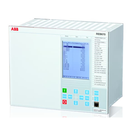
Section 5 1MRK 505 337-UUS - Local HMI Section 5 Local HMI ANSI13000239-2-en.vsd ANSI13000239 V2 EN Figure 33: Local human-machine interface The LHMI of the IED contains the following elements: Application manual... -
Page 98: Display
Section 5 1MRK 505 337-UUS - Local HMI • Keypad • Display (LCD) • LED indicators • Communication port for PCM600 The LHMI is used for setting, monitoring and controlling. Display The LHMI includes a graphical monochrome liquid crystal display (LCD) with a resolution of 320 x 240 pixels. - Page 99 Section 5 1MRK 505 337-UUS - Local HMI IEC15000270-1-en.vsdx IEC15000270 V1 EN Figure 34: Display layout 1 Path 2 Content 3 Status 4 Scroll bar (appears when needed) The function key button panel shows on request what actions are possible with the function buttons.
- Page 100 Section 5 1MRK 505 337-UUS - Local HMI IEC13000281-1-en.vsd GUID-C98D972D-D1D8-4734-B419-161DBC0DC97B V1 EN Figure 35: Function button panel The indication LED panel shows on request the alarm text labels for the indication LEDs. Three indication LED pages are available. IEC13000240-1-en.vsd GUID-5157100F-E8C0-4FAB-B979-FD4A971475E3 V1 EN Figure 36: Indication LED panel The function button and indication LED panels are not visible at the same time.
-
Page 101: Leds
Section 5 1MRK 505 337-UUS - Local HMI LEDs The LHMI includes three protection status LEDs above the display: Normal, Pickup and Trip. There are 15 programmable indication LEDs on the front of the LHMI. Each LED can indicate three states with the colors: green, yellow and red. The texts related to each three- color LED are divided into three panels. - Page 102 Section 5 1MRK 505 337-UUS - Local HMI ANSI15000157-1-en.vsdx ANSI15000157 V1 EN Figure 37: LHMI keypad with object control, navigation and command push-buttons and RJ-45 communication port 1...5 Function button Close Open Escape Left Down Right Enter Remote/Local Uplink LED Not in use Multipage Application manual...
-
Page 103: Local Hmi Functionality
Section 5 1MRK 505 337-UUS - Local HMI Menu Clear Help Communication port Programmable indication LEDs IED status LEDs Local HMI functionality 5.4.1 Protection and alarm indication Protection indicators The protection indicator LEDs are Normal, Pickup and Trip. Table 8: Normal LED (green) LED state Description... -
Page 104: Parameter Management
Section 5 1MRK 505 337-UUS - Local HMI Table 10: Trip LED (red) LED state Description Normal operation. A protection function has tripped. An indication message is displayed if the auto-indication feature is enabled in the local HMI. The trip indication is latching and must be reset via communication, LHMI or binary input on the LEDGEN component. -
Page 105: Front Communication
Section 5 1MRK 505 337-UUS - Local HMI Numerical values are presented either in integer or in decimal format with minimum and maximum values. Character strings can be edited character by character. Enumerated values have a predefined set of selectable values. 5.4.3 Front communication The RJ-45 port in the LHMI enables front communication. -
Page 107: Section 6 Differential Protection
Section 6 1MRK 505 337-UUS - Differential protection Section 6 Differential protection Busbar differential protection 6.1.1 Identification Busbar differential protection, 3-phase version IEC 61850 IEC 60617 ANSI/IEEE C37.2 Function description identification identification device number Busbar differential protection, 2 zones, 3Id/I BUTPTRC three phase/4 bays SYMBOL-JJ V1 EN... - Page 108 Section 6 1MRK 505 337-UUS - Differential protection Busbar differential protection, 1-phase version Function description IEC 61850 IEC 60617 ANSI/IEEE C37.2 identification identification device number Busbar differential protection, 2 zones, 3Id/I BUSPTRC single phase/12 or 24 bays SYMBOL-JJ V1 EN Busbar differential protection, 2 zones, 3Id/I BCZSPDIF...
-
Page 109: Basic Applications
6.1.2.1 General Basic types of applications for REB670 IED are shown and described in this chapter. For these applications usually three phase version of the IED, with two differential zone and four (or even eight) 3-phase CT inputs, is used. -
Page 110: Distinctive Features Of Busbar Protection Schemes
Section 6 1MRK 505 337-UUS - Differential protection as a delayed tripping for busbar faults can also lead to network instability, pole slip of near- by generators and even total system collapse. For bus zone protection applications, it is extremely important to have good security since an unwanted operation might have severe consequences. - Page 111 Section 6 1MRK 505 337-UUS - Differential protection busbar differential IEDs do not measure directly the primary currents in the high voltage conductors, but the secondary currents of magnetic core current transformers (that is, CTs), which are installed in all high-voltage bays connected to the busbar. Therefore, the busbar differential IED is unique in this respect, that usually quite a few CTs, often with very different ratios and classes, are connected to the same differential protection zone.
- Page 112 IED, the IED algorithm would be quite complex. Thus, it was decided to re-use the ABB excellent experience from the analog percentage restrained differential protection IED (that is, RADSS and REB 103), and use only the following...
-
Page 113: Zone Selection (Ct Switching)
Traditionally, the CT switching has been done in CT secondary circuits. However, with REB670 this is not the case. All necessary zone selection (that is, CT switching) is done in software. Therefore, the CT secondary circuits are always intact and without any auxiliary relay contacts. -
Page 114: Minimum Contact Requirements
Section 6 1MRK 505 337-UUS - Differential protection 6.1.3.6 Minimum contact requirements The minimum requirement for the busbar replica is the record of the disconnector position by using just one auxiliary contact, either NO or NC type. However recording a pair of auxiliary contacts, representing the OPEN and CLOSE position, offer additional features which can improve the reliability of the bus replica including supervision possibilities. - Page 115 Section 6 1MRK 505 337-UUS - Differential protection Table 12: Treatment of primary object auxiliary contact status within BBP in REB670 Primary equipment Status in busbar protection Alarm facility Normally Normally when when Alarm after Information visible on Open Closed “Scheme 1...
- Page 116 Section 6 1MRK 505 337-UUS - Differential protection arcing possible closed open N.O. input „closed“ N.C. input „open“ current assignment 1) disconnector supervision running 2) BI „closed“ should change before arcing distance en06000085.vsd IEC06000085 V1 EN Figure 41: Scheme2_INX Circuit breaker replica The circuit breaker position from a bay shall be given to the busbar protection when the position of this particular breaker can influence the busbar protection operation.
-
Page 117: Zone Selection Features
Section 6 1MRK 505 337-UUS - Differential protection 189G en06000086_ansi.vsd ANSI06000086 V1 EN Figure 42: Feeder bay layout when line disconnector position might be required for busbar protection Such feeder set-up can be often found in GIS stations where cable CTs are used for busbar protection. - Page 118 Section 6 1MRK 505 337-UUS - Differential protection FIXEDtoZA FIXEDtoZB FIXEDtoZA&-ZB CtrlIncludes CtrlExcludes If for a particular CT input setting parameter ZoneSel is set to FIXEDtoZA, then this CT input will be only included to the differential zone A. This setting is typically used for simple single zone application such as: single busbar staions, breaker-and-a-half stations or double breaker stations.
-
Page 119: Ct Disconnection For Bus Section And Bus Coupler Current Transformer Cores
Section 6 1MRK 505 337-UUS - Differential protection This setting is typically used for feeder bays in double busbar single breaker stations in order to form proper busbar disconnector replica. It is especially suitable when only normally closed (that is, b) auxiliary contact from the busbar disconnector(s) is available to the IED. - Page 120 Section 6 1MRK 505 337-UUS - Differential protection protection scheme for this type of stations. In such application the bus section or bus coupler current transformers shall be wired just to two separate current input of the IED. Then in the parameter setting tool (PST) for the corresponding bays the parameter ZoneSel shall be set to FIXEDtoZA in one bay and FIXEDtoZB in another bay.
- Page 121 It directly follows the philosophy used for RADSS/REB 103 schemes used for similar applications before. Principle connection between the bus- coupler CB normally closed auxiliary contact (b-contact), REB670 and internal configuration logic, as shown in figure...
- Page 122 Section 6 1MRK 505 337-UUS - Differential protection This scheme will disconnect the section/coupler CTs after about 80 ms (pre-set time under parameter setting tZeroCurrent in the relevant bay function block) from the moment of opening of the section/coupler CB ( that is, from the moment when auxiliary b contact makes).
-
Page 123: End Fault Protection
Section 6 1MRK 505 337-UUS - Differential protection Zone A Zone B REB 670 0-tOFF EXTSTART ACTIVE ALARM Indication that Zone interconnection is active Bus coupler en06000137_ansi.vsd ANSI06000137 V1 EN Figure 47: Configuration logic for bus coupler without main CTs 6.1.3.10 End fault protection When Live tank CBs or GIS are involved, there is a physical separation between the CT... - Page 124 Section 6 1MRK 505 337-UUS - Differential protection Busbar Protection Busbar Busbar Protection Protection Feeder Feeder Protection Protection Feeder Protection en06000138_ansi.vsd ANSI06000138 V1 EN Figure 48: Typical CT locations in a feeder bay where: = two CTs are available one on each side of the feeder circuit breaker = one CT is available on the line side of the feeder circuit breaker = one CT is available on the bus side of the feeder circuit breaker = End fault region...
- Page 125 Section 6 1MRK 505 337-UUS - Differential protection xx06000139_ansi.vsd ANSI06000139 V1 EN Figure 49: Busbar protection measuring and fault clearing boundaries where: is Busbar Protection measuring boundary determined by feeder CT locations is Busbar Protection internal fault clearing boundary determined by feeder CB locations is End fault region for feeders as shown in figure 48/B is End fault region for feeders as shown in figure 48/C In figure...
-
Page 126: Zone Interconnection (Load Transfer)
Section 6 1MRK 505 337-UUS - Differential protection • For feeders with CT on the line side of the circuit breaker (that is, two feeders on the left-hand side in figure 49), the current measurement can be disconnected from the busbar protection zone some time after feeder CB opening (for example, 400 ms for transformer and cable feeders or longest autoreclosing dead time +300 ms for overhead line feeders). - Page 127 Section 6 1MRK 505 337-UUS - Differential protection (189 and 289) the opening of the bus coupler circuit breaker is sometimes interlocked while both busbar disconnectors within one of the feeder bays are closed. • opening of the feeder bay busbar disconnector originally closed. The load is now transferred from one to other bus.
- Page 128 Section 6 1MRK 505 337-UUS - Differential protection value or active binary input, while zone switching feature is active within the IED. This setting is typically used for bus coupler bay in double busbar stations. If for a particular CT input setting parameter ZoneSwitching is set to ForceIn, then this CT input will be connected to both the differential zones, regardless of any other set value or active binary input, while zone switching feature is active within the IED.
- Page 129 Section 6 1MRK 505 337-UUS - Differential protection Sensitive differential protection Operate region Differential protection operation characteristic Diff Oper Level Sens Iin Block Sensitive Oper Level s=0.53 [Primary Amps] en06000142.vsd IEC06000142 V1 EN Figure 50: Differential protection operation characteristic Additionally the sensitive differential protection can be time delayed and it must be externally enabled by a binary signal (that is, from external open delta VT overvoltage relay or power transformer neutral point overcurrent relay).
- Page 130 Section 6 1MRK 505 337-UUS - Differential protection Operate region Oper Level s=0.0-0.90 (settable) [Primary Amps] en06000062.vsd IEC06000062 V1 EN Figure 51: Check zone operation characteristic Note that the check zone minimum differential operational level OperLevel shall be set equal to or less than the corresponding operating level of the usual discriminating zones. For substations where traditional “CT switching”...
-
Page 131: Tripping Circuit Arrangement
CT secondary circuits caused by accidents or mistakes. • internal check zone feature is available This means that a very cost effective solution can be achieved using REB670, producing extra savings during scheme engineering, installation, commissioning, service and maintenance. -
Page 132: Trip Arrangement With One-Phase Version
Section 6 1MRK 505 337-UUS - Differential protection 6.1.3.13 Trip arrangement with one-phase version When one-phase version of the IED is used it is typically required to have three IEDs (that is, one per phase). Thus, when busbar protection in one IED operates the trip commands will be given to all bays but internal circuit breaker failure function will be started in the same phase only. -
Page 133: Centralized Trip Unit
Section 6 1MRK 505 337-UUS - Differential protection GOOSE for ZoneA ZoneA Trip IED 670 GOOSE for ZoneB ZoneB Trip 50 ms Ext ZoneA Trip Switch IED 670 50 ms Ext ZoneB Trip 50 ms Ext ZoneA Trip IED 670 50 ms Ext ZoneB Trip en06000227.vsd... -
Page 134: Mechanical Lock-Out Function
Section 6 1MRK 505 337-UUS - Differential protection contacts are required and only RXMS 1/AR relays when medium duty contacts are sufficient. This solution is especially suitable for the station arrangements, which require the dynamic zone selection logic (that is, so called CT switching). 6.1.3.16 Mechanical lock-out function It is sometimes required to use lock-out relays for busbar protection operation. -
Page 135: Trip Circuit Supervision For Busbar Protection
Section 6 1MRK 505 337-UUS - Differential protection 6.1.3.18 Trip circuit supervision for busbar protection Trip circuit supervision is mostly required to supervise the trip circuit from the individual bay IED panel to the circuit breaker. It can be arranged also for the tripping circuits from the busbar protection. -
Page 136: Single Busbar Arrangements With Sectionalizer
1Ph; 2-zones, 12-bays BBP (B20) 1Ph; 2-zones, 12-bays BBP (B21) 1Ph; 2-zones, 24-bays BBP (B31) Please note that the above table is given for the preconfigured versions of REB670 which do not contain any VT inputs. 6.1.4.3 Single busbar arrangements with sectionalizer This arrangement is very similar to the single busbar arrangement. -
Page 137: Single Busbar Arrangements With Bus-Section Breaker
1Ph; 2-zones, 24-bays BBP (B31) Please note that table is given for the preconfigured versions of REB670 which do not contain any VT inputs. Two differential zones are available in the IED and the connecting of the two zones is simply controlled via zone interconnection logic, as described in section "Zone... -
Page 138: H-Type Busbar Arrangements
CT input from bus-section bay Please note that table is given for the preconfigured versions of REB670 which do not contain any VT inputs. For station with just one CT in the bus-section bay, it might be required, depending on the client requirements, to provide the special scheme for disconnection of bus-section CT when the bus-section CB is open. - Page 139 Section 6 1MRK 505 337-UUS - Differential protection busbar station with sectionalizer or bus-section breaker, but are characterized by very limited number of feeder bays connected to the station (normally only two OHL and two transformers). xx06000121_ansi.vsd ANSI06000121 V1 EN Figure 56: Example of H-type station The requirement for the busbar protection scheme for this type of station may differ from...
-
Page 140: Double Circuit Breaker Busbar Arrangement
1Ph; 2-zones, 24-bays BBP (B31) Please note that table is given for the preconfigured versions of REB670 which do not contain any VT inputs. For station with double zone protection and just one set of CTs in the bus-section bay, it might be required, depending on the client requirements, to provide the special scheme for disconnection of bus-section CT when the bus-section CB is open. - Page 141 Please note that table is given for the preconfigured versions of REB670 which do not contain any VT inputs. A principle overall drawing of how to use REB670 for this type of station is given in figure 58. Application manual...
-
Page 142: Breaker-And-A-Half Busbar Arrangements
Section 6 1MRK 505 337-UUS - Differential protection REB 670 Bxxx BBP & Zone A BLKTR TRIP TRIP CTRLZA 152 Internal BFP CONNZA Backup Trip Command CTRLZB CONNZB TRZONE Parameter ZoneSel must CT Input TRBAY be set to "FixedToZA" I3PB1 Other Equipment CT Input... - Page 143 3PH; 2-zones, 8-bays BBP (A31) 1Ph; 2-zones, 12-bays BBP (B20) 6/12 1Ph; 2-zones, 12-bays BBP (B21) 6/12 1Ph; 2-zones, 24-bays BBP (B31) 12/24 Please note that table is given for the preconfigured versions of REB670 which do not contain any VT inputs. Application manual...
-
Page 144: Double Busbar Single Breaker Arrangement
Section 6 1MRK 505 337-UUS - Differential protection A principle overall drawing of how to use REB670 for breaker-and-a-half station including internal CBF protection for middle breaker is given in figure 60. REB 670 Remote Inter- Bxxx Trip Zone A... - Page 145 1Ph; 2-zones, 12-bays BBP (B21) 1Ph; 2-zones, 24-bays BBP (B31) *) with just one CT input from bus-coupler bay Please note that table is given for the preconfigured versions of REB670 which do not contain any VT inputs. Application manual...
- Page 146 CT when the bus-coupler CB is open. For more info please refer to figure 45. Some principle overall drawings of how to use REB670 in this type of station are given in figure to figure 66.
- Page 147 Section 6 1MRK 505 337-UUS - Differential protection Zone A Disconnector aux. contact timing Zone B Main Open Closed contact Aux . b Closed Open contact REB 670 Set Parameter ZoneSel=" CtrlExcludes" External or Internal Feeder BFP Backup Bxxx Trip Command BLKTR TRIP CTRLZA...
- Page 148 Section 6 1MRK 505 337-UUS - Differential protection Zone A Zone B REB 670 Parameter ZoneSel must be set to "FixedToZA" Bxxx BLKTR TRIP CTRLZA CONNZA CTRLZB Other CONNZB Equipment TRZONE CT Input TRBAY I3PB1 External or Internal Bus-Coupler BFP Backup Trip Command Bus-Coupler Bxxx...
- Page 149 Section 6 1MRK 505 337-UUS - Differential protection Zone A Zone B REB 670 CB Closing Signal t=1s SSxx DISABLE CLOSED OPEN Bxxx ALARM BLKTR TRIP FORCED CTRLZA CONNZA CTRLZB CONNZB External or Internal ZEROCUR Bus-Coupler BFP Bus-Coupler TRZONE Backup Trip Command TRBAY I3PB1 Bus-Coupler Backup...
-
Page 150: Double Busbar Arrangements With Two Bus-Section Breakers And Two Bus-Coupler Breakers
Section 6 1MRK 505 337-UUS - Differential protection Zone A Zone B REB 670 t=1s Bxxx BLKTR TRIP CTRLZA CB Closing CONNZA Signal CTRLZB CONNZB External or Internal ZEROCUR Bus-Coupler BFP Bus-Coupler TRZONE Backup Trip Command TRBAY I3PB1 Bus-Coupler Backup OC Trip Parameter ZoneSel must CT Input... -
Page 151: Double Busbar-Single Breaker With Transfer Bus Arrangements
Section 6 1MRK 505 337-UUS - Differential protection With REB670 this type of arrangement can be protected as described in the following table. Table 20: Possible solutions for a typical GIS station Version of REB670 IED Number of feeders on... - Page 152 This type of busbar arrangement can be protected as described in the following table: Table 21: Possible solutions for double busbar-single breaker with transfer bus arrangements Version of REB670 IED Total number of feeder Number of REB670 IEDs bays in the station required for the scheme (excluding buscoupler &...
-
Page 153: Combined Busbar Arrangements
1MRK 505 337-UUS - Differential protection Please note that table is given for the preconfigured versions of REB670 which do not contain any VT inputs. Note that for station layouts where combined transfer and bus-coupler bay is used, as for example is shown in figure 68, two internal bay function blocks must be allocated to such primary bay, reducing number of available feeder bays. - Page 154 3PH; 2-zones, 8-bays BBP (A31) 1Ph; 2-zones, 12-bays BBP (B20) 1Ph; 2-zones, 12-bays BBP (B21) 1Ph; 2-zones, 24-bays BBP (B31) 3/18 Please note that table is given for the preconfigured versions of REB670 which do not contain any VT inputs. Application manual...
-
Page 155: Summation Principle
Section 6 1MRK 505 337-UUS - Differential protection xx06000125_ansi.vsd ANSI06000125 V1 EN Figure 71: Combination between one-and-half breaker and double busbar station layouts For this type of busbar arrangement the double busbar bay is usually connected to the reactive power compensation equipment (that is, shunt reactor or shunt capacitor). The diameters in the one-and-half breaker part of the station have at the same time the role of the bus-coupler bay. - Page 156 Difference between phase segregated & summation type differential protection In the full, phase-segregated design three, one-phase REB670 IEDs (that is, one per phase) are used. However for the summation type only single, one-phase REB670 IED plus one auxiliary summation CT per each main CT is required. These auxiliary summation CTs convert each main CT three-phase currents to a single-phase output current, which are all measured by one REB670 IED.
- Page 157 Section 6 1MRK 505 337-UUS - Differential protection Main CTs A-bus Summation CTs . . . CT24 with 1A CT inputs ANSI06000127_2_en.vsd ANSI06000127 V2 EN Figure 73: Principle CT connections for the complete station This summation type bus differential protection still has the same main CT requirements as outlined in section "".
-
Page 158: Auxiliary Summation Cts
The ASCT has three primary windings and one secondary winding. In further text, turn numbers of these windings will be marked with N1, N2, N3 & N4, respectively (see figure for more information). There are three types of ASCT for REB670: Application manual... - Page 159 Section 6 1MRK 505 337-UUS - Differential protection ASCT type with ratio 1/1A, for balanced 3-Ph current input, shall be used with all main current transformers with 1A rated secondary current (that is, 2000/1A) ASCT type with ratio 5/1A, for balanced 3-Ph current input, shall be used with all main current transformers with 5A rated secondary current (that is, 3000/5A) ASCT type with ratio 2/1A, for balanced 3-Ph current input, shall be used with all main current transformers with 2A rated secondary current (that is, 1000/2A)
-
Page 160: Possible Asct Connections For Reb670
Section 6 1MRK 505 337-UUS - Differential protection 6.1.5.3 Possible ASCT connections for REB670 It is possible to connect the ASCTs for summated bus differential protection with REB670: • at the end of the main CT circuit (for example, beyond the other protective relays, as shown in figure •... -
Page 161: Main Ct Ratio Mismatch Correction
The entered value, for the minimal differential operating current level, will exactly correspond to the REB670 pickup value in the event of a 3-phase internal fault. For all other fault types this Application manual... - Page 162 Section 6 1MRK 505 337-UUS - Differential protection value must be multiplied by a coefficient shown in the table in order to calculate the actual primary pickup value. Table 24: Pickup coefficients for Summated Differential Protection Type of fault A-Gnd B-Gnd C-Gnd ASCT end...
- Page 163 Section 6 1MRK 505 337-UUS - Differential protection Table 25: Functions Functions Comment Busbar Differential Protection Differential Protection, Sensitive differential protection, OCT algorithm, Check Zone and Differential Supervision features will be connected to the summated bay currents. Therefore, they will have different level depending on the type of fault and involved phase(s).
-
Page 164: Slce 8/Asct Characteristics For End-Connection
IA N IA IB IA IB SUMM (Equation 15) EQUATION1785-ANSI V1 EN The relationships between number of turns for this SLCE 8, ASCT for REB670, is shown in equation 16, equation and equation 18: (Equation 16) EQUATION1108 V1 EN ×... -
Page 165: Slce 8/Asct Characteristics For Series-Connection
N IA IB IC × SUMM (Equation 21) EQUATION1787-ANSI V1 EN The relationships between the number of turns for this SLCE 8 ASCT for REB670, is shown in equation 22, equation 23, equation 24: (Equation 22) EQUATION1108 V1 EN ×... - Page 166 Section 6 1MRK 505 337-UUS - Differential protection × × (Equation 24) EQUATION1110 V1 EN where: is a constant, which depends on the type of ASCT (that is, k=1, for 1/1A ASCT or k=5 for 5/1A ASCT or k=2 for 2/1A ASCT). The well-known relationship, between positive, negative and zero sequence current components and individual phase current quantities is shown in equation 25: é...
-
Page 167: Section 7 Current Protection
Section 7 1MRK 505 337-UUS - Current protection Section 7 Current protection Four step phase overcurrent protection OC4PTOC(51/67) 7.1.1 Identification Function description IEC 61850 IEC 60617 ANSI/IEEE C37.2 identification identification device number Four step phase overcurrent protection OC4PTOC 51_67 3-phase output TOC-REVA V2 EN 7.1.2 Application... -
Page 168: Setting Guidelines
Section 7 1MRK 505 337-UUS - Current protection Non-directional / Directional function: In most applications the non-directional functionality is used. This is mostly the case when no fault current can be fed from the protected object itself. In order to achieve both selectivity and fast fault clearance, the directional function can be necessary. - Page 169 Section 7 1MRK 505 337-UUS - Current protection time delay. Thus, if only the inverse time delay is required, it is important to set the definite time delay for that stage to zero. The parameters for Four step phase overcurrent protection 3-phase output OC4PTOC (51/67) are set via the local HMI or PCM600.
-
Page 170: Settings For Each Step
Section 7 1MRK 505 337-UUS - Current protection ANSI09000636-1-en.vsd ANSI09000636 V1 EN Figure 77: Directional function characteristic 1. RCA = Relay characteristic angle 2. ROA = Relay operating angle 3. Reverse 4. Forward 7.1.3.1 Settings for each step x means step 1, 2, 3 and 4. DirModeSelx: The directional mode of step x. - Page 171 Section 7 1MRK 505 337-UUS - Current protection Characteristx: Selection of time characteristic for step x. Definite time delay and different types of inverse time characteristics are available according to table 26. Table 26: Inverse time characteristics Curve name ANSI Extremely Inverse ANSI Very Inverse ANSI Normal Inverse ANSI Moderately Inverse...
- Page 172 Section 7 1MRK 505 337-UUS - Current protection I3>MaxEd2Set: Maximum settable operating phase current level for step 3 in % of IBase, for 61850 Ed.2 settings I4>MinEd2Set: Minimum settable operating phase current level for step 4 in % of IBase, for 61850 Ed.2 settings I4>MaxEd2Set: Maximum settable operating phase current level for step 4 in % of IBase, for 61850 Ed.2 settings...
- Page 173 Section 7 1MRK 505 337-UUS - Current protection Operate time txMin IMinx Current IEC10000058 IEC10000058 V2 EN Figure 78: Minimum operate current and operation time for inverse time characteristics In order to fully comply with curves definition setting parameter txMin shall be set to the value, which is equal to the operating time of the selected inverse curve for measured current of twenty times the set current pickup value.
-
Page 174: 2Nd Harmonic Restrain
Section 7 1MRK 505 337-UUS - Current protection For IEC inverse time characteristics the possible delay time settings are instantaneous (1) and IEC (2 = set constant time reset). For the customer tailor made inverse time delay characteristics (type 17) all three types of reset time characteristics are available;... - Page 175 Section 7 1MRK 505 337-UUS - Current protection HarmRestrainx: This parameter can be set Disabled/Enabled, to disable or enable the 2nd harmonic restrain. The four step phase overcurrent protection 3-phase output can be used in different ways, depending on the application where the protection is used. A general description is given below.
- Page 176 Section 7 1MRK 505 337-UUS - Current protection Im ax ³ × Ipu 1.2 (Equation 28) EQUATION1262 V2 EN where: is a safety factor is the resetting ratio of the protection Imax is the maximum load current From operation statistics the load current up to the present situation can be found. The current setting must be valid also for some years ahead.
- Page 177 Section 7 1MRK 505 337-UUS - Current protection (primary protected zone). A fault current calculation gives the largest current of faults, Iscmax, at the most remote part of the primary protected zone. Considerations have to be made to the risk of transient overreach, due to a possible DC component of the short circuit current.
- Page 178 Section 7 1MRK 505 337-UUS - Current protection en05000204.wmf IEC05000204 V1 EN Figure 80: Fault time with maintained selectivity The operation time can be set individually for each overcurrent protection. To assure selectivity between different protections, in the radial network, there have to be a minimum time difference Dt between the time delays of two protections.
- Page 179 Section 7 1MRK 505 337-UUS - Current protection Example for time coordination Assume two substations A and B directly connected to each other via one line, as shown in the figure 81. Consider a fault located at another line from the station B. The fault current to the overcurrent protection of IED B1 has a magnitude so that the protection will have instantaneous function.
-
Page 180: Four Step Single Phase Overcurrent Protection Ph4Sptoc (51)
Section 7 1MRK 505 337-UUS - Current protection D ³ (Equation 32) EQUATION1266 V1 EN where it is considered that: the operate time of overcurrent protection B1 is 40 ms the breaker open time is 100 ms the resetting time of protection A1 is 40 ms and the additional margin is 40 ms... -
Page 181: Setting Guidelines
Section 7 1MRK 505 337-UUS - Current protection In many applications several steps with different current pick up levels and time delays are needed. PH4SPTOC(51) can have up to four different, individual settable, steps. The flexibility of each step of PH4SPTOC(51) function is great. The following options are possible: Choice of delay time characteristics: There are several types of time delay characteristics available such as definite time delay and different types of inverse time delay... -
Page 182: Settings For Each Step (X = 1-4)
Section 7 1MRK 505 337-UUS - Current protection 2ndHarmStab: Operate level of 2 harmonic current restrain set in % of the fundamental current. The setting range is 5-100% of IBase in steps of 1%. Default setting is 20%. HarmRestrainx: Disabled/Enabled, enables blocking from harmonic restrain. 7.2.3.1 Settings for each step (x = 1-4) Characteristx: Selection of time delay characteristic for step x. - Page 183 Section 7 1MRK 505 337-UUS - Current protection InxMult: Multiplier for scaling of the current setting value. If a binary input signal (enableMultiplier) is activated the current operation level is increase by this setting constant. Setting range: 1.0-10.0 txMin: Minimum operation time for IEC inverse time characteristics. At high currents the inverse time characteristic might give a very short operation time.
-
Page 184: Second Harmonic Restrain
Section 7 1MRK 505 337-UUS - Current protection æ ö ç ÷ ç ÷ × IxMult ç ÷ æ ö ç ç ÷ ÷ è è ø ø > (Equation 33) EQUATION1261 V2 EN For more information, please refer to the “Technical reference manual”. tPRCrvx, tTRCrvx, tCRCrvx: Parameters for customer creation of inverse reset time characteristic curve (Reset Curve type = 3). - Page 185 Section 7 1MRK 505 337-UUS - Current protection Current I Line phase current Operate current Reset current The IED does not reset Time t IEC05000203-en-2.vsd IEC05000203 V3 EN Figure 82: Pick up and reset current for an overcurrent protection The lowest setting value can be written according to equation 34. Im ax ³...
- Page 186 Section 7 1MRK 505 337-UUS - Current protection disconnectors. The manufacturer of the equipment normally gives the maximum thermal load current of the equipment. There is also a demand that all faults, within the zone that the protection shall cover, must be detected by the phase overcurrent protection.
- Page 187 Section 7 1MRK 505 337-UUS - Current protection The operate times of the phase overcurrent protection has to be chosen so that the fault time is so short so that equipment will not be destroyed due to thermal overload, at the same time as selectivity is assured.
- Page 188 Section 7 1MRK 505 337-UUS - Current protection protection operation time: 15-60 ms protection resetting time: 15-60 ms Breaker opening time: 20-120 ms Example Assume two substations A and B directly connected to each other via one line, as shown in the figure below.
-
Page 189: Four Step Residual Overcurrent Protection, (Zero Sequence Or Negative Sequence Directionality) Ef4Ptoc (51N/67N)
Section 7 1MRK 505 337-UUS - Current protection are uncertainties in the values of protection operation time, breaker opening time and protection resetting time. Therefor a safety margin has to be included. With normal values the needed time difference can be calculated according to equation 38. D ³... -
Page 190: Settings For Each Step (X = 1, 2, 3 And 4)
Section 7 1MRK 505 337-UUS - Current protection GlobalBaseSel: Selects the global base value group used by the function to define (IBase), (VBase) and (SBase). Operation: Sets the protection to Enabled or Disabled. 7.3.2.1 Settings for each step (x = 1, 2, 3 and 4) DirModeSelx: The directional mode of step x. - Page 191 Section 7 1MRK 505 337-UUS - Current protection IN1>MinEd2Set: Minimum operate residual current level for step 1 in % of IBase, for 61850 Ed.2 settings IN1>MaxEd2Set: Maximum operate residual current level for step 1 in % of IBase, for 61850 Ed.2 settings IN2>MinEd2Set:: Minimum operate residual current level for step 2 in % of IBase, for 61850 Ed.2 settings IN2>MaxEd2Set:: Maximum operate residual current level for step 2 in % of IBase, for...
-
Page 192: Common Settings For All Steps
Section 7 1MRK 505 337-UUS - Current protection In order to fully comply with curves definition the setting parameter txMin shall be set to the value which is equal to the operate time of the selected IEC inverse curve for measured current of twenty times the set current pickup value. - Page 193 Section 7 1MRK 505 337-UUS - Current protection V pol = 3V or V Operation IDirPU en 05000135-4- ansi. vsd ANSI05000135 V3 EN Figure 86: Relay characteristic angle given in degree In a normal transmission network a normal value of RCA is about 65°. The setting range is -180°...
-
Page 194: 2Nd Harmonic Restrain
Section 7 1MRK 505 337-UUS - Current protection protection. The maximum ground-fault current at the local source can be used to calculate the value of ZN as V/(√3 · 3I ) Typically, the minimum ZNPol (3 · zero sequence source) is set. -
Page 195: Switch Onto Fault Logic
Section 7 1MRK 505 337-UUS - Current protection the inrush currents of the two transformers will be in phase opposition. The summation of the two currents will thus give a small 2 harmonic current. The residual fundamental current will however be significant. The inrush current of the transformer in service before the parallel transformer energizing, will be a little delayed compared to the first transformer. -
Page 196: Four Step Directional Negative Phase Sequence Overcurrent Protection Ns4Ptoc (46I2)
Section 7 1MRK 505 337-UUS - Current protection SOTF and Under Time are similar functions to achieve fast clearance at asymmetrical closing based on requirements from different utilities. The function is divided into two parts. The SOTF function will give operation from step 2 or 3 during a set time after change in the position of the circuit breaker. -
Page 197: Identification
Section 7 1MRK 505 337-UUS - Current protection 7.4.1 Identification Function description IEC 61850 IEC 60617 identification ANSI/IEEE C37.2 identification device number Four step negative sequence NS4PTOC 46I2 overcurrent protection IEC10000053 V1 EN 7.4.2 Application Four step negative sequence overcurrent protection NS4PTOC (4612) is used in several applications in the power system. - Page 198 Section 7 1MRK 505 337-UUS - Current protection ordination between the operating time of the different protections. To enable optimal co- ordination all overcurrent relays, to be co-ordinated against each other, should have the same time characteristic. Therefore a wide range of standardized inverse time characteristics are available: IEC and ANSI.
-
Page 199: Setting Guidelines
Section 7 1MRK 505 337-UUS - Current protection 7.4.3 Setting guidelines The parameters for Four step negative sequence overcurrent protection NS4PTOC (46I2) are set via the local HMI or Protection and Control Manager (PCM600). The following settings can be done for the four step negative sequence overcurrent protection: Operation: Sets the protection to Enabled or Disabled. - Page 200 Section 7 1MRK 505 337-UUS - Current protection Curve name IEC Very Inverse IEC Inverse IEC Extremely Inverse IEC Short Time Inverse IEC Long Time Inverse IEC Definite Time User Programmable ASEA RI RXIDG (logarithmic) The different characteristics are described in the Technical Reference Manual (TRM). Pickupx: Operation negative sequence current level for step x given in % of IBase.
- Page 201 Section 7 1MRK 505 337-UUS - Current protection Operate time txMin IMinx Current IEC10000058 IEC10000058 V2 EN Figure 88: Minimum operate current and operation time for inverse time characteristics ResetTypeCrvx: The reset of the delay timer can be made in different ways. By choosing setting there are the following possibilities: Curve name Instantaneous...
-
Page 202: Common Settings For All Steps
Section 7 1MRK 505 337-UUS - Current protection tPCrvx, tACrvx, tBCrvx, tCCrvx: Parameters for programmable inverse time characteristic curve. The time characteristic equation is according to equation 39: æ ö ç ÷ ç ÷ × ç ÷ æ ö ç ÷... -
Page 203: Thermal Overload Protection, Two Time Constants Trpttr (49)
Section 7 1MRK 505 337-UUS - Current protection Reverse Area AngleRCA Vpol=-V2 Forward Area Iop = I2 ANSI10000031-1-en.vsd ANSI10000031 V1 EN Figure 89: Relay characteristic angle given in degree In a transmission network a normal value of RCA is about 80°. VPolMin: Minimum polarization (reference) voltage % of VBase. -
Page 204: Identification
Section 7 1MRK 505 337-UUS - Current protection 7.5.1 Identification Function description IEC 61850 IEC 60617 ANSI/IEEE C37.2 identification identification device number Thermal overload protection, two time TRPTTR constants SYMBOL-A V1 EN 7.5.2 Application Transformers in the power system are designed for a certain maximum load current (power) level. -
Page 205: Setting Guideline
Section 7 1MRK 505 337-UUS - Current protection If the heat content of the protected transformer reaches a set alarm level a signal can be given to the operator. Two alarm levels are available. This enables preventive actions in the power system to be taken before dangerous temperatures are reached. If the temperature continues to increase to the trip value, the protection initiates a trip of the protected transformer. - Page 206 Section 7 1MRK 505 337-UUS - Current protection Tau1: The thermal time constant of the protected transformer, related to IBase1 (no cooling) given in minutes. Tau2: The thermal time constant of the protected transformer, related to IBase2 (with cooling) given in minutes. The thermal time constant should be obtained from the transformer manufacturers manuals.
-
Page 207: Breaker Failure Protection Ccrbrf(50Bf)
Section 7 1MRK 505 337-UUS - Current protection • In case a total interruption (low current) of the protected transformer all cooling possibilities will be inactive. This can result in a changed value of the time constant. • If other components (motors) are included in the thermal protection, there is a risk of overheating of that equipment in case of very high current. -
Page 208: Application
Section 7 1MRK 505 337-UUS - Current protection 7.6.2 Application In the design of the fault clearance system the N-1 criterion is often used. This means that a fault needs to be cleared even if any component in the fault clearance system is faulty. One necessary component in the fault clearance system is the circuit breaker. - Page 209 Section 7 1MRK 505 337-UUS - Current protection Table 32: Dependencies between parameters RetripMode and FunctionMode RetripMode FunctionMode Description Retrip Off the re-trip function is not activated CB Pos Check Current a phase current must be larger than the operate level to allow re- trip Contact re-trip is done when breaker...
- Page 210 Section 7 1MRK 505 337-UUS - Current protection t1: Time delay of the re-trip. The setting can be given within the range 0 – 60s in steps of 0.001 s. Typical setting is 0 – 50ms. t2: Time delay of the back-up trip. The choice of this setting is made as short as possible at the same time as unwanted operation must be avoided.
- Page 211 Section 7 1MRK 505 337-UUS - Current protection Protection operate time Normal t cbopen Retrip delay t1 after re-trip The fault cbopen occurs BFPreset Margin Minimum back-up trip delay t2 Critical fault clearance time for stability Time Trip and Pickup CCRBRF (50BF) ANSI05000479_3_en.vsd...
-
Page 212: Breaker Failure Protection, Single Phase Version Ccsrbrf (50Bf)
Section 7 1MRK 505 337-UUS - Current protection Breaker failure protection, single phase version CCSRBRF (50BF) 7.7.1 Identification Function description IEC 61850 IEC 60617 ANSI/IEEE C37.2 identification identification device number Breaker failure protection, single phase CCSRBRF 50BF version I>BF SYMBOL-II V1 EN 7.7.2 Application In the design of the fault clearance system the N-1 criterion is often used. - Page 213 Section 7 1MRK 505 337-UUS - Current protection FunctionMode: This parameter can be set to Current or Contact. This states the way the detection of failure of the breaker is performed. In the mode Current the current measurement is used for the detection. In the mode Contact the long duration of initiate signal (trip) is used as indicator of failure of the breaker.
- Page 214 Section 7 1MRK 505 337-UUS - Current protection It is often required that the total fault clearance time shall be less than a given critical time. This time is often dependent of the ability to maintain transient stability in case of a fault close to a power plant.
-
Page 215: Directional Underpower Protection Guppdup (37)
Section 7 1MRK 505 337-UUS - Current protection Directional underpower protection GUPPDUP (37) 7.8.1 Identification Function description IEC 61850 IEC 60617 ANSI/IEEE C37.2 identification identification device number Directional underpower protection GUPPDUP P < SYMBOL-LL V2 EN 7.8.2 Application The task of a generator in a power plant is to convert mechanical energy available as a torque on a rotating shaft to electric energy. - Page 216 Section 7 1MRK 505 337-UUS - Current protection When the steam ceases to flow through a turbine, the cooling of the turbine blades will disappear. Now, it is not possible to remove all heat generated by the windage losses. Instead, the heat will increase the temperature in the steam turbine and especially of the blades.
-
Page 217: Setting Guidelines
Section 7 1MRK 505 337-UUS - Current protection protection (reference angle set to 0) to trip if the active power from the generator is less than about 2%. One should set the overpower protection (reference angle set to 180) to trip if the power flow from the network to the generator is higher than 1%. - Page 218 Section 7 1MRK 505 337-UUS - Current protection Mode Set value Formula used for complex power calculation × (Equation 48) EQUATION2058-ANSI V1 EN × (Equation 49) EQUATION2059-ANSI V1 EN × (Equation 50) EQUATION2060-ANSI V1 EN = × × (Equation 51) EQUATION2061-ANSI V1 EN = ×...
- Page 219 Section 7 1MRK 505 337-UUS - Current protection Power1(2) Angle1(2) Operate en06000441.vsd IEC06000441 V1 EN Figure 93: Underpower mode The setting Power1(2) gives the power component pick up value in the Angle1(2) direction. The setting is given in p.u. of the generator rated power, see equation 54. Minimum recommended setting is 0.2% of S when metering class CT inputs into the IED are used.
- Page 220 Section 7 1MRK 505 337-UUS - Current protection Operate ° Angle1(2) = 0 Power1(2) en06000556.vsd IEC06000556 V1 EN Figure 94: For low forward power the set angle should be 0° in the underpower function TripDelay1(2) is set in seconds to give the time delay for trip of the stage after pick up. Hysteresis1(2) is given in p.u.
-
Page 221: Directional Overpower Protection Goppdop (32)
Section 7 1MRK 505 337-UUS - Current protection The value of k=0.92 is recommended in generator applications as the trip delay is normally quite long. The calibration factors for current and voltage measurement errors are set % of rated current/voltage: IMagComp5, IMagComp30, IMagComp100 VMagComp5, VMagComp30, VMagComp100 IMagComp5, IMagComp30, IMagComp100... - Page 222 Section 7 1MRK 505 337-UUS - Current protection Often, the motoring condition may imply that the turbine is in a very dangerous state. The task of the reverse power protection is to protect the turbine and not to protect the generator itself.
-
Page 223: Setting Guidelines
Section 7 1MRK 505 337-UUS - Current protection A hydro turbine that rotates in water with closed wicket gates will draw electric power from the rest of the power system. This power will be about 10% of the rated power. If there is only air in the hydro turbine, the power demand will fall to about 3%. - Page 224 Section 7 1MRK 505 337-UUS - Current protection Table 34: Complex power calculation Mode Set value Formula used for complex power calculation A,B,C × × × (Equation 58) EQUATION2038 V1 EN Arone × × (Equation 59) EQUATION2039 V1 EN PosSeq = ×...
- Page 225 Section 7 1MRK 505 337-UUS - Current protection Operate Power1(2) Angle1(2) en06000440.vsd IEC06000440 V1 EN Figure 96: Overpower mode The setting Power1(2) gives the power component pick up value in the Angle1(2) direction. The setting is given in p.u. of the generator rated power, see equation 67. Minimum recommended setting is 0.2% of S when metering class CT inputs into the IED are used.
- Page 226 Section 7 1MRK 505 337-UUS - Current protection Angle1(2 ) = 180 Operate Power 1(2) IEC06000557-2-en.vsd IEC06000557 V2 EN Figure 97: For reverse power the set angle should be 180° in the overpower function TripDelay1(2) is set in seconds to give the time delay for trip of the stage after pick up. Hysteresis1(2) is given in p.u.
-
Page 227: Capacitor Bank Protection Cbpgapc
Section 7 1MRK 505 337-UUS - Current protection S TD S TD S ⋅ − ⋅ Calculated (Equation 69) EQUATION1893-ANSI V1 EN Where is a new measured value to be used for the protection function is the measured value given from the function in previous execution cycle is the new calculated value in the present execution cycle Calculated is settable parameter... - Page 228 Section 7 1MRK 505 337-UUS - Current protection A capacitor unit is the building block used for SCB construction. The capacitor unit is made up of individual capacitor elements, arranged in parallel or series connections. Capacitor elements normally consist of aluminum foil, paper, or film-insulated cells immersed in a biodegradable insulating fluid and are sealed in a metallic container.
- Page 229 Section 7 1MRK 505 337-UUS - Current protection Rack Capacitor Unit (Can) IEC09000753_1_en.vsd IEC09000753 V1 EN Figure 98: Replacement of a faulty capacitor unit within SCB There are four types of the capacitor unit fusing designs which are used for construction of SCBs: Externally where an individual fuse, externally mounted, protects each capacitor unit.
-
Page 230: Scb Protection
Section 7 1MRK 505 337-UUS - Current protection Which type of fusing is used may depend on can manufacturer or utility preference and previous experience. Because the SCBs are built from the individual capacitor units the overall connections may vary. Typically used SCB configurations are: Delta-connected banks (generally used only at distribution voltages) Single wye-connected banks Double wye-connected banks... - Page 231 Section 7 1MRK 505 337-UUS - Current protection In addition, to fault conditions SCB can be exposed to different types of abnormal operating conditions. In accordance with IEC and ANSI standards capacitors shall be capable of continuous operation under contingency system and bank conditions, provided the following limitations are not exceeded: Capacitor units should be capable of continuous operation including harmonics, but excluding transients, to 110% of rated IED root-mean-square (RMS) voltage and a...
-
Page 232: Setting Guidelines
Section 7 1MRK 505 337-UUS - Current protection Short circuit protection for SCB and connecting leads (can be provided by using PHPIOC, OC4PTOC, CVGAPC, T2WPDIF/T3WPDIF or HZPDIF functions) Ground-fault protection for SCB and connecting leads (can be provided by using EFPIOC, EF4PTOC, CVGAPC, T2WPDIF/T3WPDIF or HZPDIF functions) Current or Voltage based unbalance protection for SCB (can be provided by using EF4PTOC, OC4PTOC, CVGAPC or VDCPTOV functions) - Page 233 Section 7 1MRK 505 337-UUS - Current protection × 1000 200[ MVAr × 3 400[ (Equation 70) IEC09000755 V1 EN or on the secondary CT side: 0.578 _ ec 500 1 (Equation 71) IEC09000756 V1 EN Note that the SCB rated current on the secondary CT side is important for secondary injection of the function.
-
Page 234: Restrike Detection
Section 7 1MRK 505 337-UUS - Current protection tUC =5s; Time delay for undercurrent trip Undercurrent feature is blocked by operation of Reconnection inhibit feature. Reactive power overload feature: Operation QOL =Enabled; to enable this feature UP_QOL =130% (of SCB MVAr rating); Reactive power level required for pickup. Selected value gives pickup recommended by international standards. - Page 235 Section 7 1MRK 505 337-UUS - Current protection consecutive current zero crossings. This condition is manifested as high current pulses at the moment of current re-ignition. To detect this CB condition, the built in overcurrent feature can be used. Simply, any start of the overcurrent feature during breaker normal opening means a restrike.
-
Page 237: Section 8 Voltage Protection
Section 8 1MRK 505 337-UUS - Voltage protection Section 8 Voltage protection Two step undervoltage protection UV2PTUV (27) 8.1.1 Identification Function description IEC 61850 IEC 60617 ANSI/IEEE C37.2 identification identification device number Two step undervoltage protection UV2PTUV 3U< SYMBOL-R-2U-GREATER-THAN V2 EN 8.1.2 Setting guidelines All the voltage conditions in the system where UV2PTUV (27) performs its functions... -
Page 238: Disconnected Equipment Detection
Section 8 1MRK 505 337-UUS - Voltage protection 8.1.2.2 Disconnected equipment detection The setting must be below the lowest occurring "normal" voltage and above the highest occurring voltage, caused by inductive or capacitive coupling, when the equipment is disconnected. 8.1.2.3 Power supply quality The setting must be below the lowest occurring "normal"... - Page 239 Section 8 1MRK 505 337-UUS - Voltage protection and operation for phase-to-phase voltage under: < × Vpickup (%) VBase(kV) (Equation 73) EQUATION1991-ANSI V1 EN The below described setting parameters are identical for the two steps (n = 1 or 2). Therefore, the setting parameters are described only once.
-
Page 240: Two Step Overvoltage Protection Ov2Ptov (59)
Section 8 1MRK 505 337-UUS - Voltage protection ACrvn, BCrvn, CCrvn, DCrvn, PCrvn: Parameters to set to create programmable under voltage inverse time characteristic. Description of this can be found in the technical reference manual. CrvSatn: When the denominator in the expression of the programmable curve is equal to zero the time delay will be infinity. -
Page 241: Application
Section 8 1MRK 505 337-UUS - Voltage protection 8.2.2 Application Two step overvoltage protection OV2PTOV (59) is applicable in all situations, where reliable detection of high voltage is necessary. OV2PTOV (59) is used for supervision and detection of abnormal conditions, which, in combination with other protection functions, increase the security of a complete protection system. -
Page 242: Equipment Protection, Such As For Motors, Generators, Reactors And Transformers
Section 8 1MRK 505 337-UUS - Voltage protection There is a very wide application area where general overvoltage functions are used. All voltage related settings are made as a percentage of a settable base primary voltage, which normally is set to the nominal voltage level (phase-to-phase) of the power system or the high voltage equipment under consideration. -
Page 243: The Following Settings Can Be Done For The Two Step Overvoltage Protection
Section 8 1MRK 505 337-UUS - Voltage protection 8.2.3.5 The following settings can be done for the two step overvoltage protection ConnType: Sets whether the measurement shall be phase-to-ground fundamental value, phase-to-phase fundamental value, phase-to-ground RMS value or phase-to-phase RMS value. - Page 244 Section 8 1MRK 505 337-UUS - Voltage protection maximum voltage at non-faulted situations. Normally this voltage is less than 110% of nominal voltage. tn: time delay of step n, given in s. The setting is highly dependent of the protection application.
-
Page 245: Two Step Residual Overvoltage Protection Rov2Ptov (59N)
Section 8 1MRK 505 337-UUS - Voltage protection Two step residual overvoltage protection ROV2PTOV (59N) 8.3.1 Identification Function description IEC 61850 IEC 60617 ANSI/IEEE C37.2 identification identification device number Two step residual overvoltage ROV2PTOV protection TRV V1 EN 8.3.2 Application Two step residual overvoltage protection ROV2PTOV (59N) is primarily used in high impedance grounded distribution networks, mainly as a backup for the primary ground fault protection of the feeders and the transformer. -
Page 246: Equipment Protection, Such As For Motors, Generators, Reactors And Transformers
Section 8 1MRK 505 337-UUS - Voltage protection The time delay for ROV2PTOV (59N) is seldom critical, since residual voltage is related to ground faults in a high impedance grounded system, and enough time must normally be given for the primary protection to clear the fault. In some more specific situations, where the single overvoltage protection is used to protect some specific equipment, the time delay is shorter. - Page 247 Section 8 1MRK 505 337-UUS - Voltage protection the faulty phase will be connected to ground. The residual overvoltage will be three times the phase-to-ground voltage. See figure 100. ANSI07000190-1-en.vsd ANSI07000190 V1 EN Figure 100: Ground fault in Non-effectively grounded systems Application manual...
-
Page 248: Direct Grounded System
Section 8 1MRK 505 337-UUS - Voltage protection 8.3.3.5 Direct grounded system In direct grounded systems, an ground fault on one phase indicates a voltage collapse in that phase. The two healthy phases will have normal phase-to-ground voltages. The residual sum will have the same value as the remaining phase-to-ground voltage. See figure 101. - Page 249 Section 8 1MRK 505 337-UUS - Voltage protection Setting chapter in the application manual explains how the analog input needs to be set. The IED is fed from a single voltage transformer connected to the neutral point of a power transformer in the power system. In this connection the protection is fed by the voltage VN=V0 (single input).
-
Page 250: Voltage Differential Protection Vdcptov (60)
Section 8 1MRK 505 337-UUS - Voltage protection ResetTypeCrvn: Set reset type curve for step n. This parameter can be set: Instantaneous,Frozen time,Linearly decreased. The default setting is Instantaneous. tIResetn: Reset time for step n if inverse time delay is used, given in s. The default value is 25 ms. -
Page 251: Setting Guidelines
Section 8 1MRK 505 337-UUS - Voltage protection mainly used on elements with external fuses but can also be used on elements with internal fuses instead of a current unbalance protection measuring the current between the neutrals of two half’s of the capacitor bank. The function requires voltage transformers in all phases of the capacitor bank. - Page 252 Section 8 1MRK 505 337-UUS - Voltage protection Operation: Off/On GlobalBaseSel: Selects the global base value group used by the function to define (IBase), (VBase) and (SBase). BlkDiffAtVLow: The setting is to block the function when the voltages in the phases are low.
-
Page 253: Loss Of Voltage Check Lovptuv (27)
Section 8 1MRK 505 337-UUS - Voltage protection For fuse supervision normally only this alarm level is used and a suitable voltage level is 3-5% if the ratio correction factor has been properly evaluated during commissioning. For other applications it has to be decided case by case. tAlarm: The time delay for alarm is set by this parameter. -
Page 255: Section 9 Frequency Protection
Section 9 1MRK 505 337-UUS - Frequency protection Section 9 Frequency protection Underfrequency protection SAPTUF (81) 9.1.1 Identification Function description IEC 61850 IEC 60617 ANSI/IEEE C37.2 identification identification device number Underfrequency protection SAPTUF f < SYMBOL-P V1 EN 9.1.2 Application Underfrequency protection SAPTUF (81) is applicable in all situations, where reliable detection of low fundamental power system frequency is needed. -
Page 256: Setting Guidelines
Section 9 1MRK 505 337-UUS - Frequency protection 9.1.3 Setting guidelines All the frequency and voltage magnitude conditions in the system where SAPTUF (81) performs its functions should be considered. The same also applies to the associated equipment, its frequency and time characteristic. There are two specific application areas for SAPTUF (81): to protect equipment against damage due to low frequency, such as generators, transformers, and motors. -
Page 257: Identification
Section 9 1MRK 505 337-UUS - Frequency protection 9.2.1 Identification Function description IEC 61850 IEC 60617 ANSI/IEEE C37.2 identification identification device number Overfrequency protection SAPTOF f > SYMBOL-O V1 EN 9.2.2 Application Overfrequency protection function SAPTOF (81) is applicable in all situations, where reliable detection of high fundamental power system frequency is needed. -
Page 258: Rate-Of-Change Frequency Protection Sapfrc (81)
Section 9 1MRK 505 337-UUS - Frequency protection Equipment protection, such as for motors and generators The setting has to be well above the highest occurring "normal" frequency and well below the highest acceptable frequency for the equipment. Power system protection, by generator shedding The setting must be above the highest occurring "normal"... -
Page 259: Setting Guidelines
Section 9 1MRK 505 337-UUS - Frequency protection 9.3.3 Setting guidelines The parameters for Rate-of-change frequency protection SAPFRC (81) are set via the local HMI or or through the Protection and Control Manager (PCM600). All the frequency and voltage magnitude conditions in the system where SAPFRC (81) performs its functions should be considered. -
Page 261: Section 10 Multipurpose Protection
Section 10 1MRK 505 337-UUS - Multipurpose protection Section 10 Multipurpose protection 10.1 General current and voltage protection CVGAPC 10.1.1 Identification Function description IEC 61850 IEC 60617 ANSI/IEEE C37.2 identification identification device number General current and voltage protection CVGAPC 2(I>/U<) 10.1.2 Application A breakdown of the insulation between phase conductors or a phase conductor and ground... -
Page 262: Current And Voltage Selection For Cvgapc Function
Section 10 1MRK 505 337-UUS - Multipurpose protection • Definite time delay or Inverse Time Overcurrent TOC/IDMT delay for both steps • Second harmonic supervision is available in order to only allow operation of the overcurrent stage(s) if the content of the second harmonic in the measured current is lower than pre-set level •... - Page 263 Section 10 1MRK 505 337-UUS - Multipurpose protection Table 35: Available selection for current quantity within CVGAPC function Set value for parameter Comment "CurrentInput” PhaseA CVGAPC function will measure the phase A current phasor PhaseB CVGAPC function will measure the phase B current phasor PhaseC CVGAPC function will measure the phase C current phasor PosSeq...
- Page 264 Section 10 1MRK 505 337-UUS - Multipurpose protection Table 36: Available selection for voltage quantity within CVGAPC function Set value for parameter Comment "VoltageInput" PhaseA CVGAPC function will measure the phase A voltage phasor PhaseB CVGAPC function will measure the phase B voltage phasor PhaseC CVGAPC function will measure the phase C voltage phasor PosSeq...
-
Page 265: Base Quantities For Cvgapc Function
Section 10 1MRK 505 337-UUS - Multipurpose protection to-phase voltages VAB, VBC and VCA. This information about actual VT connection is entered as a setting parameter for the pre-processing block, which will then take automatically care about it. 10.1.2.2 Base quantities for CVGAPC function The parameter settings for the base quantities, which represent the base (100%) for pickup levels of all measuring stages shall be entered as setting parameters for every CVGAPC function. -
Page 266: Inadvertent Generator Energization
Section 10 1MRK 505 337-UUS - Multipurpose protection • 80-95% Stator earth fault protection (measured or calculated 3Vo) (59GN) • Rotor earth fault protection (with external COMBIFLEX RXTTE4 injection unit) (64F) • Underimpedance protection (21) • Voltage Controlled/Restrained Overcurrent protection (51C, 51V) •... -
Page 267: Setting Guidelines
Section 10 1MRK 505 337-UUS - Multipurpose protection There is a risk that the current into the generator at inadvertent energization will be limited so that the “normal” overcurrent or underimpedance protection will not detect the dangerous situation. The delay of these protection functions might be too long. The reverse power protection might detect the situation but the operation time of this protection is normally too long. - Page 268 Section 10 1MRK 505 337-UUS - Multipurpose protection minimum pickup of such protection function shall be set above natural system unbalance level. An example will be given, how sensitive-ground-fault protection for power lines can be achieved by using negative-sequence directional overcurrent protection elements within a CVGAPC function.
-
Page 269: Negative Sequence Overcurrent Protection
Section 10 1MRK 505 337-UUS - Multipurpose protection If required, this CVGAPC function can be used in directional comparison protection scheme for the power line protection if communication channels to the remote end of this power line are available. In that case typically two NegSeq overcurrent steps are required. One for forward and one for reverse direction. - Page 270 Section 10 1MRK 505 337-UUS - Multipurpose protection æ ö ç ÷ è ø (Equation 80) EQUATION1740-ANSI V1 EN where: is the operating time in seconds of the negative sequence overcurrent IED is the generator capability constant in seconds is the measured negative sequence current is the generator rated current By defining parameter x equal to maximum continuous negative sequence rating of the generator in accordance with the following formula...
- Page 271 Section 10 1MRK 505 337-UUS - Multipurpose protection æ ö × ç ÷ è ø (Equation 83) EQUATION1742-ANSI V1 EN where: is the operating time in seconds of the Inverse Time Overcurrent TOC/IDMT algorithm is time multiplier (parameter setting) is ratio between measured current magnitude and set pickup current level A, B, C and P are user settable coefficients which determine the curve used for Inverse Time Overcurrent TOC/IDMT calculation When the equation...
-
Page 272: Generator Stator Overload Protection In Accordance With Iec Or Ansi Standards
Section 10 1MRK 505 337-UUS - Multipurpose protection 10.1.3.3 Generator stator overload protection in accordance with IEC or ANSI standards Example will be given how to use one CVGAPC function to provide generator stator overload protection in accordance with IEC or ANSI standard if minimum-operating current shall be set to 116% of generator rating. - Page 273 Section 10 1MRK 505 337-UUS - Multipurpose protection In order to achieve such protection functionality with one CVGAPC functions the following must be done: Connect three-phase generator currents to one CVGAPC instance (for example, GF01) Set parameter CurrentInput to value PosSeq Set base current value to the rated generator current in primary amperes Enable one overcurrent step (for example OC1) Select parameter CurveType_OC1 to value Programmable...
-
Page 274: Open Phase Protection For Transformer, Lines Or Generators And Circuit Breaker Head Flashover Protection For Generators
Section 10 1MRK 505 337-UUS - Multipurpose protection Proper timing of CVGAPC function made in this way can easily be verified by secondary injection. All other settings can be left at the default values. If required delayed time reset for OC1 step can be set in order to insure proper function operation in case of repetitive overload conditions. -
Page 275: Voltage Restrained Overcurrent Protection For Generator And Step-Up Transformer
Section 10 1MRK 505 337-UUS - Multipurpose protection 10.1.3.5 Voltage restrained overcurrent protection for generator and step-up transformer Example will be given how to use one CVGAPC function to provide voltage restrained overcurrent protection for a generator. Let us assume that the time coordination study gives the following required settings: •... - Page 276 Section 10 1MRK 505 337-UUS - Multipurpose protection • Maximum generator capability to contentiously absorb reactive power at zero active loading 38% of the generator MVA rating • Generator pull-out angle 84 degrees This functionality can be achieved by using one CVGAPC function. The following shall be done in order to insure proper operation of the function: Connect three-phase generator currents and three-phase generator voltages to one CVGAPC instance (for example, GF02)
- Page 277 Section 10 1MRK 505 337-UUS - Multipurpose protection Q [pu] Operating region ILowSet P [pu] -rca -0.2 -0.4 ILowSet Operating Region -0.6 -0.8 en05000535_ansi.vsd ANSI05000535 V1 EN Figure 103: Loss of excitation Application manual...
-
Page 279: Section 11 Secondary System Supervision
Section 11 1MRK 505 337-UUS - Secondary system supervision Section 11 Secondary system supervision 11.1 Fuse failure supervision FUFSPVC 11.1.1 Identification Function description IEC 61850 IEC 60617 ANSI/IEEE C37.2 identification identification device number Fuse failure supervision FUFSPVC 11.1.2 Application Different protection functions within the protection IED, operates on the basis of the measured voltage in the relay point. -
Page 280: Setting Guidelines
Section 11 1MRK 505 337-UUS - Secondary system supervision high value of voltage 3V without the presence of the negative-sequence current 3I is a condition that is related to a fuse failure event. The zero sequence detection algorithm, based on the zero sequence measuring quantities is recommended for use in directly or low impedance grounded networks: a high value of voltage 3V without the presence of the residual current 3I... -
Page 281: Negative Sequence Based
Section 11 1MRK 505 337-UUS - Secondary system supervision persist in the phase with the blown fuse. When the local breaker closes the current will start to flow and the function detects the fuse failure situation. But due to the 200 ms drop off timer the output BLKZ will not be activated until after 200 ms. -
Page 282: Zero Sequence Based
Section 11 1MRK 505 337-UUS - Secondary system supervision IBase (Equation 89) EQUATION1758-ANSI V4 EN where: is the maximal negative sequence current during normal operating conditions, plus a margin of 10...20% IBase GlobalBaseSel is the base current for the function according to the setting 11.1.3.4 Zero sequence based The IED setting value 3V0PU is given in percentage of the base voltage VBase. -
Page 283: Delta V And Delta I
Section 11 1MRK 505 337-UUS - Secondary system supervision 11.1.3.5 Delta V and delta I Set the operation mode selector OpDVDI to Enabled if the delta function shall be in operation. The setting of DVPU should be set high (approximately 60% of VBase) and the current threshold DIPU low (approximately 10% of IBase) to avoid unwanted operation due to normal switching conditions in the network. -
Page 284: Identification
Section 11 1MRK 505 337-UUS - Secondary system supervision 11.2.1 Identification Function description IEC 61850 IEC 60617 ANSI/IEEE C37.2 identification identification device number Fuse failure supervision VDSPVC 11.2.2 Application Some protection functions operate on the basis of measured voltage at the relay point. Examples of such protection functions are distance protection function, undervoltage function and energisation-check function. -
Page 285: Setting Guidelines
Section 11 1MRK 505 337-UUS - Secondary system supervision Main Vt circuit FuseFailSupvn ANSI12000143-1-en.vsd ANSI12000143 V1 EN Figure 104: Application of VDSPVC 11.2.3 Setting guidelines The parameters for Fuse failure supervision VDSPVC are set via the local HMI or PCM600. The voltage input type (phase-to-phase or phase-to-neutral) is selected using ConTypeMain and ConTypePilot parameters, for main and pilot fuse groups respectively. - Page 286 Section 11 1MRK 505 337-UUS - Secondary system supervision The settings Vdif Main block, Vdif Pilot alarm and VSealIn are in percentage of the base voltage, VBase. Set VBase to the primary rated phase-to-phase voltage of the potential voltage transformer. VBase is available in the Global Base Value groups; the particular Global Base Value group, that is used by VDSPVC (60), is set by the setting parameter GlobalBaseSel.
-
Page 287: Section 12 Control
Section 12 1MRK 505 337-UUS - Control Section 12 Control 12.1 Synchronism check, energizing check, and synchronizing SESRSYN (25) 12.1.1 Identification Function description IEC 61850 IEC 60617 ANSI/IEEE C37.2 identification identification device number Synchrocheck, energizing check, and SESRSYN synchronizing sc/vc SYMBOL-M V1 EN 12.1.2 Application... -
Page 288: Synchronism Check
Section 12 1MRK 505 337-UUS - Control synchronism check is used and the value of FreqDiffMin must thus be identical to the value FreqDiffM resp FreqDiffA for synchronism check function. The bus and line frequencies must also be within a range of +/- 5 Hz from the rated frequency. When the synchronizing option is included also for autoreclose there is no reason to have different frequency setting for the manual and automatic reclosing and the frequency difference values for synchronism check should be kept low. - Page 289 Section 12 1MRK 505 337-UUS - Control en04000179_ansi.vsd ANSI04000179 V1 EN Figure 105: Two interconnected power systems Figure shows two interconnected power systems. The cloud means that the interconnection can be further away, that is, a weak connection through other stations. The need for a check of synchronization increases if the meshed system decreases since the risk of the two networks being out of synchronization at manual or automatic closing is greater.
-
Page 290: Energizing Check
Section 12 1MRK 505 337-UUS - Control reclosing will take place when the phase angle difference is big and increasing. In this case it should be safer to close when the phase angle difference is smaller. To fulfill the above requirements the synchronism check function is provided with duplicate settings, one for steady (Manual) conditions and one for operation under disturbed conditions (Auto). -
Page 291: Voltage Selection
Section 12 1MRK 505 337-UUS - Control Bus voltage Line voltage EnergizingCheck VLiveBusEnerg > 50 - 120 % of GblBaseSelBus VLiveLineEnerg > 50 - 120 % of GblBaseSelLine VDeadBusEnerg < 10 - 80 % of GblBaseSelBus VDeadLineEnerg < 10 - 80 % of GblBaseSelLine VMaxEnerg <... -
Page 292: External Fuse Failure
(B16I). If the PSTO input is used, connected to the Local-Remote switch on the local HMI, the choice can also be from the station HMI system, typically ABB Microscada through IEC 61850–8–1 communication. -
Page 293: Application Examples
Section 12 1MRK 505 337-UUS - Control SLGGIO SESRSYN (25) PSTO INTONE NAME1 SWPOSN MENMODE NAME2 NAME3 NAME4 ANSI09000171_1_en.vsd ANSI09000171 V1 EN Figure 108: Selection of the energizing direction from a local HMI symbol through a selector switch function block. 12.1.3 Application examples The synchronism check function block can also be used in some switchyard arrangements,... -
Page 294: Single Circuit Breaker With Single Busbar
Section 12 1MRK 505 337-UUS - Control 12.1.3.1 Single circuit breaker with single busbar SESRSYN (25) V3PB1* SYNOK Bus 1 V3PB2* AUTOSYOK V3PL1* AUTOENOK V3PL2* MANSYOK BLOCK MANENOK BLKSYNCH TSTSYNOK BLKSC TSTAUTSY BLKENERG TSTMANSY BUS1_OP TSTENOK BUS1_CL VSELFAIL Fuse BUS2_OP B1SEL BUS2_CL B2SEL... -
Page 295: Single Circuit Breaker With Double Busbar, External Voltage Selection
Section 12 1MRK 505 337-UUS - Control 12.1.3.2 Single circuit breaker with double busbar, external voltage selection SESRSYN (25) V3PB1* SYNOK V3PB2* AUTOSYOK V3PL1* AUTOENOK Bus 1 V3PL2* MANSYOK BLOCK MANENOK Bus 2 BLKSYNCH TSTSYNOK BLKSC TSTAUTSY BLKENERG TSTMANSY BUS1_OP TSTENOK Fuse BUS1_CL... -
Page 296: Single Circuit Breaker With Double Busbar, Internal Voltage Selection
Section 12 1MRK 505 337-UUS - Control 12.1.3.3 Single circuit breaker with double busbar, internal voltage selection SESRSYN (25) V3PB1* SYNOK V3PB2* AUTOSYOK V3PL1* AUTOENOK V3PL2* MANSYOK Bus 1 BLOCK MANENOK Bus 2 BLKSYNCH TSTSYNOK BLKSC TSTAUTSY BLKENERG TSTMANSY BUS1_OP TSTENOK BUS1_CL VSELFAIL... -
Page 297: Double Circuit Breaker
Section 12 1MRK 505 337-UUS - Control 12.1.3.4 Double circuit breaker SESRSYN (25) V3PB1* SYNOK V3PB2* AUTOSYOK V3PL1* AUTOENOK V3PL2* MANSYOK BLOCK MANENOK BLKSYNCH TSTSYNOK BLKSC TSTAUTSY BLKENERG TSTMANSY BUS1_OP TSTENOK BUS1_CL VSELFAIL Fuse BUS2_OP B1SEL Voltage BUS2_CL B2SEL LINE1_OP L1SEL VREF1 LINE1_CL... -
Page 298: Breaker-And-A-Half
Section 12 1MRK 505 337-UUS - Control A double breaker arrangement requires two function blocks, one for breaker WA1_QA1 and one for breaker WA2_QA1. No voltage selection is necessary, because the voltage from busbar 1 VT is connected to V3PB1 on SESRSYN for WA1_QA1 and the voltage from busbar 2 VT is connected toV3PB1 on SESRSYN for WA2_QA1. - Page 299 Section 12 1MRK 505 337-UUS - Control Bus 1 CB Bus 1 SESRSYN (25) Bus 2 V3PB1* SYNOK V3PB2* AUTOSYOK V3PL1* AUTOENOK V3PL2* MANSYOK BLOCK MANENOK BLKSYNCH TSTSYNOK BLKSC TSTAUTSY BLKENERG TSTMANSY Fuse BUS1_OP TSTENOK bus1 Voltage BUS1_CL VSELFAIL VREF1 BUS2_OP B1SEL BUS2_CL...
- Page 300 Section 12 1MRK 505 337-UUS - Control The connections are similar in all SESRSYN functions, apart from the breaker position indications. The physical analog connections of voltages and the connection to the IED and SESRSYN (25) function blocks must be carefully checked in PCM600. In all SESRSYN functions the connections and configurations must abide by the following rules: Normally apparatus position is connected with contacts showing both open (b-type) and closed positions (a-type).
-
Page 301: Setting Guidelines
Section 12 1MRK 505 337-UUS - Control 12.1.4 Setting guidelines The setting parameters for the Synchronizing, synchronism check and energizing check function SESRSYN (25) are set via the local HMI (LHMI) or PCM600. This setting guidelines describes the settings of the SESRSYN (25) function via the LHMI. - Page 302 Section 12 1MRK 505 337-UUS - Control • no voltage selection, No voltage sel. • single circuit breaker with double bus, Double bus • breaker-and-a-half arrangement with the breaker connected to busbar 1, 1 1/2 bus CB • breaker-and-a-half arrangement with the breaker connected to busbar 2, 1 1/2 bus alt. •...
- Page 303 Section 12 1MRK 505 337-UUS - Control it is better to let the synchronizing function close, as it will close at exactly the right instance if the networks run with a frequency difference. To avoid overlapping of the synchronizing function and the synchrocheck function the setting FreqDiffMin must be set to a higher value than used setting FreqDiffM, respective FreqDiffA used for synchrocheck.
- Page 304 Section 12 1MRK 505 337-UUS - Control time, from when the synchronizing is started, even if a synchronizing condition is fulfilled. A typical setting is 200 ms. Synchrocheck settings OperationSC The OperationSC setting Off disables the synchrocheck function and sets the outputs AUTOSYOK, MANSYOK, TSTAUTSY and TSTMANSY to low.
- Page 305 Section 12 1MRK 505 337-UUS - Control thus not permitted until the synchrocheck situation has remained constant throughout the set delay setting time. Manual closing is normally under more stable conditions and a longer operation time delay setting is needed, where the tSCM setting is used. During auto- reclosing, a shorter operation time delay setting is preferable, where the tSCA setting is used.
-
Page 306: Autorecloser For 1 Phase, 2 Phase And/Or 3 Phase Operation Smbrrec (79)
Section 12 1MRK 505 337-UUS - Control Because the setting ranges of the threshold voltages VLiveBusEnerg/VLiveLineEnerg and VDeadBusEnerg/VDeadLineEnerg partly overlap each other, the setting conditions may be such that the setting of the non-energized threshold value is higher than that of the energized threshold value. - Page 307 Sensitive differential protection level available in REB670 can be used during such operation, if increased sensitivity from busbar protection is required. Such busbar restoration logic can be implemented by using optionally available autoreclosing functions and built-in logical gates.
- Page 308 Section 12 1MRK 505 337-UUS - Control Line protection Operate Operate time time Closed Circuit breaker Open Break time Closing time Break time Fault duration AR open time for breaker Fault duration Set AR open time Reset time Auto-reclosing function en04000146_ansi.vsd ANSI04000146 V1 EN Figure 114:...
- Page 309 Section 12 1MRK 505 337-UUS - Control performed with or without the use of a synchronism check, and an energizing check, such as dead line or dead busbar check. During the single-pole open time there is an equivalent "series"-fault in the system resulting in a flow of zero sequence current.
- Page 310 Section 12 1MRK 505 337-UUS - Control Single-shot and multi-shot are in use. The first shot can have a short delay, HSAR, or a longer delay, DAR. The second and following reclosing shots have a rather long delay. When multiple shots are used the dead time must harmonize with the breaker duty-cycle capacity.
-
Page 311: Auto-Reclosing Operation Off And On
Section 12 1MRK 505 337-UUS - Control used as an alternative when the autorecloser is shared with another subsystem. This provides a fail safe connection so that even a failure in the IED with the auto-recloser will mean that the other sub-system will start a three-pole trip. A permanent fault will cause the line protection to trip again when it recloses in an attempt to energize the line. -
Page 312: Initiate Auto-Reclosing From Cb Open Information
Section 12 1MRK 505 337-UUS - Control • CBREADY, CB ready for a reclosing cycle, for example, charged operating gear. • 52a to ensure that the CB was closed when the line fault occurred and start was applied. • No signal at input INHIBIT that is, no blocking or inhibit signal present. After the start has been accepted, it is latched in and an internal signal “Started”... -
Page 313: Long Trip Signal
Section 12 1MRK 505 337-UUS - Control time setting facility for three-phase high-speed auto-reclosing without Synchrocheck, t1 3PhHS, available for use when required. It is activated by the RI_HS input. An auto-reclosing open time extension delay, tExtended t1, can be added to the normal shot 1 delay. -
Page 314: Armode = 1/2Ph , 1-Phase Or 2-Phase Reclosing In The First Shot
Section 12 1MRK 505 337-UUS - Control • If inputs TR2P is low and TR3P is low (1-pole trip): The timer for 1-phase reclosing open time is started and the output 1PT1 (1-phase reclosing in progress) is activated. It can be used to suppress pole disagreement and ground-fault protection trip during the 1-phase open interval. -
Page 315: Armode=1/2Ph + 1*3Ph, 1-Phase, 2-Phase Or 3-Phase Reclosing In The First Shot
Section 12 1MRK 505 337-UUS - Control 12.2.2.12 ARMode=1/2ph + 1*3ph, 1-phase, 2-phase or 3-phase reclosing in the first shot At 1-phase or 2-phase trip, the operation is as described above. If the first reclosing shot fails, a 3-phase trip will be issued and 3-phase reclosing will follow, if selected. At 3-phase trip, the operation is similar to the above. -
Page 316: External Selection Of Auto-Reclose Mode
Section 12 1MRK 505 337-UUS - Control A start of a new reclosing cycle is blocked during the set “reset time” after the selected number of reclosing shots have been made. 12.2.2.14 External selection of auto-reclose mode The auto-reclose mode can be selected by use of the available logic function blocks. Below is an example where the choice of mode is done from a hardware function key in front of the IED with only 3 phase or 1/3 phase mode, but alternatively there can for example, be a physical selector switch on the front of the panel which is connected to a... -
Page 317: Transient Fault
Section 12 1MRK 505 337-UUS - Control 12.2.2.17 Transient fault After the Reclosing command the reset timer keeps running for the set time. If no tripping occurs within this time, tReset, the Auto-Reclosing will reset. The CB remains closed and the operating gear recharges. -
Page 318: Evolving Fault
Section 12 1MRK 505 337-UUS - Control In figures the logic shows how a closing Lock-out logic can be designed with the Lock-out relay as an external relay alternatively with the Lock-out created internally with the manual closing going through the Synchro-check function. An example of Lock- out logic. -
Page 319: Automatic Continuation Of The Reclosing Sequence
Section 12 1MRK 505 337-UUS - Control The Auto-Reclosing function will first receive a trip and initiate signal (RI) without any three-phase signal (TR3P). The Auto-Reclosing function will start a single-phase reclosing, if programmed to do so. At the evolving fault clearance there will be a new signal RI and three-pole trip information, TR3P. - Page 320 Section 12 1MRK 505 337-UUS - Control Recommendations for input signals Please see figure 118, figure and figure and default factory configuration for examples. ON and OFF These inputs can be connected to binary inputs or to a communication interface block for external control.
- Page 321 Section 12 1MRK 505 337-UUS - Control SYNC This is connected to the internal synchronism check function when required. It can also be connected to a binary input for synchronization from an external device. If neither internal nor external synchronism or energizing check is required, it can be connected to a permanently high source, TRUE.
- Page 322 Section 12 1MRK 505 337-UUS - Control BLKON Used to block the autorecloser for 3-phase operation (SMBRREC ,79) function for example, when certain special service conditions arise. When used, blocking must be reset with BLOCKOFF. BLOCKOFF Used to Unblock SMBRREC (79) function when it has gone to Block due to activating input BLKON or by an unsuccessful Auto-Reclose attempt if the settingBlockByUnsucCl is set to Enabled.
- Page 323 Section 12 1MRK 505 337-UUS - Control 1PT1 and 2PT1 Indicates that single-phase or two-phase automatic reclosing is in progress. It is used to temporarily block an ground-fault and/or pole disagreement function during the single- phase or two-phase open interval. 3PT1, 3PT2, 3PT3, 3PT4 and 3PT5 Indicates that three-phase automatic reclosing shots 1-5 are in progress.
- Page 324 Section 12 1MRK 505 337-UUS - Control SMBRREC (79) INPUT OUTPUT BLOCKED SETON INPROGR BLKON ACTIVE BLOCKOFF INHIBIT UNSUCCL SUCCL CBREADY CLOSECMD PLCLOST RESET PERMIT1P PREP3P PROTECTION READY xxxx-TRIP RI_HS 1PT1 SKIPHS 2PT1 ZCVPSOF-TRIP 3PT1 TRSOTF ZMQPDIS (21)--TRIP 3PT2 3PT3 THOLHOLD 3PT4 TR2P...
- Page 325 Section 12 1MRK 505 337-UUS - Control the configuration. The inputs 52a for each breaker are important in multi breaker arrangements to ensure that the CB was closed at the beginning of the cycle. If the High priority breaker is not closed the High priority moves to the low priority breaker.
-
Page 326: Auto-Recloser Parameter Settings
Section 12 1MRK 505 337-UUS - Control Terminal ‘‘ Master ” Priority = High SMBRREC (79) BLOCKED SETON BLKON INPROGR BLOCKOFF ACTIVE INHIBIT UNSUCCL RESET SUCCL PLCLOST READY CLOSEMD RI_HS PERMIT1P SKIPHS PREP3P THOLHOLD 1PT1 TRSOTF 2PT1 CBREADY 3PT1 3PT2 3PT3 SYNC 3PT4... - Page 327 Section 12 1MRK 505 337-UUS - Control , Number of reclosing shots In power transmission 1 shot is mostly used. In most cases one reclosing shot is sufficient as the majority of arcing faults will cease after the first reclosing shot. In power systems with many other types of faults caused by other phenomena, for example wind, a greater number of reclose attempts (shots) can be motivated.
- Page 328 Section 12 1MRK 505 337-UUS - Control tTrip , Long trip pulse Usually the trip command and initiate auto-reclosing signal reset quickly as the fault is cleared. A prolonged trip command may depend on a CB failing to clear the fault. A trip signal present when the CB is reclosed will result in a new trip.
- Page 329 Section 12 1MRK 505 337-UUS - Control CBReadyType , Type of CB ready signal connected The selection depends on the type of performance available from the CB operating gear. At setting OCO (CB ready for an Open – Close – Open cycle), the condition is checked only at the start of the reclosing cycle.
-
Page 330: Apparatus Control Apc
Section 12 1MRK 505 337-UUS - Control 12.3 Apparatus control APC 12.3.1 Application The apparatus control is a function for control and supervising of circuit breakers, disconnectors, and grounding switches within a bay. Permission to operate is given after evaluation of conditions from other functions such as interlocking, synchronism check, operator place selection and external or internal blockings. - Page 331 Section 12 1MRK 505 337-UUS - Control • Overriding of interlocking functions • Overriding of synchronism check • Pole discrepancy supervision • Operation counter • Suppression of mid position The apparatus control function is realized by means of a number of function blocks designated: •...
- Page 332 Section 12 1MRK 505 337-UUS - Control IEC 61850 QCBAY SXCBR SCSWI SXCBR SXCBR SCILO SCSWI SXSWI SCILO en05000116_ansi.vsd ANSI05000116 V1 EN Figure 122: Signal flow between apparatus control function blocks Accepted originator categories for PSTO If the requested command is accepted by the authority, the value will change. Otherwise the attribute blocked-by-switching-hierarchy is set in the cause signal.
-
Page 333: Bay Control (Qcbay)
Section 12 1MRK 505 337-UUS - Control 4 = Not in use 4,5,6 5 = All 1,2,3,4,5,6 6 = Station 2,4,5,6 7 = Remote 3,4,5,6 PSTO = All, then it is no priority between operator places. All operator places are allowed to operate. -
Page 334: Switch Controller (Scswi)
Section 12 1MRK 505 337-UUS - Control IEC13000016-2-en.vsd IEC13000016 V2 EN Figure 123: APC - Local remote function block 12.3.1.2 Switch controller (SCSWI) SCSWI may handle and operate on one three-phase device or three one-phase switching devices. After the selection of an apparatus and before the execution, the switch controller performs the following checks and actions: •... -
Page 335: Switches (Sxcbr/Sxswi)
Section 12 1MRK 505 337-UUS - Control The command sequence is supervised regarding the time between: • Select and execute. • Select and until the reservation is granted. • Execute and the final end position of the apparatus. • Execute and valid close conditions from the synchronism check. At error the command sequence is cancelled. -
Page 336: Reservation Function (Qcrsv And Resin)
Section 12 1MRK 505 337-UUS - Control Circuit breaker (SXCBR) can be realized either as three one-phase switches or as one three-phase switch. The content of this function is represented by the IEC 61850 definitions for the logical nodes Circuit breaker (SXCBR) and Circuit switch (SXSWI) with mandatory functionality. - Page 337 Section 12 1MRK 505 337-UUS - Control SCSWI RES_GRT RES_RQ RESIN EXCH _IN QCRSV EXCH _ OUT RES_RQ1 From other . . . SCSWI in RES_RQ8 the bay RES_GRT1 To other RESIN SCSWI RES_GRT8 EXCH _IN in the RES_ DATA EXCH _OUT .
-
Page 338: Interaction Between Modules
Section 12 1MRK 505 337-UUS - Control the same high security compared to the solution in Figure 124, but instead have a higher availability, since no acknowledgment is required. SCSWI IntlReceive RESGRANT RES_EXT SELECTED SPGAPC IntlReceive Other SCWI in RESGRANT the bay . - Page 339 Section 12 1MRK 505 337-UUS - Control predefined switching conditions (synchronism check). Also the case that one side is dead (energizing-check) is included. • The Generic Automatic Process Control function, GAPC, handles generic commands from the operator to the system. The overview of the interaction between these functions is shown in Figure below.
-
Page 340: Setting Guidelines
Section 12 1MRK 505 337-UUS - Control SMPPTRC ZMQPDIS SECRSYN (Trip logic) (Synchrocheck) (Distance) Trip Synchrocheck QCBAY Operator place (Bay control) selection Open cmd Close cmd Res. req. SCSWI SXCBR (Switching control) Res. granted (Circuit breaker) QCRSV (Reservation) Res. req. Close CB SMBRREC (Auto-... -
Page 341: Bay Control (Qcbay)
Section 12 1MRK 505 337-UUS - Control 12.3.3.1 Bay control (QCBAY) If the parameter AllPSTOValid is set to No priority, all originators from local and remote are accepted without any priority. If the parameter RemoteIncStation is set to Yes, commands from IEC61850-8-1 clients at both station and remote level are accepted, when the QCBAY function is in Remote. -
Page 342: Switch (Sxcbr/Sxswi)
Section 12 1MRK 505 337-UUS - Control function. If tSynchrocheck is set to 0, no synchrocheck is done, before starting the synchronizing function. The timer tSynchronizing supervises that the signal synchronizing in progress is obtained in SCSWI after start of the synchronizing function. The start signal for the synchronizing is set if the synchronism check conditions are not fulfilled. -
Page 343: Bay Reserve (Qcrsv)
Section 12 1MRK 505 337-UUS - Control tClosePulse is the output pulse length for a close command. If AdaptivePulse is set to Adaptive, it is the maximum length of the output pulse for an open command. The default length is set to 200 ms for a circuit breaker (SXCBR) and 500 ms for a disconnector (SXSWI). -
Page 344: Configuration Guidelines
Section 12 1MRK 505 337-UUS - Control (for example, < 1% of rated voltage). Paralleling of power transformers is not allowed. Grounding switches are allowed to connect and disconnect grounding of isolated points. Due to capacitive or inductive coupling there may be some voltage (for example < 40% of rated voltage) before grounding and some current (for example <... -
Page 345: Interlocking For Line Bay Abc_Line (3)
Section 12 1MRK 505 337-UUS - Control specific conditions (Qx_EXy) are set to 1=TRUE if they are not used, except in the following cases: • 989_EX2 and 989_EX4 in modules BH_LINE_A and BH_LINE_B • 152_EX3 in module AB_TRAFO when they are set to 0=FALSE. 12.4.2 Interlocking for line bay ABC_LINE (3) 12.4.2.1... -
Page 346: Signals From Bus-Coupler
Section 12 1MRK 505 337-UUS - Control Signal BB7_D_OP All line disconnectors on bypass WA7 except in the own bay are open. VP_BB7_D The switch status of disconnectors on bypass busbar WA7 are valid. EXDU_BPB No transmission error from any bay containing disconnectors on bypass busbar WA7 These signals from each line bay (ABC_LINE, 3) except that of the own bay are needed: Signal 789OPTR... - Page 347 Section 12 1MRK 505 337-UUS - Control Section 1 Section 2 (WA1)A1 (WA2)B1 (WA7)C A1A2_DC(BS) B1B2_DC(BS) ABC_LINE ABC_BC ABC_LINE ABC_BC en04000479_ansi.vsd ANSI04000479 V1 EN Figure 130: Busbars divided by bus-section disconnectors (circuit breakers) To derive the signals: Signal BC_12_CL A bus-coupler connection exists between busbar WA1 and WA2. BC_17_OP No bus-coupler connection between busbar WA1 and WA7.
- Page 348 Section 12 1MRK 505 337-UUS - Control These signals from each bus-section disconnector bay (A1A2_DC) are also needed. For B1B2_DC, corresponding signals from busbar B are used. The same type of module (A1A2_DC) is used for different busbars, that is, for both bus-section disconnector A1A2_DC and B1B2_DC.
- Page 349 Section 12 1MRK 505 337-UUS - Control BC12CLTR (sect.1) BC_12_CL DCCLTR (A1A2) DCCLTR (B1B2) BC12CLTR (sect.2) VPBC12TR (sect.1) VP_BC_12 VPDCTR (A1A2) VPDCTR (B1B2) VPBC12TR (sect.2) BC17OPTR (sect.1) BC_17_OP DCOPTR (A1A2) BC17OPTR (sect.2) BC17CLTR (sect.1) BC_17_CL DCCLTR (A1A2) BC17CLTR (sect.2) VPBC17TR (sect.1) VP_BC_17 VPDCTR (A1A2) VPBC17TR (sect.2)
-
Page 350: Configuration Setting
Section 12 1MRK 505 337-UUS - Control 12.4.2.4 Configuration setting If there is no bypass busbar and therefore no 789 disconnector, then the interlocking for 789 is not used. The states for 789, 7189G, BB7_D, BC_17, BC_27 are set to open by setting the appropriate module inputs as follows. -
Page 351: Interlocking For Bus-Coupler Bay Abc_Bc (3)
Section 12 1MRK 505 337-UUS - Control 12.4.3 Interlocking for bus-coupler bay ABC_BC (3) 12.4.3.1 Application The interlocking for bus-coupler bay (ABC_BC, 3) function is used for a bus-coupler bay connected to a double busbar arrangement according to figure 132. The function can also be used for a single busbar arrangement with transfer busbar or double busbar arrangement without transfer busbar. - Page 352 Section 12 1MRK 505 337-UUS - Control Signal Q1289OPTR 189 or 289 or both are open. VP1289TR The switch status of 189 and 289 are valid. EXDU_12 No transmission error from the bay that contains the above information. For bus-coupler bay n, these conditions are valid: 1289OPTR (bay 1) BBTR_OP 1289OPTR (bay 2)
- Page 353 Section 12 1MRK 505 337-UUS - Control The following signals from each bus-section disconnector bay (A1A2_DC) are needed. For B1B2_DC, corresponding signals from busbar B are used. The same type of module (A1A2_DC) is used for different busbars, that is, for both bus-section disconnector A1A2_DC and B1B2_DC.
-
Page 354: Signals From Bus-Coupler
Section 12 1MRK 505 337-UUS - Control For a bus-coupler bay in section 2, the same conditions as above are valid by changing section 1 to section 2 and vice versa. 12.4.3.4 Signals from bus-coupler If the busbar is divided by bus-section disconnectors into bus-sections, the signals BC_12 from the busbar coupler of the other busbar section must be transmitted to the own busbar coupler if both disconnectors are closed. -
Page 355: Configuration Setting
Section 12 1MRK 505 337-UUS - Control Signal DCCLTR The bus-section disconnector is closed. VPDCTR The switch status of bus-section disconnector DC is valid. EXDU_DC No transmission error from the bay that contains the above information. If the busbar is divided by bus-section circuit breakers, the signals from the bus-section coupler bay (A1A2_BS), rather than the bus-section disconnector bay (A1A2_DC), must be used. -
Page 356: Interlocking For Transformer Bay Ab_Trafo (3)
Section 12 1MRK 505 337-UUS - Control setting the appropriate module inputs as follows. In the functional block diagram, 0 and 1 are designated 0=FALSE and 1=TRUE: • 289_OP = 1 • 289_CL = 0 • 789_OP = 1 • 789_CL = 0 •... -
Page 357: Signals From Bus-Coupler
Section 12 1MRK 505 337-UUS - Control WA1 (A) WA2 (B) 189G AB_TRAFO 289G 389G 252 and 489G are not used in this interlocking 489G en04000515_ansi.vsd ANSI04000515 V1 EN Figure 138: Switchyard layout AB_TRAFO (3) The signals from other bays connected to the module AB_TRAFO are described below. 12.4.4.2 Signals from bus-coupler If the busbar is divided by bus-section disconnectors into bus-sections, the busbar-busbar... -
Page 358: Configuration Setting
Section 12 1MRK 505 337-UUS - Control Section 1 Section 2 (WA1)A1 (WA2)B1 (WA7)C A1A2_DC(BS) B1B2_DC(BS) AB_TRAFO ABC_BC AB_TRAFO ABC_BC en04000487_ansi.vsd ANSI04000487 V1 EN Figure 139: Busbars divided by bus-section disconnectors (circuit breakers) The project-specific logic for input signals concerning bus-coupler are the same as the specific logic for the line bay (ABC_LINE): Signal BC_12_CL... -
Page 359: Interlocking For Bus-Section Breaker A1A2_Bs (3)
Section 12 1MRK 505 337-UUS - Control If there is no second busbar B at the other side of the transformer and therefore no 489 disconnector, then the state for 489 is set to open by setting the appropriate module inputs as follows: •... - Page 360 Section 12 1MRK 505 337-UUS - Control Section 1 Section 2 (WA1)A1 (WA2)B1 (WA7)C A1A2_BS B1B2_BS ABC_BC ABC_BC ABC_LINE AB_TRAFO ABC_LINE AB_TRAFO en04000489_ansi.vsd ANSI04000489 V1 EN Figure 141: Busbars divided by bus-section circuit breakers To derive the signals: Signal BBTR_OP No busbar transfer is in progress concerning this bus-section.
- Page 361 Section 12 1MRK 505 337-UUS - Control For a bus-section circuit breaker between A1 and A2 section busbars, these conditions are valid: S1S2OPTR (B1B2) BC12OPTR (sect.1) 1289OPTR (bay 1/sect.2) . . . BBTR_OP . . . 1289OPTR (bay n/sect.2) S1S2OPTR (B1B2) BC12OPTR (sect.2) 1289OPTR (bay 1/sect.1) .
-
Page 362: Configuration Setting
Section 12 1MRK 505 337-UUS - Control S1S2OPTR (A1A2) BC12OPTR (sect.1) 1289OPTR (bay 1/sect.2) . . . BBTR_OP . . . 1289OPTR (bay n/sect.2) S1S2OPTR (A1A2) BC12OPTR (sect.2) 1289OPTR (bay 1/sect.1) ..1289OPTR (bay n /sect.1) VPS1S2TR (A1A2) VPBC12TR (sect.1) VP1289TR (bay 1/sect.2) -
Page 363: Interlocking For Bus-Section Disconnector A1A2_Dc (3)
Section 12 1MRK 505 337-UUS - Control 12.4.6 Interlocking for bus-section disconnector A1A2_DC (3) 12.4.6.1 Application The interlocking for bus-section disconnector (A1A2_DC, 3) function is used for one bus- section disconnector between section 1 and 2 according to figure 144. A1A2_DC (3) function can be used for different busbars, which includes a bus-section disconnector. - Page 364 Section 12 1MRK 505 337-UUS - Control Signal S1DC_OP All disconnectors on bus-section 1 are open. S2DC_OP All disconnectors on bus-section 2 are open. VPS1_DC The switch status of disconnectors on bus-section 1 is valid. VPS2_DC The switch status of disconnectors on bus-section 2 is valid. EXDU_BB No transmission error from any bay that contains the above information.
- Page 365 Section 12 1MRK 505 337-UUS - Control For a bus-section disconnector, these conditions from the A1 busbar section are valid: 189OPTR (bay 1/sect.A1) S1DC_OP ..189OPTR (bay n/sect.A1) VP189TR (bay 1/sect.A1) VPS1_DC .
- Page 366 Section 12 1MRK 505 337-UUS - Control 289OPTR (22089OTR)(bay 1/sect.B1) S1DC_OP ..289OPTR (22089OTR)(bay n/sect.B1) VP289TR (V22089TR)(bay 1/sect.B1) VPS1_DC ..VP289TR (V22089TR)(bay n/sect.B1) EXDU_BB (bay 1/sect.B1) EXDU_BB .
-
Page 367: Signals In Double-Breaker Arrangement
Section 12 1MRK 505 337-UUS - Control 12.4.6.3 Signals in double-breaker arrangement If the busbar is divided by bus-section disconnectors, the condition for the busbar disconnector bay no other disconnector connected to the bus-section must be made by a project-specific logic. The same type of module (A1A2_DC) is used for different busbars, that is, for both bus- section disconnector A1A2_DC and B1B2_DC. - Page 368 Section 12 1MRK 505 337-UUS - Control The logic is identical to the double busbar configuration “Signals in single breaker arrangement”. For a bus-section disconnector, these conditions from the A1 busbar section are valid: 189OPTR (bay 1/sect.A1) S1DC_OP ..
-
Page 369: Signals In Breaker And A Half Arrangement
Section 12 1MRK 505 337-UUS - Control 289OPTR (bay 1/sect.B1) S1DC_OP ..289OPTR (bay n/sect.B1) VP289TR (bay 1/sect.B1) VPS1_DC ..VP289TR (bay n/sect.B1) EXDU_DB (bay 1/sect.B1) EXDU_BB . -
Page 370: Interlocking For Busbar Grounding Switch Bb_Es (3)
Section 12 1MRK 505 337-UUS - Control Section 1 Section 2 (WA1)A1 (WA2)B1 A1A2_DC(BS) B1B2_DC(BS) BH_LINE BH_LINE BH_LINE BH_LINE en04000503_ansi.vsd ANSI04000503 V1 EN Figure 155: Busbars divided by bus-section disconnectors (circuit breakers) The project-specific logic is the same as for the logic for the double-breaker configuration. Signal S1DC_OP All disconnectors on bus-section 1 are open. -
Page 371: Signals In Single Breaker Arrangement
Section 12 1MRK 505 337-UUS - Control 12.4.7.2 Signals in single breaker arrangement The busbar grounding switch is only allowed to operate if all disconnectors of the bus- section are open. Section 1 Section 2 (WA1)A1 (WA2)B1 (WA7)C A1A2_DC(BS) B1B2_DC(BS) BB_ES ABC_BC BB_ES... - Page 372 Section 12 1MRK 505 337-UUS - Control Signal DCOPTR The bus-section disconnector is open. VPDCTR The switch status of bus-section disconnector DC is valid. EXDU_DC No transmission error from the bay that contains the above information. If no bus-section disconnector exists, the signal DCOPTR, VPDCTR and EXDU_DC are set to 1 (TRUE).
- Page 373 Section 12 1MRK 505 337-UUS - Control 189OPTR (bay 1/sect.A2) BB_DC_OP ..189OPTR (bay n/sect.A2) DCOPTR (A1/A2) VP189TR (bay 1/sect.A2) VP_BB_DC ..VP189TR (bay n/sect.A2) VPDCTR (A1/A2) EXDU_BB (bay 1/sect.A2) .
- Page 374 Section 12 1MRK 505 337-UUS - Control 289OPTR(22089OTR)(bay 1/sect.B1) BB_DC_OP ..289PTR (22089OTR)(bay n/sect.B1) DCOPTR (B1/B2) VP289TR(V22089TR) (bay 1/sect.B1) VP_BB_DC ..VP289TR(V22089TR) (bay n/sect.B1) VPDCTR (B1/B2) EXDU_BB (bay 1/sect.B1) .
- Page 375 Section 12 1MRK 505 337-UUS - Control 289OPTR(22089OTR) (bay 1/sect.B2) BB_DC_OP ..289OPTR(22089OTR) (bay n/sect.B2) DCOPTR (B1/B2) VP289TR(V22089TR) (bay 1/sect.B2) VP_BB_DC ..VP289TR(V22089TR) (bay n/sect.B2) VPDCTR (B1/B2) EXDU_BB (bay 1/sect.B2) .
-
Page 376: Signals In Double-Breaker Arrangement
Section 12 1MRK 505 337-UUS - Control 12.4.7.3 Signals in double-breaker arrangement The busbar grounding switch is only allowed to operate if all disconnectors of the bus section are open. Section 1 Section 2 (WA1)A1 (WA2)B1 A1A2_DC(BS) B1B2_DC(BS) BB_ES BB_ES DB_BUS DB_BUS en04000511_ansi.vsd... -
Page 377: Signals In Breaker And A Half Arrangement
Section 12 1MRK 505 337-UUS - Control The logic is identical to the double busbar configuration described in section “Signals in single breaker arrangement”. 12.4.7.4 Signals in breaker and a half arrangement The busbar grounding switch is only allowed to operate if all disconnectors of the bus- section are open. -
Page 378: Configuration Setting
Section 12 1MRK 505 337-UUS - Control WA1 (A) WA2 (B) 189G 489G DB_BUS_B DB_BUS_A 289G 589G 6189 6289 389G DB_LINE 989G en04000518_ansi.vsd ANSI04000518 V1 EN Figure 165: Switchyard layout double circuit breaker Three types of interlocking modules per double circuit breaker bay are defined. DB_BUS_A (3) handles the circuit breaker QA1 that is connected to busbar WA1 and the disconnectors and grounding switches of this section. -
Page 379: Interlocking For Breaker-And-A-Half Diameter Bh (3)
Section 12 1MRK 505 337-UUS - Control If, in this case, line voltage supervision is added, then rather than setting 989 to open state, specify the state of the voltage supervision: • 989_OP = VOLT_OFF • 989_CL = VOLT_ON If there is no voltage supervision, then set the corresponding inputs as follows: •... -
Page 380: Configuration Setting
Section 12 1MRK 505 337-UUS - Control WA1 (A) WA2 (B) 189G 189G 289G 289G 389G 389G BH_LINE_B BH_LINE_A 6189 6289 289G 189G 989G 989G BH_CONN en04000513_ansi.vsd ANSI04000513 V1 EN Figure 166: Switchyard layout breaker-and-a-half Three types of interlocking modules per diameter are defined. BH_LINE_A (3) and BH_LINE_B (3) are the connections from a line to a busbar. -
Page 381: Logic Rotating Switch For Function Selection And Lhmi Presentation
Section 12 1MRK 505 337-UUS - Control • 989G_OP = 1 • 989G_CL = 0 If, in this case, line voltage supervision is added, then rather than setting 989 to open state, specify the state of the voltage supervision: • 989_OP = VOLT_OFF •... -
Page 382: Setting Guidelines
Section 12 1MRK 505 337-UUS - Control the number of positions of the switch can be established by settings (see below), one must be careful in coordinating the settings with the configuration (if one sets the number of positions to x in settings – for example, there will be only the first x outputs available from the block in the configuration). -
Page 383: Setting Guidelines
Section 12 1MRK 505 337-UUS - Control VSGAPC can be used for both acquiring an external switch position (through the IPOS1 and the IPOS2 inputs) and represent it through the single line diagram symbols (or use it in the configuration through the outputs POS1 and POS2) as well as, a command function (controlled by the PSTO input), giving switching commands through the CMDPOS12 and CMDPOS21 outputs. -
Page 384: Identification
Section 12 1MRK 505 337-UUS - Control 12.7.1 Identification Function description IEC 61850 IEC 60617 ANSI/IEEE C37.2 identification identification device number Generic communication function for DPGAPC Double Point indication 12.7.2 Application DPGAPC function block is used to combine three logical input signals into a two bit position indication, and publish the position indication to other systems, equipment or functions in the substation. -
Page 385: Setting Guidelines
Section 12 1MRK 505 337-UUS - Control (status) of the result of the commands is supposed to be achieved by other means, such as binary inputs and SPGGIO function blocks. PSTO is the universal operator place selector for all control functions. Even if PSTO can be configured to allow LOCAL or ALL operator positions, the only functional position usable with the SPC8GAPC function block is REMOTE. -
Page 386: Setting Guidelines
Section 12 1MRK 505 337-UUS - Control output is operated by a "Object 12" in DNP3. This object contains parameters for control- code, count, on-time and off-time. To operate an AUTOBITS output point, send a control- code of latch-On, latch-Off, pulse-On, pulse-Off, Trip or Close. The remaining parameters are regarded as appropriate. - Page 387 Section 12 1MRK 505 337-UUS - Control Single command function Configuration logic circuits SINGLECMD Close CB1 CMDOUTy OUTy User- defined conditions Synchro- check en04000206_ansi.vsd ANSI04000206 V2 EN Figure 168: Application example showing a logic diagram for control of a circuit breaker via configuration logic circuits Figure and figure...
-
Page 388: Setting Guidelines
Section 12 1MRK 505 337-UUS - Control Single command function Configuration logic circuits SINGLESMD Device 1 CMDOUTy OUTy User- defined conditions en04000208_ansi.vsd ANSI04000208 V2 EN Figure 170: Application example showing a logic diagram for control of external devices via configuration logic circuits 12.10.3 Setting guidelines The parameters for Single command, 16 signals (SINGLECMD) are set via the local HMI... -
Page 389: Section 13 Logic
Section 13 1MRK 505 337-UUS - Logic Section 13 Logic 13.1 Trip matrix logic TMAGAPC 13.1.1 Identification Function description IEC 61850 IEC 60617 ANSI/IEEE C37.2 identification identification device number Trip matrix logic TMAGAPC 13.1.2 Application The trip matrix logic TMAGAPC function is used to route trip signals and other logical output signals to different output contacts on the IED. -
Page 390: Logic For Group Alarm Almcalh
Section 13 1MRK 505 337-UUS - Logic 13.2 Logic for group alarm ALMCALH 13.2.1 Identification Function description IEC 61850 IEC 60617 ANSI/IEEE C37.2 identification identification device number Logic for group alarm ALMCALH 13.2.2 Application Group alarm logic function ALMCALH is used to route alarm signals to different LEDs and/or output contacts on the IED. -
Page 391: Setting Guidelines
Section 13 1MRK 505 337-UUS - Logic 13.3.1.3 Setting guidelines OperationEnabled or Disabled 13.4 Logic for group indication INDCALH 13.4.1 Logic for group indication INDCALH 13.4.1.1 Identification Function description IEC 61850 IEC 60617 ANSI/IEEE C37.2 identification identification device number Logic for group indication INDCALH 13.4.1.2 Application... -
Page 392: Application
Section 13 1MRK 505 337-UUS - Logic 13.5.1 Application A set of standard logic blocks, like AND, OR etc, and timers are available for adapting the IED configuration to the specific application needs. Additional logic blocks that, beside the normal logical function, have the capability to propagate timestamp and quality are also available. -
Page 393: Fixed Signal Function Block Fxdsign
Section 13 1MRK 505 337-UUS - Logic IEC09000310-1-en.vsd IEC09000310 V1 EN Figure 172: Example designation, serial execution number and cycle time for logic function that also propagates timestamp and quality of input signals The execution of different function blocks within the same cycle is determined by the order of their serial execution numbers. - Page 394 Section 13 1MRK 505 337-UUS - Logic blocks to a certain level/value, or for creating certain logic. Boolean, integer, floating point, string types of signals are available. One FXDSIGN function block is included in all IEDs. Example for use of GRP_OFF signal in FXDSIGN The Restricted earth fault function REFPDIF (87N) can be used both for auto- transformers and normal transformers.
-
Page 395: Boolean 16 To Integer Conversion B16I
Section 13 1MRK 505 337-UUS - Logic REFPDIF (87N) I3PW1CT1 I3PW2CT1 FXDSIGN GRP_OFF ANSI11000084_1_en.vsd ANSI11000084 V1 EN Figure 174: REFPDIF (87N) function inputs for normal transformer application 13.7 Boolean 16 to Integer conversion B16I 13.7.1 Identification Function description IEC 61850 IEC 60617 ANSI/IEEE C37.2 identification... -
Page 396: Boolean 16 To Integer Conversion With Logic Node Representation Btigapc
Section 13 1MRK 505 337-UUS - Logic booleans input locally. If the BLOCK input is activated, it will freeze the output at the last value. Values of each of the different OUTx from function block B16I for 1≤x≤16. The sum of the value on each INx corresponds to the integer presented on the output OUT on the function block B16I. -
Page 397: Identification
Section 13 1MRK 505 337-UUS - Logic 13.8.1 Identification Function description IEC 61850 IEC 60617 ANSI/IEEE C37.2 identification identification device number Boolean 16 to integer conversion with BTIGAPC logic node representation 13.8.2 Application Boolean 16 to integer conversion with logic node representation function BTIGAPC is used to transform a set of 16 binary (logical) signals into an integer. -
Page 398: Integer To Boolean 16 Conversion Ib16
Section 13 1MRK 505 337-UUS - Logic Name of input Type Default Description Value when Value when activated deactivated IN11 BOOLEAN Input 11 1024 IN12 BOOLEAN Input 12 2048 IN13 BOOLEAN Input 13 4096 IN14 BOOLEAN Input 14 8192 IN15 BOOLEAN Input 15 16384... -
Page 399: Integer To Boolean 16 Conversion With Logic Node Representation It Bgapc
Section 13 1MRK 505 337-UUS - Logic The sum of the value on each INx corresponds to the integer presented on the output OUT on the function block IB16. Name of input Type Default Description Value when Value when activated deactivated BOOLEAN Input 1... -
Page 400: Application
Section 13 1MRK 505 337-UUS - Logic 13.10.2 Application Integer to boolean 16 conversion with logic node representation function (ITBGAPC) is used to transform an integer into a set of 16 boolean signals. ITBGAPC function can receive an integer from a station computer – for example, over IEC 61850–8–1. This function is very useful when the user wants to generate logical commands (for selector switches or voltage controllers) by inputting an integer number. -
Page 401: Elapsed Time Integrator With Limit Transgression And Overflow Supervision Teigapc
Section 13 1MRK 505 337-UUS - Logic 13.11 Elapsed time integrator with limit transgression and overflow supervision TEIGAPC 13.11.1 Identification Function Description IEC 61850 IEC 60617 ANSI/IEEE C37.2 device identification identification number Elapsed time integrator TEIGAPC 13.11.2 Application The function TEIGAPC is used for user-defined logics and it can also be used for different purposes internally in the IED. -
Page 402: Comparator For Integer Inputs - Intcomp
Section 13 1MRK 505 337-UUS - Logic 13.12 Comparator for integer inputs - INTCOMP 13.12.1 Identification Function description IEC 61850 IEC 60617 ANSI/IEEE C37.2 identification identification device number Comparison of integer values INTCOMP Int<=> 13.12.2 Application The function gives the possibility to monitor the level of integer values in the system relative to each other or to a fixed value. -
Page 403: Comparator For Real Inputs - Realcomp
Section 13 1MRK 505 337-UUS - Logic Set the RefSource = 1 Similarly for Signed comparison between inputs Set the EnaAbs = 0 Set the RefSource =1 For absolute comparison between input and setting Set the EnaAbs = 1 Set the RefSource = 0 SetValue shall be set between -2000000000 to 2000000000 Similarly for signed comparison between input and setting Set the EnaAbs = 0... -
Page 404: Setting Example
Section 13 1MRK 505 337-UUS - Logic EnaAbs: This setting is used to select the comparison type between signed and absolute values. • Absolute: The function will do absolute comparison between input and reference value. • Signed: The function will do signed comparison between input and reference value. RefSource: This setting is used to select the reference source between input and setting for comparison. - Page 405 Section 13 1MRK 505 337-UUS - Logic EqualBandLow = 5.0 % of reference value Operation The function will set the outputs for the following conditions, INEQUAL will set when the INPUT is between the ranges of 95 to 105 kA. INHIGH will set when the INPUT crosses above 105 kA.
-
Page 407: Measurement
Section 14 1MRK 505 337-UUS - Monitoring Section 14 Monitoring 14.1 Measurement 14.1.1 Identification Function description IEC 61850 IEC 60617 ANSI/IEEE C37.2 identification identification device number Measurements CVMMXN P, Q, S, I, U, f SYMBOL-RR V1 EN Phase current measurement CMMXU SYMBOL-SS V1 EN Phase-phase voltage measurement... -
Page 408: Application
Section 14 1MRK 505 337-UUS - Monitoring 14.1.2 Application Measurement functions are used for power system measurement, supervision and reporting to the local HMI, monitoring tool within PCM600 or to station level for example, via IEC 61850. The possibility to continuously monitor measured values of active power, reactive power, currents, voltages, frequency, power factor etc. -
Page 409: Zero Clamping
Section 14 1MRK 505 337-UUS - Monitoring The CVMMXN function calculates three-phase power quantities by using fundamental frequency phasors (DFT values) of the measured current respectively voltage signals. The measured power quantities are available either, as instantaneously calculated quantities or, averaged values over a period of time (low pass filtered) depending on the selected settings. -
Page 410: Setting Guidelines
Section 14 1MRK 505 337-UUS - Monitoring The settings for this function is found under Setting/General setting/Monitoring/ Service values/SRV1 It can be seen that: • When system voltage falls below UGenZeroDB, the shown value for S, P, Q, PF, ILAG, ILEAD, U and F on the local HMI is forced to zero •... - Page 411 Section 14 1MRK 505 337-UUS - Monitoring IGenZeroDb: Minimum level of current in % of IBase used as indication of zero current (zero point clamping). If measured value is below IGenZeroDb calculated S, P, Q and PF will be zero. VMagCompY: Magnitude compensation to calibrate voltage measurements at Y% of Vn, where Y is equal to 5, 30 or 100.
- Page 412 Section 14 1MRK 505 337-UUS - Monitoring XRepTyp: Reporting type. Cyclic (Cyclic), magnitude deadband (Dead band) or integral deadband (Int deadband). The reporting interval is controlled by the parameter XDbRepInt. XDbRepInt: Reporting deadband setting. Cyclic reporting is the setting value and is reporting interval in seconds.
-
Page 413: Setting Examples
Section 14 1MRK 505 337-UUS - Monitoring Magnitude % of In compensation IMagComp5 Measured current IMagComp30 IMagComp100 % of In 0-5%: Constant 5-30-100%: Linear >100%: Constant Angle Degrees compensation Measured IAngComp30 current IAngComp5 IAngComp100 % of In ANSI05000652_3_en.vsd ANSI05000652 V3 EN Figure 175: Calibration curves 14.1.4.1... - Page 414 Section 14 1MRK 505 337-UUS - Monitoring Measurement function application for a 380kV OHL Single line diagram for this application is given in figure 176: 380kV Busbar 800/5 A 380kV 120V 380kV OHL ANSI09000039-1-en.vsd ANSI09000039 V1 EN Figure 176: Single line diagram for 380kV OHL application In order to monitor, supervise and calibrate the active and reactive power as indicated in figure it is necessary to do the following:...
- Page 415 Section 14 1MRK 505 337-UUS - Monitoring Table 41: General settings parameters for the Measurement function Setting Short Description Selected Comments value Operation Operation Off/On Function must be PowAmpFact Amplitude factor to scale power 1.000 It can be used during commissioning to calculations achieve higher measurement accuracy.
- Page 416 Section 14 1MRK 505 337-UUS - Monitoring Setting Short Description Selected Comments value PLowLim Low limit (physical value) Low warning limit. Not active PLowLowlLim Low Low limit (physical value) Low alarm limit. Not active PLimHyst Hysteresis value in % of range Set ±Δ...
- Page 417 Section 14 1MRK 505 337-UUS - Monitoring 132kV Busbar 200/5 31.5 MVA 500/5 33kV 120V 33kV Busbar ANSI09000040-1-en.vsd ANSI09000040 V1 EN Figure 177: Single line diagram for transformer application In order to measure the active and reactive power as indicated in figure 177, it is necessary to do the following: Set correctly all CT and VT and phase angle reference channel PhaseAngleRef data using PCM600 for analog input channels...
- Page 418 Section 14 1MRK 505 337-UUS - Monitoring Table 44: General settings parameters for the Measurement function Setting Short description Selected Comment value Operation Disabled / Enabled Enabled Enabled Operation Function must be PowAmpFact Magnitude factor to scale power 1.000 Typically no scaling is required calculations PowAngComp Angle compensation for phase...
- Page 419 Section 14 1MRK 505 337-UUS - Monitoring 230kV Busbar 300/5 100 MVA 15/0.12kV AB , 100 MVA 15.65kV 4000/5 ANSI09000041-1-en.vsd ANSI09000041 V1 EN Figure 178: Single line diagram for generator application In order to measure the active and reactive power as indicated in figure 178, it is necessary to do the following: Set correctly all CT and VT data and phase angle reference channel PhaseAngleRef using PCM600 for analog input channels...
-
Page 420: Gas Medium Supervision Ssimg (63)
Section 14 1MRK 505 337-UUS - Monitoring Table 45: General settings parameters for the Measurement function Setting Short description Selected Comment value Operation Operation Off/On Function must be PowAmpFact Amplitude factor to scale power 1.000 Typically no scaling is required calculations PowAngComp Angle compensation for phase... -
Page 421: Liquid Medium Supervision Ssiml (71)
Section 14 1MRK 505 337-UUS - Monitoring 14.3 Liquid medium supervision SSIML (71) 14.3.1 Identification Function description IEC 61850 IEC 60617 ANSI/IEEE C37.2 identification identification device number Liquid medium supervision SSIML 14.3.2 Application Liquid medium supervision (SSIML ,71) is used for monitoring the circuit breaker condition. - Page 422 Section 14 1MRK 505 337-UUS - Monitoring Circuit breaker status Monitoring the breaker status ensures proper functioning of the features within the protection relay such as breaker control, breaker failure and autoreclosing. The breaker status is monitored using breaker auxiliary contacts. The breaker status is indicated by the binary outputs.
- Page 423 Section 14 1MRK 505 337-UUS - Monitoring 100000 50000 20000 10000 5000 2000 1000 Interrupted current (kA) IEC12000623_1_en.vsd IEC12000623 V1 EN Figure 179: An example for estimating the remaining life of a circuit breaker Calculation for estimating the remaining life The graph shows that there are 10000 possible operations at the rated operating current and 900 operations at 10 kA and 50 operations at rated fault current.
- Page 424 Section 14 1MRK 505 337-UUS - Monitoring • Breaker interrupts at and below the rated operating current, that is, 2 kA, the remaining life of the CB is decreased by 1 operation and therefore, 9999 operations remaining at the rated operating current. •...
-
Page 425: Setting Guidelines
Section 14 1MRK 505 337-UUS - Monitoring pressure levels inside the arc chamber. When the pressure becomes too low compared to the required value, the circuit breaker operation is blocked. 14.4.3 Setting guidelines The breaker monitoring function is used to monitor different parameters of the circuit breaker. -
Page 426: Event Function Event
Section 14 1MRK 505 337-UUS - Monitoring AlmAccCurrPwr: Setting of alarm level for accumulated energy. LOAccCurrPwr: Lockout limit setting for accumulated energy. SpChAlmTime: Time delay for spring charging time alarm. tDGasPresAlm: Time delay for gas pressure alarm. tDGasPresLO: Time delay for gas pressure lockout. DirCoef: Directional coefficient for circuit breaker life calculation. -
Page 427: Setting Guidelines
Section 14 1MRK 505 337-UUS - Monitoring Analog and double indication values are also transferred through EVENT function. 14.5.3 Setting guidelines The parameters for the Event (EVENT) function are set via the local HMI or PCM600. EventMask (Ch_1 - 16) The inputs can be set individually as: •... -
Page 428: Identification
Section 14 1MRK 505 337-UUS - Monitoring 14.6.1 Identification Function description IEC 61850 identification IEC 60617 ANSI/IEEE C37.2 identification device number Disturbance report DRPRDRE Disturbance report A1RADR - A4RADR Disturbance report B1RBDR - B22RBDR 14.6.2 Application To get fast, complete and reliable information about disturbances in the primary and/or in the secondary system it is very important to gather information on fault currents, voltages and events. -
Page 429: Setting Guidelines
Section 14 1MRK 505 337-UUS - Monitoring If the IED is connected to a station bus (IEC 61850-8-1), the disturbance recorder (record made and fault number) and the fault locator information are available as GOOSE or Report Control data. The same information is obtainable if IEC60870-5-103 is used. 14.6.3 Setting guidelines The setting parameters for the Disturbance report function DRPRDRE are set via the local... -
Page 430: Recording Times
Section 14 1MRK 505 337-UUS - Monitoring Operation The operation of Disturbance report function DRPRDRE has to be set Enabled or Disabled. If Disabled is selected, note that no disturbance report is registered, and none sub-function will operate (the only general parameter that influences Sequential of events (SOE)). -
Page 431: Binary Input Signals
Section 14 1MRK 505 337-UUS - Monitoring Postfault recording time (PostFaultRecT) is the maximum recording time after the disappearance of the trig-signal (does not influence the Trip value recorder (TVR) function). Recording time limit (TimeLimit) is the maximum recording time after trig. The parameter limits the recording time if some trigging condition (fault-time) is very long or permanently set (does not influence the Trip value recorder (TVR) function). -
Page 432: Analog Input Signals
Section 14 1MRK 505 337-UUS - Monitoring Func103N: Function type number (0-255) for binary input N according to IEC-60870-5-103, that is, 128: Distance protection, 160: overcurrent protection, 176: transformer differential protection and 192: line differential protection. Info103N: Information number (0-255) for binary input N according to IEC-60870-5-103, that is, 69-71: Trip L1-L3, 78-83: Zone 1-6. -
Page 433: Consideration
Section 14 1MRK 505 337-UUS - Monitoring Disturbance recorder OperationM: Analog channel M is to be recorded by the disturbance recorder (Enabled) or not (Disabled). If OperationM = Disabled, no waveform (samples) will be recorded and reported in graph. However, Trip value, pre-fault and fault value will be recorded and reported. The input channel can still be used to trig the disturbance recorder. -
Page 434: Logical Signal Status Report Binstatrep
Section 14 1MRK 505 337-UUS - Monitoring triggering is used, chose settings by a sufficient margin from normal operation values. Phase voltages are not recommended for trigging. Remember that values of parameters set elsewhere are linked to the information on a report. -
Page 435: Setting Guidelines
Section 14 1MRK 505 337-UUS - Monitoring 14.7.3 Setting guidelines The pulse time t is the only setting for the Logical signal status report (BINSTATREP). Each output can be set or reset individually, but the pulse time will be the same for all outputs in the entire BINSTATREP function. -
Page 436: Running Hour-Meter Teilgapc
Section 14 1MRK 505 337-UUS - Monitoring 14.9 Running hour-meter TEILGAPC 14.9.1 Identification Function Description IEC 61850 IEC 60617 ANSI/IEEE C37.2 device identification identification number Running hour-meter TEILGAPC 14.9.2 Application The function is used for user-defined logics and it can also be used for different purposes internally in the IED. -
Page 437: Pulse-Counter Logic Pcfcnt
Section 15 1MRK 505 337-UUS - Metering Section 15 Metering 15.1 Pulse-counter logic PCFCNT 15.1.1 Identification Function description IEC 61850 IEC 60617 ANSI/IEEE C37.2 identification identification device number Pulse-counter logic PCFCNT S00947 V1 EN 15.1.2 Application Pulse-counter logic (PCFCNT) function counts externally generated binary pulses, for instance pulses coming from an external energy meter, for calculation of energy consumption values. -
Page 438: Function For Energy Calculation And Demand Handling Etpmmtr
Section 15 1MRK 505 337-UUS - Metering The configuration of the inputs and outputs of the pulse counter-logic PCFCNT function block is made with PCM600. On the Binary Input Module, the debounce filter default time is set to 1 ms, that is, the counter suppresses pulses with a pulse length less than 1 ms. -
Page 439: Setting Guidelines
Section 15 1MRK 505 337-UUS - Metering ETPMMTR ACCINPRG EAFPULSE EARPULSE STARTACC ERFPULSE STOPACC ERRPULSE RSTACC EAFALM RSTDMD EARALM ERFALM ERRALM EAFACC EARACC ERFACC ERRACC MAXPAFD MAXPARD MAXPRFD MAXPRRD IEC13000184-1-en.vsd IEC13000190 V1 EN Figure 182: Connection of energy calculation and demand handling function ETPMMTR to the measurements function (CVMMXN) The energy values can be read through communication in MWh and MVArh in monitoring tool of PCM600 and/or alternatively the values can be presented on the local... - Page 440 Section 15 1MRK 505 337-UUS - Metering Operation: Disabled/Enabled EnaAcc: Disabled/Enabled is used to switch the accumulation of energy on and off. tEnergy: Time interval when energy is measured. tEnergyOnPls: gives the pulse length ON time of the pulse. It should be at least 100 ms when connected to the Pulse counter function block.
-
Page 441: Communication Protocols
Section 16 1MRK 505 337-UUS - Station communication Section 16 Station communication 16.1 Communication protocols Each IED is provided with a communication interface, enabling it to connect to one or many substation level systems or equipment, either on the Substation Automation (SA) bus or Substation Monitoring (SM) bus. - Page 442 Section 16 1MRK 505 337-UUS - Station communication Engineering Station HSI Workstation Gateway Base System Printer KIOSK 3 KIOSK 1 KIOSK 2 IEC09000135_en.v IEC09000135 V1 EN Figure 183: SA system with IEC 61850–8–1 Figure 184 shows the GOOSE peer-to-peer communication. Application manual...
-
Page 443: Horizontal Communication Via Goose For Interlocking Gooseintlkrcv
Section 16 1MRK 505 337-UUS - Station communication Station HSI MicroSCADA Gateway GOOSE Control Protection Control and protection Control Protection en05000734.vsd IEC05000734 V1 EN Figure 184: Example of a broadcasted GOOSE message 16.2.2 Horizontal communication via GOOSE for interlocking GOOSEINTLKRCV Table 46: GOOSEINTLKRCV Non group settings (basic) Name... -
Page 444: Application
Section 16 1MRK 505 337-UUS - Station communication 16.2.4.1 Application Generic communication function for Measured Value (SPGAPC) function is used to send one single logical output to other systems or equipment in the substation. It has one visible input, that should be connected in ACT tool. 16.2.4.2 Setting guidelines There are no settings available for the user for SPGAPC. -
Page 445: Application
Section 16 1MRK 505 337-UUS - Station communication 16.2.6.2 Application Parallel redundancy protocol status (PRPSTATUS) together with Duo driver configuration (DUODRV) are used to supervise and assure redundant Ethernet communication over two channels. This will secure data transfer even though one communication channel might not be available for some reason. -
Page 446: Setting Guidelines
Section 16 1MRK 505 337-UUS - Station communication 16.2.6.3 Setting guidelines Redundant communication (DUODRV) is configured in the local HMI under Main menu/Settings/General settings/Communication/Ethernet configuration/Rear OEM - Redundant PRP The settings can then be viewed, but not set, in the Parameter Setting tool in PCM600 under Main menu/IED Configuration/Communication/Ethernet configuration/ DUODRV: Operation: The redundant communication will be activated when this parameter is set to... - Page 447 Section 16 1MRK 505 337-UUS - Station communication IEC10000057-2-en.vsd IEC10000057 V2 EN Figure 186: PST screen: DUODRV Operation is set to On, which affect Rear OEM - Port AB and CD which are both set to Duo Application manual...
-
Page 448: Lon Communication Protocol
Section 16 1MRK 505 337-UUS - Station communication 16.3 LON communication protocol 16.3.1 Application Control Center Station HSI MicroSCADA Gateway Star coupler RER 111 IEC05000663-1-en.vsd IEC05000663 V2 EN Figure 187: Example of LON communication structure for a substation automation system An optical network can be used within the substation automation system. - Page 449 Section 16 1MRK 505 337-UUS - Station communication The LON Protocol The LON protocol is specified in the LonTalkProtocol Specification Version 3 from Echelon Corporation. This protocol is designed for communication in control networks and is a peer-to-peer protocol where all the devices connected to the network can communicate with each other directly.
-
Page 450: Spa Communication Protocol
Section 16 1MRK 505 337-UUS - Station communication 16.4 SPA communication protocol 16.4.1 Application SPA communication protocol as an alternative to IEC 60870-5-103. The same communication port as for IEC 60870-5-103 is used. When communicating with a PC connected to the utility substation LAN, via WAN and the utility office LAN, as shown in figure 188, and using the rear Ethernet port on the optical Ethernet module (OEM), the only hardware required for a station monitoring system is:... -
Page 451: Setting Guidelines
Section 16 1MRK 505 337-UUS - Station communication Functionality The SPA protocol V2.5 is an ASCII-based protocol for serial communication. The communication is based on a master-slave principle, where the IED is a slave and the PC is the master. Only one master can be applied on each fibre optic loop. A program is required in the master computer for interpretation of the SPA-bus codes and for translation of the data that should be sent to the IED. -
Page 452: Iec 60870-5-103 Communication Protocol
Section 16 1MRK 505 337-UUS - Station communication 16.5 IEC 60870-5-103 communication protocol 16.5.1 Application TCP/IP Control Station Center Gateway Star coupler ANSI05000660-4-en.vsd ANSI05000660 V4 EN Figure 189: Example of IEC 60870-5-103 communication structure for a substation automation system IEC 60870-5-103 communication protocol is mainly used when a protection IED communicates with a third party control or monitoring system. - Page 453 Section 16 1MRK 505 337-UUS - Station communication Design General The protocol implementation consists of the following functions: • Event handling • Report of analog service values (measurands) • Fault location • Command handling • Autorecloser ON/OFF • Teleprotection ON/OFF •...
- Page 454 Section 16 1MRK 505 337-UUS - Station communication Status The events created in the IED available for the IEC 60870-5-103 protocol are based on the: • IED status indication in monitor direction Function block with defined IED functions in monitor direction, I103IED. This block use PARAMETER as FUNCTION TYPE, and INFORMATION NUMBER parameter is defined for each input signal.
- Page 455 Section 16 1MRK 505 337-UUS - Station communication Measurands The measurands can be included as type 3.1, 3.2, 3.3, 3.4 and type 9 according to the standard. • Measurands in public range Function block that reports all valid measuring types depending on connected signals, I103Meas.
- Page 456 Section 16 1MRK 505 337-UUS - Station communication Main menu/Configuration/Communication/Station Communication/ IEC6870-5-103/ • <config-selector> • SlaveAddress • BaudRate • RevPolarity (optical channel only) • CycMeasRepTime • MasterTimeDomain • TimeSyncMode • EvalTimeAccuracy • EventRepMode • CmdMode • RepIntermediatePos <config-selector> is: • “OPTICAL103:1”...
- Page 457 Section 16 1MRK 505 337-UUS - Station communication The slave number can be set to any value between 1 and 254. The communication speed, can be set either to 9600 bits/s or 19200 bits/s. • RevPolarity: Setting for inverting the light (or not). Standard IEC 60870-5-103 setting is Enabled.
- Page 458 Section 16 1MRK 505 337-UUS - Station communication Recorded analog channels are sent with ASDU26 and ASDU31. One information element in these ASDUs is called ACC and indicates the actual channel to be processed. The channels on disturbance recorder will be sent with an ACC according to the following table: DRA#-Input IEC103 meaning...
- Page 459 Section 16 1MRK 505 337-UUS - Station communication DRA#-Input IEC103 meaning Private range Private range Private range Private range Private range Private range Private range Private range Function and information types Product type IEC103mainFunType value Comment: REL 128 Compatible range REC 242 Private range, use default RED 192 Compatible range RET 176 Compatible range...
-
Page 460: Multicmdrcv And Multicmdsnd
Section 16 1MRK 505 337-UUS - Station communication 16.6 MULTICMDRCV and MULTICMDSND 16.6.1 Identification Function description IEC 61850 IEC 60617 ANSI/IEEE C37.2 identification identification device number Multiple command and receive MULTICMDRCV Multiple command and send MULTICMDSND 16.6.2 Application The IED provides two function blocks enabling several IEDs to send and receive signals via the interbay bus. -
Page 461: Binary Signal Transfer
Section 17 1MRK 505 337-UUS - Remote communication Section 17 Remote communication 17.1 Binary signal transfer 17.1.1 Identification Function description IEC 61850 IEC 60617 ANSI/IEEE C37.2 identification identification device number Binary signal transfer BinSignReceive Binary signal transfer BinSignTransm 17.1.2 Application The IEDs can be equipped with communication devices for line differential communication and/or communication of binary signals between IEDs. - Page 462 Section 17 1MRK 505 337-UUS - Remote communication en06000519-2.vsd IEC06000519 V2 EN Figure 191: Direct fibre optical connection between two IEDs with LDCM The LDCM can also be used together with an external optical to galvanic G.703 converter or with an alternative external optical to galvanic X.21 converter as shown in figure 192. These solutions are aimed for connections to a multiplexer, which in turn is connected to a telecommunications transmission network (for example, SDH or PDH).
-
Page 463: Application Possibility With One-Phase Reb670
When one phase version of REB670 is used, then six optocoupler inputs (that is, two in each phase/IED) are required for every primary switchgear object. -
Page 464: Setting Guidelines
Section 17 1MRK 505 337-UUS - Remote communication Typical LDCM communication delay between two IEDs is in order of 30-40 ms. Note that for disconnector status this delay will not pose any practical problems. However, time delay caused by LDCM communication can be crucial for circuit breakers status. In such cases it is strongly recommended that at least the circuit breaker closing command from every circuit breaker is directly wired to all three phases/IEDs to minimize any risk for unwanted operation of the busbar differential protection zones due to late inclusion of... - Page 465 Section 17 1MRK 505 337-UUS - Remote communication • Slot 302: Main channel • Slot 303: Redundant channel The same is applicable for slot 312-313 and slot 322-323. DiffSync: Here the method of time synchronization, Echo or GPS, for the line differential function is selected.
- Page 466 Section 17 1MRK 505 337-UUS - Remote communication RedChSwTime: Time delay before switchover to a redundant channel in case of primary channel failure. RedChRturnTime: Time delay before switchback to a the primary channel after channel failure. AsymDelay: The asymmetry is defined as transmission delay minus receive delay. If a fixed asymmetry is known, the Echo synchronization method can be used if the parameter AsymDelay is properly set.
-
Page 467: Authority Status Athstat
Section 18 1MRK 505 337-UUS - Basic IED functions Section 18 Basic IED functions 18.1 Authority status ATHSTAT 18.1.1 Application Authority status (ATHSTAT) function is an indication function block, which informs about two events related to the IED and the user authorization: •... -
Page 468: Denial Of Service Dos
CHNGLCK input, that logic must be designed so that it cannot permanently issue a logical one to the CHNGLCK input. If such a situation would occur in spite of these precautions, then please contact the local ABB representative for remedial action. 18.3 Denial of service DOS 18.3.1... -
Page 469: Setting Guidelines
ProductionDate • IEDProdType The settings are visible on the local HMI , under Main menu/Diagnostics/IED status/ Product identifiersand underMain menu/Diagnostics/IED Status/IED identifiers This information is very helpful when interacting with ABB product support (e.g. during repair and maintenance). Application manual... -
Page 470: Factory Defined Settings
Section 18 1MRK 505 337-UUS - Basic IED functions 18.5.2 Factory defined settings The factory defined settings are very useful for identifying a specific version and very helpful in the case of maintenance, repair, interchanging IEDs between different Substation Automation Systems and upgrading. The factory made settings can not be changed by the customer. -
Page 471: Identification
Section 18 1MRK 505 337-UUS - Basic IED functions 18.6.1 Identification Function description IEC 61850 IEC 60617 ANSI/IEEE C37.2 identification identification device number Measured value expander block RANGE_XP 18.6.2 Application The current and voltage measurements functions (CVMMXN, CMMXU, VMMXU and VNMMXU), current and voltage sequence measurement functions (CMSQI and VMSQI) and IEC 61850 generic communication I/O functions (MVGAPC) are provided with measurement supervision functionality. -
Page 472: Setting Guidelines
Section 18 1MRK 505 337-UUS - Basic IED functions parameters are available in the IED. Any of them can be activated through the different programmable binary inputs by means of external or internal control signals. A function block, SETGRPS, defines how many setting groups are used. Setting is done with parameter MAXSETGR and shall be set to the required value for each IED. -
Page 473: Summation Block 3 Phase 3Phsum
Section 18 1MRK 505 337-UUS - Basic IED functions 18.9 Summation block 3 phase 3PHSUM 18.9.1 Application The analog summation block 3PHSUM function block is used in order to get the sum of two sets of 3 phase analog signals (of the same type) for those IED functions that might need it. -
Page 474: Setting Guidelines
Section 18 1MRK 505 337-UUS - Basic IED functions This is an advantage since all applicable functions in the IED use a single source of base values. This facilitates consistency throughout the IED and also facilitates a single point for updating values when necessary. Each applicable function in the IED has a parameter, GlobalBaseSel, defining one out of the twelve sets of GBASVAL functions. -
Page 475: Application
Section 18 1MRK 505 337-UUS - Basic IED functions 18.12.1 Application The Signal matrix for binary outputs function SMBO is used within the Application Configuration tool in direct relation with the Signal Matrix tool. SMBO represents the way binary outputs are sent from one IED configuration. 18.12.2 Setting guidelines There are no setting parameters for the Signal matrix for binary outputs SMBO available... -
Page 476: Setting Guidelines
Section 18 1MRK 505 337-UUS - Basic IED functions If only one phase-phase voltage is available and SMAI setting ConnectionType is Ph-Ph, the user is advised to connect two (not three) of the inputs GRPx_A, GRPx_B and GRPx_C to the same voltage input as shown in figure to make SMAI calculate a positive sequence voltage. - Page 477 Section 18 1MRK 505 337-UUS - Basic IED functions and so on – 244 values in total). Besides the block “group name”, the analog inputs type (voltage or current) and the analog input names that can be set directly in ACT. Application functions should be connected to a SMAI block with same task cycle as the application function, except for e.g.
- Page 478 Section 18 1MRK 505 337-UUS - Basic IED functions Examples of adaptive frequency tracking Preprocessing block shall only be used to feed functions within the same execution cycles (e.g. use preprocessing block with cycle 1 to feed transformer differential protection). The only exceptions are measurement functions (CVMMXN, CMMXU,VMMXU, etc.) which shall be fed by preprocessing blocks with cycle 8.
- Page 479 Section 18 1MRK 505 337-UUS - Basic IED functions Task time group 1 SMAI instance 3 phase group SMAI1:1 SMAI2:2 SMAI3:3 AdDFTRefCh7 SMAI4:4 SMAI5:5 SMAI6:6 SMAI7:7 SMAI8:8 SMAI9:9 SMAI10:10 SMAI11:11 SMAI12:12 Task time group 2 SMAI instance 3 phase group SMAI1:13 AdDFTRefCh4 SMAI2:14...
- Page 480 Section 18 1MRK 505 337-UUS - Basic IED functions down of the machine. In other application the usual setting of the parameter DFTReference of SMAI is InternalDFTRef. Example 1 SMAI1:13 BLOCK SPFCOUT DFTSPFC AI3P ^GRP1_A ^GRP1_B ^GRP1_C SMAI1:1 ^GRP1_N BLOCK SPFCOUT TYPE DFTSPFC...
- Page 481 Section 18 1MRK 505 337-UUS - Basic IED functions Example 2 SMAI1:1 BLOCK SPFCOUT DFTSPFC AI3P ^GRP1_A ^GRP1_B ^GRP1_C SMAI1:13 ^GRP1_N BLOCK SPFCOUT TYPE DFTSPFC AI3P ^GRP1_A ^GRP1_B ^GRP1_C ^GRP1_N TYPE SMAI1:25 BLOCK SPFCOUT DFTSPFC AI3P ^GRP1_A ^GRP1_B ^GRP1_C ^GRP1_N TYPE ANSI07000198.vsd ANSI07000199 V1 EN...
-
Page 482: Test Mode Functionality Test
Section 18 1MRK 505 337-UUS - Basic IED functions 18.14 Test mode functionality TEST 18.14.1 Application The protection and control IEDs may have a complex configuration with many included functions. To make the testing procedure easier, the IEDs include the feature that allows individual blocking of a single-, several-, or all functions. -
Page 483: Setting Guidelines
Section 18 1MRK 505 337-UUS - Basic IED functions When the setting Operation is set to Off, the behavior is set to Off and it is not possible to override it. When a behavior of a function is Offthe function will not execute. When IEC61850 Mod of a function is set to Off or Blocked, the Start LED on the LHMI will be set to flashing to indicate the abnormal operation of the IED. -
Page 484: Time Synchronization
Section 18 1MRK 505 337-UUS - Basic IED functions Both hardware and software supervision is included and it is also possible to indicate possible faults through a hardware contact on the power supply module and/or through the software communication. Internal events are generated by the built-in supervisory functions. The supervisory functions supervise the status of the various modules in the IED and, in case of failure, a corresponding event is generated. -
Page 485: Setting Guidelines
Section 18 1MRK 505 337-UUS - Basic IED functions with each other. With time synchronization, events and disturbances within the whole network, can be compared and evaluated. In the IED, the internal time can be synchronized from the following sources: •... -
Page 486: Synchronization
Section 18 1MRK 505 337-UUS - Basic IED functions 18.16.2.2 Synchronization The setting parameters for the real-time clock with external time synchronization are set via local HMI or PCM600. The path for Time Synchronization parameters on local HMI is Main menu/Configuration/Time/Synchronization. The parameters are categorized as Time Synchronization (TIMESYNCHGEN) and IRIG-B settings (IRIG-B:1) in case that IRIG-B is used as the external time synchronization source. - Page 487 Section 18 1MRK 505 337-UUS - Basic IED functions The parameter SyncMaster defines if the IED is a master, or not a master for time synchronization within a Substation Automation System, for IEDs connected in a communication network (IEC61850-8-1). The SyncMaster can have the following values: •...
-
Page 489: Current Transformer Requirements
Section 19 1MRK 505 337-UUS - Requirements Section 19 Requirements 19.1 Current transformer requirements The performance of a protection function will depend on the quality of the measured current signal. Saturation of the current transformers (CTs) will cause distortion of the current signals and can result in a failure to operate or cause unwanted operations of some functions. -
Page 490: Conditions
Section 19 1MRK 505 337-UUS - Requirements The non remanence type CT has practically negligible level of remanent flux. This type of CT has relatively big air gaps in order to reduce the remanence to practically zero level. In the same time, these air gaps reduce the influence of the DC-component from the primary fault current. -
Page 491: Fault Current
Section 19 1MRK 505 337-UUS - Requirements asymmetrical fault current will be achieved when the fault occurs at approximately zero voltage (0°). Investigations have shown that 95% of the faults in the network will occur when the voltage is between 40° and 90°. In addition fully asymmetrical fault current will not exist in all phases at the same time. -
Page 492: General Current Transformer Requirements
Section 19 1MRK 505 337-UUS - Requirements 19.1.5 General current transformer requirements The current transformer ratio is mainly selected based on power system data for example, maximum load and/or maximum fault current. It should be verified that the current to the protection is higher than the minimum operating value for all faults that are to be detected with the selected CT ratio. -
Page 493: Pxr (And Old Iec 60044-6, Class Tps And Old British Standard, Class X)
Section 19 1MRK 505 337-UUS - Requirements 19.1.6.2 Current transformers according to IEC 61869-2, class PX, PXR (and old IEC 60044-6, class TPS and old British Standard, class X) CTs according to these classes are specified approximately in the same way by a rated knee point e.m.f. -
Page 494: Voltage Transformer Requirements
Section 19 1MRK 505 337-UUS - Requirements normally has a lower value than the knee-point e.m.f. according to IEC and BS. V kneeANSI can approximately be estimated to 75 % of the corresponding E according to IEC 61869-2. Therefore, the CTs according to ANSI/IEEE must have a knee point voltage that fulfills the following: kneeANSI >... - Page 495 Section 19 1MRK 505 337-UUS - Requirements 19.4 Sample specification of communication requirements for the protection and control terminals in digital telecommunication networks The communication requirements are based on echo timing. Bit Error Rate (BER) according to ITU-T G.821, G.826 and G.828 •...
- Page 496 Section 19 1MRK 505 337-UUS - Requirements • Format: Transparent • Maximum channel delay • Loop time <40 ms continuous (2 x 20 ms) IED with echo synchronization of differential clock (without GPS clock) • Both channels must have the same route with maximum asymmetry of 0,2-0,5 ms, depending on set sensitivity of the differential protection.
-
Page 497: Section 20 Glossary
Section 20 1MRK 505 337-UUS - Glossary Section 20 Glossary Alternating current Actual channel Application configuration tool within PCM600 A/D converter Analog-to-digital converter ADBS Amplitude deadband supervision Analog digital conversion module, with time synchronization Analog input ANSI American National Standards Institute Autoreclosing ASCT Auxiliary summation current transformer... - Page 498 Section 20 1MRK 505 337-UUS - Glossary Circuit breaker Combined backplane module CCITT Consultative Committee for International Telegraph and Telephony. A United Nations-sponsored standards body within the International Telecommunications Union. CAN carrier module CCVT Capacitive Coupled Voltage Transformer Class C Protection Current Transformer class as per IEEE/ ANSI CMPPS Combined megapulses per second...
- Page 499 Section 20 1MRK 505 337-UUS - Glossary DBLL Dead bus live line Direct current Data flow control Discrete Fourier transform DHCP Dynamic Host Configuration Protocol DIP-switch Small switch mounted on a printed circuit board Digital input DLLB Dead line live bus Distributed Network Protocol as per IEEE Std 1815-2012 Disturbance recorder DRAM...
- Page 500 Section 20 1MRK 505 337-UUS - Glossary G.703 Electrical and functional description for digital lines used by local telephone companies. Can be transported over balanced and unbalanced lines Communication interface module with carrier of GPS receiver module Graphical display editor within PCM600 General interrogation command Gas-insulated switchgear GOOSE...
- Page 501 Section 20 1MRK 505 337-UUS - Glossary IEEE 1686 Standard for Substation Intelligent Electronic Devices (IEDs) Cyber Security Capabilities Intelligent electronic device I-GIS Intelligent gas-insulated switchgear Binary input/output module Instance When several occurrences of the same function are available in the IED, they are referred to as instances of that function.
- Page 502 Section 20 1MRK 505 337-UUS - Glossary LON network tool Local operating network Miniature circuit breaker Mezzanine carrier module Milli-ampere module Main processing module MVAL Value of measurement Multifunction vehicle bus. Standardized serial bus originally developed for use in trains. National Control Centre Number of grid faults Numerical module...
- Page 503 Section 20 1MRK 505 337-UUS - Glossary Power supply module Parameter setting tool within PCM600 PT ratio Potential transformer or voltage transformer ratio PUTT Permissive underreach transfer trip RASC Synchrocheck relay, COMBIFLEX Relay characteristic angle RISC Reduced instruction set computer RMS value Root mean square value RS422...
- Page 504 Section 20 1MRK 505 337-UUS - Glossary Strömberg Protection Acquisition (SPA), a serial master/slave protocol for point-to-point and ring communication. Switch for CB ready condition Switch or push button to trip Starpoint Neutral/Wye point of transformer or generator Static VAr compensation Trip coil Trip circuit supervision Transmission control protocol.
- Page 505 Section 20 1MRK 505 337-UUS - Glossary Coordinated Universal Time. A coordinated time scale, maintained by the Bureau International des Poids et Mesures (BIPM), which forms the basis of a coordinated dissemination of standard frequencies and time signals. UTC is derived from International Atomic Time (TAI) by the addition of a whole number of "leap seconds"...
- Page 508 Contact us ABB AB Substation Automation Products SE-721 59 Västerås, Sweden Phone +46 (0) 21 32 50 00 +46 (0) 21 14 69 18 www.abb.com/substationautomation...