ABB RED650 Technical Manual
Hide thumbs
Also See for RED650:
- Applications manual (454 pages) ,
- Commissioning manual (182 pages) ,
- Manual (96 pages)

Related Manuals for ABB RED650


Summary of Contents for ABB RED650
- Page 1 — R E L I O N ® 650 SERIES Line differential protection RED650 Version 2.2 Technical manual...
- Page 3 Document ID: 1MRK 505 394-UEN Issued: October 2017 Revision: A Product version: 2.2.1 © Copyright 2017 ABB. All rights reserved...
- Page 4 Copyright This document and parts thereof must not be reproduced or copied without written permission from ABB, and the contents thereof must not be imparted to a third party, nor used for any unauthorized purpose. The software and hardware described in this document is furnished under a license and may be used or disclosed only in accordance with the terms of such license.
- Page 5 In case any errors are detected, the reader is kindly requested to notify the manufacturer. Other than under explicit contractual commitments, in no event shall ABB be responsible or liable for any loss or damage resulting from the use of this manual or the application of the equipment.
- Page 6 (EMC Directive 2004/108/EC) and concerning electrical equipment for use within specified voltage limits (Low-voltage directive 2006/95/EC). This conformity is the result of tests conducted by ABB in accordance with the product standard EN 60255-26 for the EMC directive, and with the product standards EN 60255-1 and EN 60255-27 for the low voltage directive.
-
Page 7: Table Of Contents
Binary input debounce filter............59 Oscillation filter................59 Settings..................59 Setting parameters for binary input modules......60 Setting parameters for binary input/output module....60 Section 5 Local Human-Machine-Interface LHMI ......61 Local HMI screen behaviour.............61 Identification................61 Line differential protection RED650 2.2 IEC Technical manual... - Page 8 Function block................87 Signals..................88 Settings..................90 Monitored data................93 Operation principle..............93 Algorithm and logic..............93 Time synchronization............101 Analog signal communication for line differential protection 102 Open CT detection feature........... 104 Binary signal transfer............106 Line differential protection RED650 2.2 IEC Technical manual...
- Page 9 Basic detection logic.............151 Operating and inhibit conditions........... 153 Technical data................154 Automatic switch onto fault logic ZCVPSOF ......... 154 Identification................154 Functionality................155 Function block................155 Signals..................155 Settings..................156 Monitored data................156 Operation principle..............157 Line differential protection RED650 2.2 IEC Technical manual...
- Page 10 Operation principle..............191 Operating quantity within the function........191 Internal polarizing..............192 External polarizing for earth-fault function......195 Directional detection for earth fault function......195 Base quantities within the protection........195 Internal earth-fault protection structure........ 195 Line differential protection RED650 2.2 IEC Technical manual...
- Page 11 Pole discordance signaling from circuit breaker....224 Unsymmetrical current detection..........224 Technical data................225 Section 9 Voltage protection............227 Two step undervoltage protection UV2PTUV ........227 Identification................227 Functionality................227 Function block................228 Signals..................228 Settings..................229 Line differential protection RED650 2.2 IEC Technical manual...
- Page 12 Blocking................263 Design.................. 263 Technical data................264 Section 10 Frequency protection............267 Underfrequency protection SAPTUF ..........267 Identification................267 Functionality................267 Function block................267 Signals..................268 Settings..................268 Operation principle..............269 Measurement principle............269 Time delay................269 Line differential protection RED650 2.2 IEC Technical manual...
- Page 13 Current circuit supervision CCSSPVC..........283 Identification................283 Functionality................283 Function block................283 Signals..................284 Settings..................284 Operation principle..............284 Technical data................286 Fuse failure supervision FUFSPVC..........286 Identification................286 Functionality................287 Function block................287 Signals..................288 Settings..................289 Line differential protection RED650 2.2 IEC Technical manual...
- Page 14 Technical data................345 Interlocking ..................346 Logical node for interlocking SCILO ......... 346 Identification................. 346 Functionality................. 346 Function block..............346 Signals..................347 Logic diagram...............347 Apparatus control APC..............348 Functionality................348 Operation principle..............349 Line differential protection RED650 2.2 IEC Technical manual...
- Page 15 Position supervision............. 380 Command response evaluation..........380 Logic rotating switch for function selection and LHMI presentation SLGAPC..............382 Identification................382 Functionality................382 Function block................383 Signals..................383 Settings..................385 Monitored data................385 Operation principle..............385 Graphical display..............386 Line differential protection RED650 2.2 IEC Technical manual...
- Page 16 Functionality................397 Function block................398 Signals..................398 Settings..................399 Operation principle..............399 Section 13 Scheme communication..........401 Scheme communication logic for distance or overcurrent protection ZCPSCH................ 401 Identification................401 Functionality................401 Function block................401 Signals..................402 Line differential protection RED650 2.2 IEC Technical manual...
- Page 17 Function block................418 Signals..................418 Settings..................419 Operation principle..............419 Blocking scheme..............420 Permissive under/overreaching scheme......421 Unblocking scheme.............. 422 Technical data................423 Current reversal and weak-end infeed logic for residual overcurrent protection ECRWPSCH..........423 Line differential protection RED650 2.2 IEC Technical manual...
- Page 18 Functionality................448 Function block................449 Signals..................449 Settings..................451 Operation principle..............451 Technical data................452 Logic for group alarm ALMCALH............452 Identification................452 Functionality................453 Function block................453 Signals..................453 Settings..................454 Operation principle..............454 Technical data................454 Line differential protection RED650 2.2 IEC Technical manual...
- Page 19 Function block..............463 Signals..................463 Technical data..............463 OR function block..............464 Function block..............464 Signals..................464 Technical data..............464 Pulse timer function block PULSETIMER........465 Function block..............465 Signals..................465 Settings................465 Technical data..............465 Line differential protection RED650 2.2 IEC Technical manual...
- Page 20 Function block................473 Signals..................474 Monitored data................474 Settings..................474 Operation principle..............475 Technical data................476 Boolean to integer conversion with logical node representation, 16 bit BTIGAPC............. 476 Identification................476 Functionality................476 Function block................476 Signals..................477 Settings..................477 Line differential protection RED650 2.2 IEC Technical manual...
- Page 21 Comparator for integer inputs INTCOMP........489 Identification................489 Functionality................490 Function block................490 Signals..................490 Settings..................490 Monitored data................491 Operation principle..............491 Technical data................492 Comparator for real inputs REALCOMP.........492 Identification................492 Functionality................492 Function block................492 Line differential protection RED650 2.2 IEC Technical manual...
- Page 22 Liquid medium supervision SSIML..........536 Identification................536 Functionality................536 Function block................536 Signals..................536 Settings..................537 Monitored data................538 Operation principle..............538 Technical data................539 Breaker monitoring SSCBR............539 Identification................539 Functionality................540 Function block................540 Line differential protection RED650 2.2 IEC Technical manual...
- Page 23 Identification................586 Functionality................586 Function block................586 Signals..................587 Settings..................588 Operation principle..............588 Measured value expander block RANGE_XP........ 588 Identification................588 Functionality................588 Function block................589 Signals..................589 Operation principle..............589 Fault locator LMBRFLO..............590 Line differential protection RED650 2.2 IEC Technical manual...
- Page 24 Operation principle..............605 Operation accuracy.............. 606 Memory storage..............607 Technical data................607 Section 16 Metering............... 609 Pulse-counter logic PCFCNT............609 Identification................609 Functionality................609 Function block................609 Signals..................610 Settings..................610 Monitored data................611 Operation principle..............611 Line differential protection RED650 2.2 IEC Technical manual...
- Page 25 Monitored data................637 Section 18 Station communication..........639 Communication protocols............... 639 Communication protocol diagnostics..........639 DNP3 protocol................640 IEC 61850-8-1 communication protocol......... 640 Functionality................640 Communication interfaces and protocols........641 Settings..................641 Technical data................642 Line differential protection RED650 2.2 IEC Technical manual...
- Page 26 GOOSE function block to receive a measurand value GOOSEMVRCV................ 651 Identification................. 651 Functionality................. 651 Function block..............652 Signals..................652 Settings................652 Operation principle .............. 652 GOOSE function block to receive a single point value GOOSESPRCV................. 653 Identification................. 653 Functionality................. 654 Line differential protection RED650 2.2 IEC Technical manual...
- Page 27 IEC 61850 quality expander QUALEXP....... 677 Technical data................678 LON communication protocol............678 Functionality................678 Settings..................679 Operation principle..............679 Technical data................697 SPA communication protocol............698 Functionality................698 Design..................698 Settings..................698 Operation principle..............699 Line differential protection RED650 2.2 IEC Technical manual...
- Page 28 Identification................. 712 Function block..............713 Signals..................713 Settings................714 IED status for IEC 60870-5-103 I103IED........715 Functionality................. 715 Identification................. 715 Function block..............715 Signals..................715 Settings................716 Supervison status for IEC 60870-5-103 I103SUPERV....716 Functionality................. 716 Line differential protection RED650 2.2 IEC Technical manual...
- Page 29 I103GENCMD................724 Functionality................. 724 Identification................. 724 Function block..............725 Signals..................725 Settings................725 IED commands with position and select for IEC 60870-5-103 I103POSCMD............725 Functionality................. 725 Identification................. 726 Function block..............726 Signals..................726 Settings................727 Line differential protection RED650 2.2 IEC Technical manual...
- Page 30 Operation principle..............751 Transmission of local analog data via LDCM to remote end, function block LDCMTRN called LDCMTransmit......752 Identification................752 Function block................752 Signals..................752 Section 20 Security................ 755 Authority check ATHCHCK.............755 Identification................755 Line differential protection RED650 2.2 IEC Technical manual...
- Page 31 Denial of service DOS..............770 Functionality ................770 Operation principle..............770 Section 21 Basic IED functions............773 Time synchronization TIMESYNCHGEN........773 Functionality................773 Settings..................773 Operation principle ..............779 General concepts..............779 Real-time clock (RTC) operation.......... 782 Line differential protection RED650 2.2 IEC Technical manual...
- Page 32 Signal matrix for analog inputs SMAI..........798 Functionality................798 Function block................798 Signals..................799 Settings..................800 Operation principle ..............802 Frequency values..............803 Summation block 3 phase 3PHSUM..........804 Functionality................804 Function block................804 Line differential protection RED650 2.2 IEC Technical manual...
- Page 33 Analog digital conversion module (ADM)........817 Introduction................817 Design.................. 817 Binary input module (BIM)............819 Introduction................819 Design.................. 819 Signals..................822 Settings................823 Monitored data..............823 Technical data..............824 Binary output modules (BOM)........... 824 Introduction................824 Design.................. 825 Line differential protection RED650 2.2 IEC Technical manual...
- Page 34 Wall mounting dimensions............851 Mounting alternatives..............851 Flush mounting................851 Overview................851 Mounting procedure for flush mounting........852 19” panel rack mounting............852 Overview................852 Mounting procedure for 19” panel rack mounting....853 Wall mounting................854 Overview................854 Line differential protection RED650 2.2 IEC Technical manual...
- Page 35 Type tests according to standard..........862 Section 23 Labels................865 Labels on IED................. 865 Section 24 Connection diagrams........... 867 Section 25 Inverse time characteristics..........869 Application..................869 Principle of operation..............872 Mode of operation..............872 Inverse characteristics..............877 Section 26 Glossary............... 909 Line differential protection RED650 2.2 IEC Technical manual...
-
Page 37: Section 1 Introduction
For operate and reset time testing, the default setting values of the function are used if not explicitly stated otherwise. During testing, signals with rated frequency have been injected if not explicitly stated otherwise. Line differential protection RED650 2.2 IEC Technical manual... -
Page 38: Intended Audience
The intended use of manuals throughout the product lifecycle The engineering manual contains instructions on how to engineer the IEDs using the various tools available within the PCM600 software. The manual provides Line differential protection RED650 2.2 IEC Technical manual... - Page 39 The guideline can be used as a technical reference during the engineering phase, installation and commissioning phase, and during normal service. Line differential protection RED650 2.2 IEC Technical manual...
-
Page 40: Document Revision History
IEC: 1MRK 514 012-UEN ANSI: 1MRK 514 012-UUS Cyber security deployment guideline 1MRK 511 421-UEN Connection and Installation components 1MRK 513 003-BEN Test system, COMBITEST 1MRK 512 001-BEN Application guide, Communication set-up 1MRK 505 382-UEN Line differential protection RED650 2.2 IEC Technical manual... -
Page 41: Document Symbols And Conventions
It is important that the user fully complies with all warning and cautionary notices. Line differential protection RED650 2.2 IEC Technical manual... -
Page 42: Document Conventions
Function block names are used in ACT and PST to identify functions. Respective function block names of Edition 1 logical nodes and Edition 2 logical nodes are shown in the table below. Line differential protection RED650 2.2 IEC Technical manual... - Page 43 ITBGAPC IB16FCVB ITBGAPC L4UFCNT L4UFCNT L4UFCNT LCPTTR LCPTTR LCPTTR LD0LLN0 LLN0 LLN0 LDLPSCH LDLPDIF LDLPSCH LFPTTR LFPTTR LFPTTR LMBRFLO LMBRFLO LMBRFLO LOVPTUV LOVPTUV LOVPTUV LPHD LPHD LPHD Table continues on next page Line differential protection RED650 2.2 IEC Technical manual...
- Page 44 SMPPTRC SMPPTRC SMPPTRC SP16GAPC SP16GGIO SP16GAPC SPC8GAPC SPC8GGIO SPC8GAPC SPGAPC SPGGIO SPGAPC SSCBR SSCBR SSCBR SSIMG SSIMG SSIMG SSIML SSIML SSIML SXCBR SXCBR SXCBR SXSWI SXSWI SXSWI Table continues on next page Line differential protection RED650 2.2 IEC Technical manual...
- Page 45 VNMMXU VNMMXU VNMMXU VSGAPC VSGGIO VSGAPC WRNCALH WRNCALH WRNCALH ZCLCPSCH ZCLCPLAL ZCLCPSCH ZCPSCH ZCPSCH ZCPSCH ZCRWPSCH ZCRWPSCH ZCRWPSCH ZCVPSOF ZCVPSOF ZCVPSOF ZMFPDIS ZMFLLN0 PSFPDIS PSFPDIS PSFPDIS ZMFPDIS ZMFPDIS ZMFPTRC ZMFPTRC ZMMMXU ZMMMXU Line differential protection RED650 2.2 IEC Technical manual...
-
Page 47: Section 2 Available Functions
LDLPSCH Line differential protection logic Impedance protection ZMFPDIS Distance protection, quad and mho characteristic ZMRPSB Power swing detection PSLPSCH Power swing logic ZCVPSOF Automatic switch onto fault logic, voltage and current based Line differential protection RED650 2.2 IEC Technical manual... -
Page 48: Back-Up Protection Functions
Line differential function name RED650 (A11) Control SESRSYN Synchrocheck, energizing check and synchronizing SMBRREC Autorecloser QCBAY Bay control LOCREM Handling of LR-switch positions LOCREMCTRL LHMI control of PSTO Table continues on next page Line differential protection RED650 2.2 IEC Technical manual... - Page 49 BTIGAPC Boolean to integer conversion with logical node representation, 16 bit IB16 Integer to Boolean 16 conversion ITBGAPC Integer to Boolean 16 conversion with Logic Node representation Table continues on next page Line differential protection RED650 2.2 IEC Technical manual...
- Page 50 Event function DRPRDRE, Disturbance report A1RADR- A4RADR, B1RBDR- B22RBDR SPGAPC Generic communication function for single point indication SP16GAPC Generic communication function for single point indication 16 inputs Table continues on next page Line differential protection RED650 2.2 IEC Technical manual...
-
Page 51: Communication
CHSERRS485 DNP3.0 for EIA-485 communication protocol CH1TCP, CH2TCP, DNP3.0 for TCP/IP communication protocol CH3TCP, CH4TCP CHSEROPT DNP3.0 for TCP/IP and EIA-485 communication protocol MSTSER DNP3.0 serial master Table continues on next page Line differential protection RED650 2.2 IEC Technical manual... - Page 52 Access point diagnostic for non-redundant Ethernet port RCHLCCH Access point diagnostic for redundant Ethernet ports DHCP DHCP configuration for front access point QUALEXP IEC 61850 quality expander Remote communication Table continues on next page Line differential protection RED650 2.2 IEC Technical manual...
-
Page 53: Basic Ied Functions
Test mode functionality CHNGLCK Change lock function SMBI Signal matrix for binary inputs SMBO Signal matrix for binary outputs SMAI1 - SMAI12 Signal matrix for analog inputs Table continues on next page Line differential protection RED650 2.2 IEC Technical manual... - Page 54 Parameter setting function for HMI in PCM600 FNKEYMD1– FNKEYMD5 LEDGEN General LED indication part for LHMI OPENCLOSE_LED LHMI LEDs for open and close keys GRP1_LED1– Basic part for CP HW LED indication module GRP1_LED15 GRP2_LED1– GRP2_LED15 GRP3_LED1– GRP3_LED15 Line differential protection RED650 2.2 IEC Technical manual...
-
Page 55: Section 3 Analog Inputs
ACT when a TRM is included in the configuration with the hardware configuration tool. In the SMT or the ACT, they can be mapped to the desired virtual input (SMAI) of the IED and used internally in the configuration. Line differential protection RED650 2.2 IEC Technical manual... -
Page 56: Signals
Analogue current input 7 CH8(I) STRING Analogue current input 8 CH9(I) STRING Analogue current input 9 CH10(U) STRING Analogue voltage input 10 CH11(U) STRING Analogue voltage input 11 CH12(U) STRING Analogue voltage input 12 Line differential protection RED650 2.2 IEC Technical manual... -
Page 57: Settings
CH9(I) STRING Analogue current input 9 CH10(I) STRING Analogue current input 10 CH11(U) STRING Analogue voltage input 11 CH12(U) STRING Analogue voltage input 12 Settings SEMOD129840-4 v2 Dependent on ordered IED type. Line differential protection RED650 2.2 IEC Technical manual... - Page 58 MU10-L1U - L4U MU11-L1I - L4I MU11-L1U - L4U MU12-L1I - L4I MU12-L1U - L4U GUID-72A8BEE0-2430-4C94-A1E0-9B6A0D149FE2 v1 All the visible parameter selections that are visible are not supported by the 650-series IED. Line differential protection RED650 2.2 IEC Technical manual...
- Page 59 Rated VT secondary voltage VTprim11 0.05 - 2000.00 0.05 400.00 Rated VT primary voltage VTsec12 0.001 - 999.999 0.001 110.000 Rated VT secondary voltage VTprim12 0.05 - 2000.00 0.05 400.00 Rated VT primary voltage Line differential protection RED650 2.2 IEC Technical manual...
- Page 60 0.001 - 999.999 0.001 110.000 Rated VT secondary voltage VTprim10 0.05 - 2000.00 0.05 400.00 Rated VT primary voltage VTsec11 0.001 - 999.999 0.001 110.000 Rated VT secondary voltage Table continues on next page Line differential protection RED650 2.2 IEC Technical manual...
- Page 61 FromObject ToObject ToObject= towards protected object, ToObject FromObject= the opposite CTsec9 1 - 10 Rated CT secondary current CTprim9 1 - 99999 3000 Rated CT primary current Table continues on next page Line differential protection RED650 2.2 IEC Technical manual...
-
Page 62: Monitored Data
Values (Range) Unit Description STATUS BOOLEAN 0=Ok Analogue input module 1=Error status PID-6598-MONITOREDDATA v6 Table 16: TRM_10I_2U Monitored data Name Type Values (Range) Unit Description STATUS BOOLEAN 0=Ok Analogue input module 1=Error status Line differential protection RED650 2.2 IEC Technical manual... -
Page 63: Operation Principle
VTs are, therefore, basic data for the IED. The user has to set the rated secondary and primary currents and voltages of the CTs and VTs to provide the IED with their rated ratios. Line differential protection RED650 2.2 IEC Technical manual... -
Page 64: Technical Data
Screw compression type 250 V AC, 20 A 4 mm (AWG12) 2 x 2.5 mm (2 x AWG14) Terminal blocks suitable for 250 V AC, 20 A 4 mm (AWG12) ring lug terminals Line differential protection RED650 2.2 IEC Technical manual... -
Page 65: Section 4 Binary Input And Output Modules
Settings GUID-07348953-4A72-444B-A31A-030ABEA8E0C4 v1 OscBlock must always be set to a value greater than OscRelease. If this is not done, oscillation detection will not function correctly, and the resulting behaviour will be undefined. Line differential protection RED650 2.2 IEC Technical manual... -
Page 66: Setting Parameters For Binary Input Modules
Binary input/output module in operation (On) or not (Off) DebounceTime 0.001 - 0.020 0.001 0.001 Debounce time for binary inputs OscBlock 1 - 40 Oscillation block limit OscRelease 1 - 30 Oscillation release limit Line differential protection RED650 2.2 IEC Technical manual... -
Page 67: Section 5 Local Human-Machine-Interface Lhmi
CLRPULSE LEDSCLRD IEC09000320-1-en.vsd IEC09000320 V1 EN-US Figure 3: LHMICTRL function block 5.2.3 Signals PID-3992-INPUTSIGNALS v6 Table 21: LHMICTRL Input signals Name Type Default Description CLRLEDS BOOLEAN Input to clear the LCD-HMI LEDs Line differential protection RED650 2.2 IEC Technical manual... -
Page 68: Basic Part For Led Indication Module
^HM1L01R ^HM1L01Y ^HM1L01G IEC09000322 V1 EN-US Figure 5: GRP1_LED1 function block The GRP1_LED1 function block is an example. The 15 LEDs in each of the three groups have a similar function block. Line differential protection RED650 2.2 IEC Technical manual... -
Page 69: Signals
LEDGEN Non group settings (basic) Name Values (Range) Unit Step Default Description Operation Operation Off/On tRestart 0.0 - 100.0 Defines the disturbance length tMax 0.1 - 100.0 Maximum time for the definition of a disturbance Line differential protection RED650 2.2 IEC Technical manual... -
Page 70: Lcd Part For Hmi Function Keys Control Module
Only the function block for the first button is shown above. There is a similar block for every function key button. 5.4.3 Signals PID-1657-INPUTSIGNALS v18 Table 28: FNKEYMD1 Input signals Name Type Default Description LEDCTL1 BOOLEAN LED control input for function key Line differential protection RED650 2.2 IEC Technical manual... -
Page 71: Settings
Step Default Description Type Function key type Menu shortcut Control MenuShortcut Menu shortcut for function key GUID-BCE87D54-C836-40EE-8DA7-779B767059AB v1 MenuShortcut values are product dependent and created dynamically depending on the product main menu. Line differential protection RED650 2.2 IEC Technical manual... -
Page 72: Operation Principle
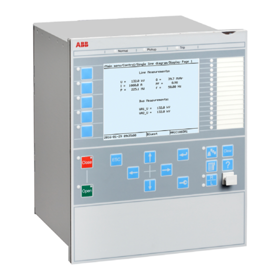
AMU0600442 v14 IEC13000239-3-en.vsd IEC13000239 V3 EN-US Figure 7: Local human-machine interface The LHMI of the IED contains the following elements: • Keypad • Display (LCD) • LED indicators • Communication port for PCM600 Line differential protection RED650 2.2 IEC Technical manual... -
Page 73: Keypad
The push-buttons are also used to acknowledge alarms, reset indications, provide help and switch between local and remote control mode. The keypad also contains programmable push-buttons that can be configured either as menu shortcut or control buttons. Line differential protection RED650 2.2 IEC Technical manual... - Page 74 LHMI keypad with object control, navigation and command push- buttons and RJ-45 communication port 1...5 Function button Close Open Escape Left Down Right Enter Remote/Local Uplink LED Not in use Multipage Menu Line differential protection RED650 2.2 IEC Technical manual...
-
Page 75: Display
320 x 240 pixels. The character size can vary. The amount of characters and rows fitting the view depends on the character size and the view that is shown. The display view is divided into four basic areas. Line differential protection RED650 2.2 IEC Technical manual... - Page 76 If text, pictures or other items do not fit in the display, a vertical scroll bar appears on the right. The text in content area is truncated from the beginning if it does not fit in the display horizontally. Truncation is indicated with three dots. Line differential protection RED650 2.2 IEC Technical manual...
- Page 77 Each function button has a LED indication that can be used as a feedback signal for the function button control action. The LED is connected to the required signal with PCM600. Line differential protection RED650 2.2 IEC Technical manual...
-
Page 78: Leds
Pressing the ESC button clears the panel from the display. Both panels have a dynamic width that depends on the label string length. 5.5.1.3 LEDs AMU0600427 v13 The LHMI includes three status LEDs above the display: Ready, Start and Trip. Line differential protection RED650 2.2 IEC Technical manual... - Page 79 OPENCLOSE_LED function block. For instance, OPENCLOSE_LED can be connected to a circuit breaker to indicate the breaker open/close status on the LEDs. IEC16000076-1-en.vsd IEC16000076 V1 EN-US Figure 13: OPENCLOSE_LED connected to SXCBR Line differential protection RED650 2.2 IEC Technical manual...
-
Page 80: Led Configuration Alternatives
BxRBDR binary input function block using the PCM600, and configuring the setting to Off, Start or Trip for that particular signal. 5.5.2.3 Indication LEDs Operating modes GUID-B67F1ED3-900B-4D34-8EEB-A3005999CE50 v4 Collecting mode Line differential protection RED650 2.2 IEC Technical manual... - Page 81 • Automatic reset • The automatic reset can only be performed for LED indications defined for re-starting mode with the latched sequence type 6 (LatchedReset-S). Line differential protection RED650 2.2 IEC Technical manual...
- Page 82 This sequence follows the corresponding input signals all the time with a steady light. It does not react on acknowledgment or reset. Every LED is independent of the other LEDs in its operation. Line differential protection RED650 2.2 IEC Technical manual...
- Page 83 If the signal is still present after acknowledgment it gets a steady light. Activating signal Acknow. en01000231.vsd IEC01000231 V1 EN-US Figure 17: Operating Sequence 3 LatchedAck-F-S GUID-CC607709-5344-4C88-AA97-6395FD335E55 v5 Line differential protection RED650 2.2 IEC Technical manual...
- Page 84 19. Activating signal GREEN Activating signal YELLOW Activating signal RED Acknow. IEC09000314-1-en.vsd IEC09000314 V1 EN-US Figure 19: Operating sequence 3, three colors involved, alternative 1 GUID-071B9EB5-A1D2-49C5-9458-4D21B7E068BE v3 Line differential protection RED650 2.2 IEC Technical manual...
- Page 85 That means if an indication with higher priority has reset while an indication with lower priority still is active at the time of reset, the LED will change color according to figure22. Line differential protection RED650 2.2 IEC Technical manual...
- Page 86 LEDs set for sequence 6 are completely independent in its operation of LEDs set for other sequences. Timing diagram for sequence 6 SEMOD56072-86 v4 Figure shows the timing diagram for two indications within one disturbance. Line differential protection RED650 2.2 IEC Technical manual...
- Page 87 Disturbance Disturbance tRestart tRestart Activating signal 1 Activating signal 2 LED 1 LED 2 Automatic reset Manual reset IEC01000240_2_en.vsd IEC01000240 V2 EN-US Figure 24: Operating sequence 6 (LatchedReset-S), two different disturbances Line differential protection RED650 2.2 IEC Technical manual...
- Page 88 Disturbance tRestart Activating signal 1 Activating signal 2 LED 1 LED 2 Automatic reset Manual reset IEC01000242_2_en.vsd IEC01000242 V2 EN-US Figure 26: Operating sequence 6 (LatchedReset-S), manual reset Line differential protection RED650 2.2 IEC Technical manual...
-
Page 89: Function Keys
In this mode the output toggles each time the function key has been pressed for more than 500ms. Note that the input attribute is reset each time the function block executes. The function block execution is marked with a dotted line below. Line differential protection RED650 2.2 IEC Technical manual... - Page 90 It has been implemented this way for safety reasons; the idea is that the function key LEDs should always reflect the actual status of any primary equipment monitored by these LEDs. Line differential protection RED650 2.2 IEC Technical manual...
-
Page 91: Section 6 Differential Protection
Protected zone Comm. Channel Comm. Channel Comm. Channel IEC05000042_2_en.vsd IEC05000042 V2 EN-US Figure 30: Example of application on a three-terminal line with an in-line power transformer in the protection zone Line differential protection RED650 2.2 IEC Technical manual... -
Page 92: Analog Signal Transfer For Line Differential Protection
Operation for the differential function is set to Off. For line differential protection we recommend that all feeder ends use the same version of RED650 or RED670 and the line data communication module LDCM. The line differential protection in the latest version of RED650 is compatible with older versions of RED670 and RED650. -
Page 93: Function Block
IEC06000254 V3 EN-US Figure 31: LT3CPDIF function block M12591-3 v4 LDLPSCH CTFAIL TRIP OUTSERV TRL1 BLOCK TRL2 TRL3 TRLOCAL TRLOCL1 TRLOCL2 TRLOCL3 TRREMOTE DIFLBLKD IEC13000302-1-en.vsd IEC13000302 V1 EN-US Figure 32: LDLPSCH function block Line differential protection RED650 2.2 IEC Technical manual... -
Page 94: Signals
An open CT was detected OPENCTAL BOOLEAN Open CT Alarm output signal. Issued after a delay ... IDL1 REAL Instantaneous differential current, phase L1 IDL2 REAL Instantaneous differential current, phase L2 Table continues on next page Line differential protection RED650 2.2 IEC Technical manual... - Page 95 Trip from local differential function in phase L2 TRLOCL3 BOOLEAN Trip from local differential function in phase L3 TRREMOTE BOOLEAN Trip from remote differential function DIFLBLKD BOOLEAN Local line differential function blocked Line differential protection RED650 2.2 IEC Technical manual...
-
Page 96: Settings
L.T. inv. IEC Norm. inv. IEC Very inv. IEC inv. IEC Ext. inv. IEC S.T. inv. IEC L.T. inv. IEC Def. Time Programmable RI type RD type Table continues on next page Line differential protection RED650 2.2 IEC Technical manual... - Page 97 Selection of one of the Global Base Value groups NoOfUsedCTs Total number of 3-Ph CT sets connected to diff protection ZerSeqCurSubtr Off/On for elimination of zero seq. from diff. and bias curr Table continues on next page Line differential protection RED650 2.2 IEC Technical manual...
- Page 98 Name Values (Range) Unit Step Default Description Operation Operation Off / On TestModeSet Test mode On/Off ReleaseLocal Block all Block all Release of local terminal for trip under Release local test mode Line differential protection RED650 2.2 IEC Technical manual...
-
Page 99: Monitored Data
The local currents are fed to the IED via the analog input modules and then they pass the analog-to-digital converter, as shown in Figure 33. Line differential protection RED650 2.2 IEC Technical manual... - Page 100 IED, they are processed in the Line Differential Communication Module (LDCM) where they are time-coordinated with the local current samples, and interpolated in order to be comparable with the local samples. Line differential protection RED650 2.2 IEC Technical manual...
- Page 101 There is also an unrestrained high differential current setting that can be used for fast tripping of internal faults with very high currents. This unrestrained protection is phase-segregated, that is, it is known which phase(s) require a trip command. Line differential protection RED650 2.2 IEC Technical manual...
- Page 102 5 harmonic analysis of the three instantaneous differential currents. Occurrence of these harmonics over a level that is set separately for each one blocks tripping action from the biased slope evaluation. Line differential protection RED650 2.2 IEC Technical manual...
- Page 103 In reality, the angle will usually be greater than zero, and this because of the possible different negative sequence impedance angles on both sides as seen from the fault location. Line differential protection RED650 2.2 IEC Technical manual...
- Page 104 With reference to Figure 33, the outputs from the three analysis blocks are fed to the output logic. Figure shows a simplified block diagram of this output logic where only trip commands and no alarm signals are shown for simplicity. Line differential protection RED650 2.2 IEC Technical manual...
- Page 105 CrossBlockEn = OFF. If CrossBlockEn = ON, then all phases with their start signals set, must be free of their respective harmonic block signals; otherwise no trip command is issued. Otherwise it is blocked as long Line differential protection RED650 2.2 IEC Technical manual...
- Page 106 Note that the subtraction of the charging current is limited to a value specified by IdMin. Observe as well that IdMin must always be set at least 25 % - 50 % above the value of charging currents. Line differential protection RED650 2.2 IEC Technical manual...
-
Page 107: Time Synchronization
Δt between the clocks in A and B is then possible to do with equation and equation 3, which are only valid under the condition that the send and receive times are equal. Line differential protection RED650 2.2 IEC Technical manual... -
Page 108: Analog Signal Communication For Line Differential Protection
IED where the evaluation is made and trip signals are sent to the remote ends when needed. In this system, a 64 kbit/s communication channel is only needed between the master, and each one of the slave IEDs. Line differential protection RED650 2.2 IEC Technical manual... - Page 109 Redundant communication channels SEMOD52415-25 v4 With redundant communication channels, as shown in figure 39, both channels are in operation continuously but with one of them favoured as a primary channel. Line differential protection RED650 2.2 IEC Technical manual...
-
Page 110: Open Ct Detection Feature
CTs are accidentally interrupted at precisely the same time, this feature cannot operate. Line differential protection generates a trip signal if the false differential current is sufficiently high. An open CT circuit is typically detected in 12–14 ms, Line differential protection RED650 2.2 IEC Technical manual... - Page 111 CT secondary circuit. The algorithm clearly indicates the IED side, CT input and phase in which an open CT condition has been detected. These indications are provided via the following outputs from the Line differential protection function: Line differential protection RED650 2.2 IEC Technical manual...
-
Page 112: Binary Signal Transfer
The task of LDLPSCH is to transfer the signals via LDCM between IEDs in the protection zone. Once LDLPSCH receives a block or trip signal from one IED, this block or trip signal is transferred to other IEDs by LDLPSCH function. Line differential protection RED650 2.2 IEC Technical manual... - Page 113 When LDLPSCH receives the trip signal from local IED (or remote IED), this trip signal is transferred to remote IEDs (or local IED) in the protection zone. Figure shows a simplified block diagram which illustrates trip signal handling by LDLPSCH. Line differential protection RED650 2.2 IEC Technical manual...
- Page 114 Signal from LDCM Test mode from remote terminal 2 testModeRemoteTerm3 Signal from LDCM Test mode from remote terminal 3 blockRemoteTerm1 Signal from LDCM Block from remote terminal 1 Table continues on next page Line differential protection RED650 2.2 IEC Technical manual...
-
Page 115: Technical Data
±1.0% of I at I ≤ I ±1.0% of I at I > I SlopeSection2 (10.0-50.0)% SlopeSection3 (30.0-100.0)% EndSection 1 (20–150)% of IBase IBase EndSection 2 (100–1000)% of Table continues on next page Line differential protection RED650 2.2 IEC Technical manual... - Page 116 The fault is performed by increasing one phase current to double on one side and decreasing same phase current to zero on the other side. Line differential protection RED650 2.2 IEC Technical manual...
-
Page 117: Section 7 Impedance Protection
The operation of the phase-selection element is primarily based on current change criteria (i.e. delta quantities), with significantly increased dependability. There is also a phase selection criterion operating in parallel which bases its operation only on voltage and current phasors. Line differential protection RED650 2.2 IEC Technical manual... -
Page 118: Function Block
STL1ZRV STL2ZRV STL3ZRV STNDZRV STND STNDL1 STNDL2 STNDL3 STNDPE STFWL1 STFWL2 STFWL3 STFWPE STRVL1 STRVL2 STRVL3 STRVP E STFW1PH STFW2PH STFW3PH STPE STPP IEC11000433-5-en.vsdx IEC11000433 V5 EN-US Figure 42: ZMFPDIS function block Line differential protection RED650 2.2 IEC Technical manual... -
Page 119: Signals
Trip in any phase or phases from zone 1 - forward direction TRL1Z1 BOOLEAN Trip in phase L1 from zone 1 - forward direction TRL2Z1 BOOLEAN Trip in phase L2 from zone 1 - forward direction Table continues on next page Line differential protection RED650 2.2 IEC Technical manual... - Page 120 Start in phase L1 from zone RV - reverse direction STL2ZRV BOOLEAN Start in phase L2 from zone RV - reverse direction STL3ZRV BOOLEAN Start in phase L3 from zone RV - reverse direction Table continues on next page Line differential protection RED650 2.2 IEC Technical manual...
-
Page 121: Settings
Dead band & 5s Cyclic Dead band & 30s Cyclic Dead band & 1min Cyclic ZAngDbRepInt 1 - 100000 Type Cycl: Report interval (s), Db: In % of range, Int Db: In %s Line differential protection RED650 2.2 IEC Technical manual... -
Page 122: Monitored Data
Resistance in phase L3 REAL Reactance in phase L3 L12R REAL Resistance in phase L1- L12X REAL Reactance in phase L1- L23R REAL Resistance in phase L2- Table continues on next page Line differential protection RED650 2.2 IEC Technical manual... -
Page 123: Operation Principle
GUID-2432C04F-62E4-4817-9900-C830306FB4B0 v3 Settings, input and output names are sometimes mentioned in the following text without its zone suffix (i.e. BLKZx instead of BLKZ3) when the description is equally valid for all zones. Line differential protection RED650 2.2 IEC Technical manual... -
Page 124: Filtering
So, a setting (CVTtype) is introduced in order to inform the algorithm about the type of CVT applied and Line differential protection RED650 2.2 IEC Technical manual... -
Page 125: Phase-Selection Element
Measurement in two phase-to-earth loops at the same time is associated with so-called simultaneous faults: two earth faults at the same time, one each on the two circuits of a double line, or when the Line differential protection RED650 2.2 IEC Technical manual... -
Page 126: Directional Criteria
L1 and L2 (L2 lagging L1). PolL1L2 is the current difference between phase L1 and L2 (L2 lagging L1). L1L2 The corresponding reverse directional sectors range from 165 to -60 degrees. Line differential protection RED650 2.2 IEC Technical manual... -
Page 127: Fuse Failure
Zone 1 has individual positive sequence impedance settings for phase-to-phase and phase-to-earth (X1PPZ1, R1PPZ1 and X1PEZ1, R1PEZ1). For the other zones, the positive sequence impedance reach is common for phase-to-phase and phase-to- earth (X1Zx, R1Zx). Line differential protection RED650 2.2 IEC Technical manual... - Page 128 Section 7 1MRK 505 394-UEN A Impedance protection (Ohm/phase) RFPPZx R1Zx RFPPZx X1Zx (Ohm/phase) RFPPZx RFPPZx X1Zx RFPPZx R1Zx RFPPZx IEC11000416-2-en.vsdx IEC11000416 V2 EN-US Figure 44: ZMFPDIS Characteristic for phase-to-phase measuring, ohm/loop domain Line differential protection RED650 2.2 IEC Technical manual...
- Page 129 (arc) may be divided into parts like for three-phase or phase-to-phase faults. The R1Zx + jX1Zx represent the positive sequence impedance from the measuring point to the fault location. Line differential protection RED650 2.2 IEC Technical manual...
- Page 130 Zones 3 to 5 can be selected to be either forward or reverse with positive sequence polarized mho characteristic; alternatively self polarized offset mho characteristics. The operating characteristic is in accordance to figure where zone 5 is selected offset mho. Line differential protection RED650 2.2 IEC Technical manual...
- Page 131 Forward or Reverse, directional lines are introduced. Information about the directional lines is given from the directional element. Basic Mho and offset Mho characteristics with different mode settings are indicated in figure 48. Line differential protection RED650 2.2 IEC Technical manual...
- Page 132 The mho algorithm is based on the phase comparison of an operating phasor and a polarizing phasor. When the operating phasor leads the reference polarizing phasor by 90 degrees or more, the function operates and gives a trip output. Phase-to-phase fault SEMOD154224-240 v2 GUID-D162893C-918A-4DDA-AAC2-0D0A814D85C1 v1 Line differential protection RED650 2.2 IEC Technical manual...
- Page 133 (x=2-5 and RV) X1Zx is the positive sequence reactance reach for zone x (x=2-5 and RV) is the polarizing voltage Operation occurs if 90°≤β≤270° Line differential protection RED650 2.2 IEC Technical manual...
- Page 134 The angle β for L1 to L2 fault can be defined according to equation below. (Equation 9) IECEQUATION15008 V2 EN-US Line differential protection RED650 2.2 IEC Technical manual...
- Page 135 Compensation for earth return path for faults involving earth is done by setting the positive and zero sequence impedance of the line. It is known that the ground compensation factor K Line differential protection RED650 2.2 IEC Technical manual...
- Page 136 L1 is the complex positive sequence impedance of the line in Ω/phase for phase-to-earth fault in zone direction is the polarizing voltage for phase L1 Line differential protection RED650 2.2 IEC Technical manual...
- Page 137 52. The angle will be 90° for fault location on the boundary of the circle. (Equation 12) IECEQUATION15022 V2 EN-US Line differential protection RED650 2.2 IEC Technical manual...
-
Page 138: Load Encroachment
The IED has a built in feature which shapes the characteristic according to the characteristic shown in figure 53. The load encroachment algorithm will increase Line differential protection RED650 2.2 IEC Technical manual... -
Page 139: Simplified Logic Schemes
(RV) signals. The internal input 'IN present' is activated if the residual current (3I0) exceeds 10% of the maximum phase current magnitude and at the same time is above 5% of [1] RLdRv=RLdRvFactor*RLdFw Line differential protection RED650 2.2 IEC Technical manual... - Page 140 FW(Ln & LmLn) FW(Ln & LmLn) RV(Ln & LmLn) DirModeZ3-5 TRUE (1) FW(Ln & LmLn) Forward RV(Ln & LmLn) Reverse IEC12000137-2-en.vsd IEC12000137 V3 EN-US Figure 54: Connection of directional signals to Zones Line differential protection RED650 2.2 IEC Technical manual...
- Page 141 L1Zx ZML3Zx PHSL3 DIRL3Zx ZML1L2Zx L2Zx PHSL1L2 DIRL1L2Zx ZML2L3Zx PHSL2L3 L3Zx DIRL2L3Zx ZML3L1Zx PHSL3L1 DIRL3L1Zx PPZx RELCNDZx L1L2 Integer to Bool L2L3 NDZx L1L3 IEC12000140-2-en.vsdx IEC12000140 V2 EN-US Figure 55: Intermediate logic Line differential protection RED650 2.2 IEC Technical manual...
- Page 142 No Links Phase Selection 1st starting zone FALSE (0) External start LNKZ2 LNKZx TimerLinksZx = LNKZ4 LoopLink & ZoneLink LNKZ5 EXTNST IEC12000139-4-en.vsdx IEC12000139 V4 EN-US Figure 56: Logic for linking of timers Line differential protection RED650 2.2 IEC Technical manual...
- Page 143 BLKZx TRL3Zx 15 ms L1Zx STL1Zx 15 ms L2Zx STL2Zx 15 ms STL3Zx PPZx 15 ms PEZx STARTZx 15 ms NDZx STNDZx IEC12000138-2-en.vsd IEC12000138 V2 EN-US Figure 57: Start and trip outputs Line differential protection RED650 2.2 IEC Technical manual...
- Page 144 1MRK 505 394-UEN A Impedance protection 15 ms STPE 15 ms 15 ms PHSL1L2 15 ms 15 ms STPP BLOCK STARTND VTSZ STPHS IEC12000133-2-en.vsd IEC12000133 V2 EN-US Figure 58: Additional start outputs 1 Line differential protection RED650 2.2 IEC Technical manual...
- Page 145 PHSL1 RVL1 15 ms RVL2 RVL3 15 ms STRVL2 PHSL1L2 RVL1L2 PHSL2L3 15 ms RVL2L3 STRVL3 RVL3L1 STRVPE IN present BLOCK VTSZ IEC12000141-2-en.vsdx IEC12000141 V2 EN-US Figure 60: Additional start outputs 3 Line differential protection RED650 2.2 IEC Technical manual...
-
Page 146: Measurement
Overfunction, when the measured quantity exceeds the High limit (XHiLim) or High-high limit (XHiHiLim) pre-set values • Underfunction, when the measured quantity decreases under the Low limit (XLowLim) or Low-low limit (XLowLowLim) pre-set values. X_RANGE is illustrated in figure 61. Line differential protection RED650 2.2 IEC Technical manual... - Page 147 Amplitude Deadband and 1min cyclic Cyclic reporting SEMOD54417-158 v3 The cyclic reporting of measured value is performed according to chosen setting (XRepTyp). The measuring channel reports the value independent of amplitude or integral dead-band reporting. Line differential protection RED650 2.2 IEC Technical manual...
- Page 148 The picture is simplified: the process is not continuous but the values are evaluated with a time interval of one execution cycle from each other. Line differential protection RED650 2.2 IEC Technical manual...
- Page 149 (as well as for the values Y3, Y4 and Y5). The integral dead-band supervision is particularly suitable for monitoring signals with small variations that can last for relatively long periods. Line differential protection RED650 2.2 IEC Technical manual...
- Page 150 2% of IBase, the resistance and reactance of the impedance are forced to 99 999 ohm, corresponding to a magnitude at 141419 (99 999*√2) ohm and an angle at 45 degree. Line differential protection RED650 2.2 IEC Technical manual...
-
Page 151: Technical Data
±0.2% of set value or ±35 ms whichever and Ph-Ph operation is greater Operate time 24 ms typically, IEC 60255-121 Reset time at 0.1 to 2 x Zreach Min. = 20 ms Max. = 35 ms Line differential protection RED650 2.2 IEC Technical manual... -
Page 152: Power Swing Detection Zmrpsb
Table 49: ZMRPSB Input signals Name Type Default Description GROUP Group signal for current input SIGNAL GROUP Group signal for voltage input SIGNAL BLOCK BOOLEAN Block of function Table continues on next page Line differential protection RED650 2.2 IEC Technical manual... -
Page 153: Settings
Outer resistive load boundary, forward ArgLd 5 - 70 Load angle determining load impedance area RLdOutRv 0.01 - 3000.00 Ohm/p 0.01 30.00 Outer resistive load boundary, reverse Table continues on next page Line differential protection RED650 2.2 IEC Technical manual... -
Page 154: Operation Principle
The impedance and the characteristic passing times are measured in all three phases separately. One-out-of-three or two-out-of-three operating modes can be selected according to the specific system operating conditions. Line differential protection RED650 2.2 IEC Technical manual... -
Page 155: Resistive Reach In Forward Direction
To avoid load encroachment, the resistive reach is limited in forward direction by setting the parameter RLdOutFw which is the outer resistive load boundary value while the inner resistive boundary is calculated according to equation 15. Line differential protection RED650 2.2 IEC Technical manual... -
Page 156: Resistive Reach In Reverse Direction
The inner resistive characteristic in the second quadrant outside the load encroachment part corresponds to the setting parameter R1FInRv for the inner boundary. The outer boundary is internally calculated as the sum of DRv+R1FInRv. Line differential protection RED650 2.2 IEC Technical manual... -
Page 157: Reactive Reach In Forward And Reverse Direction
The tP2 timer become activated for the detection of the consecutive swings, if the measured impedance exit the operate area and returns within the time delay, set on the tW waiting timer. The upper part Line differential protection RED650 2.2 IEC Technical manual... - Page 158 Detection of power swing in phase L1 DET-L1 DET-L2 DET1of3 - int. >1 DET-L3 & DET2of3 - int. >1 & & IEC01000057-2-en.vsd IEC01000057-TIFF V2 EN-US Figure 68: Detection of power swing for 1-of-3 and 2-of-3 operating mode Line differential protection RED650 2.2 IEC Technical manual...
-
Page 159: Operating And Inhibit Conditions
OperationLdCh = Off, but notice that the DFw and DRv will still be calculated from RLdOutFw and RLdOutRv. The characteristic will in this case be only quadrilateral. There are four different ways to form the internal INHIBIT signal: Line differential protection RED650 2.2 IEC Technical manual... -
Page 160: Technical Data
±1.0% of I Automatic switch onto fault logic ZCVPSOF SEMOD153633-1 v3 7.3.1 Identification SEMOD155890-2 v4 Function description IEC 61850 IEC 60617 ANSI/IEEE C37.2 identification identification device number Automatic switch onto fault logic ZCVPSOF Line differential protection RED650 2.2 IEC Technical manual... -
Page 161: Functionality
SIGNAL BLOCK BOOLEAN Block of function START_DLYD BOOLEAN Start from function to be accelerated with delay by SOTF BOOLEAN External enabling of SOTF ZACC BOOLEAN Distance zone to be accelerated by SOTF Line differential protection RED650 2.2 IEC Technical manual... -
Page 162: Settings
PID-3875-MONITOREDDATA v7 Table 59: ZCVPSOF Monitored data Name Type Values (Range) Unit Description REAL Current in phase L1 REAL Current in phase L2 REAL Current in phase L3 Table continues on next page Line differential protection RED650 2.2 IEC Technical manual... -
Page 163: Operation Principle
Mode = UILevel; TRIP is released if UILevel detector is activated • Mode = UILvl&Imp; TRIP is released based either on the impedance- measured criteria or UILevel detection The ZCVPSOF function can be blocked by activating the input BLOCK. Line differential protection RED650 2.2 IEC Technical manual... -
Page 164: Technical Data
Delay time for activation of dead line detection (0.000-60.000) s ±0.2% or ±20 ms whichever is greater Drop-off delay time of switch onto fault function (0.000-60.000) s ±0.2% or ±30 ms whichever is greater Line differential protection RED650 2.2 IEC Technical manual... -
Page 165: Section 8 Current Protection
8.1.4 Signals IP11433-1 v2 PID-6914-INPUTSIGNALS v3 Table 61: PHPIOC Input signals Name Type Default Description GROUP Three phase current SIGNAL BLOCK BOOLEAN Block of function ENMULT BOOLEAN Enable current start value multiplier Line differential protection RED650 2.2 IEC Technical manual... -
Page 166: Settings
Value groups 8.1.6 Monitored data PID-6914-MONITOREDDATA v3 Table 66: PHPIOC Monitored data Name Type Values (Range) Unit Description REAL Current in phase L1 REAL Current in phase L2 REAL Current in phase L3 Line differential protection RED650 2.2 IEC Technical manual... -
Page 167: Operation Principle
Figure 73. IP>>Max IP>>_used IP>> IP>>Min IEC17000016-1-en.vsdx IEC17000016 V1 EN-US Figure 73: Logic for limitation of used operation current value PHPIOC can be blocked using the binary input BLOCK. Line differential protection RED650 2.2 IEC Technical manual... -
Page 168: Technical Data
Directional phase overcurrent protection, four steps (OC4PTOC) has an inverse or definite time delay for each step. All IEC and ANSI inverse time characteristics are available together with an optional user defined time characteristic. Line differential protection RED650 2.2 IEC Technical manual... -
Page 169: Function Block
TR4L3 START STL1 STL2 STL3 ST1L1 ST1L2 ST1L3 ST2L1 ST2L2 ST2L3 ST3L1 ST3L2 ST3L3 ST4L1 ST4L2 ST4L3 ST2NDHRM DIRL1 DIRL2 DIRL3 STDI RCND IEC06000187-4-en.vsdx IEC06000187 V4 EN-US Figure 74: OC4PTOC function block Line differential protection RED650 2.2 IEC Technical manual... -
Page 170: Signals
Trip signal from step2 phase L2 TR2L3 BOOLEAN Trip signal from step2 phase L3 TR3L1 BOOLEAN Trip signal from step3 phase L1 TR3L2 BOOLEAN Trip signal from step3 phase L2 Table continues on next page Line differential protection RED650 2.2 IEC Technical manual... -
Page 171: Settings
Values (Range) Unit Step Default Description Operation Operation Off / On AngleRCA 40 - 65 Relay characteristic angle (RCA) AngleROA 40 - 89 Relay operation angle (ROA) Table continues on next page Line differential protection RED650 2.2 IEC Technical manual... - Page 172 1 I1Mult 1.0 - 10.0 Multiplier for current operate level for step 1 DirMode2 Non-directional Directional mode of step 2 (off, nodir, Non-directional forward, reverse) Forward Reverse Table continues on next page Line differential protection RED650 2.2 IEC Technical manual...
- Page 173 Operating phase current level for step 3 in % of IBase 0.000 - 60.000 0.001 0.800 Def time delay or add time delay for inverse char of step 3 Table continues on next page Line differential protection RED650 2.2 IEC Technical manual...
- Page 174 5 - 2500 Minimum used operating phase current level for step 1 in % of IBase, if I1> is less than I1>Min then I1> is set to I1>Min Table continues on next page Line differential protection RED650 2.2 IEC Technical manual...
- Page 175 0.005 - 100.000 0.001 13.500 Parameter TR for customer programmable curve for step 2 tCRCrv2 0.1 - 10.0 Parameter CR for customer programmable curve for step 2 Table continues on next page Line differential protection RED650 2.2 IEC Technical manual...
- Page 176 0.00 - 20.00 0.01 0.00 Parameter B for customer programmable curve for step 4 tCCrv4 0.1 - 10.0 Parameter C for customer programmable curve for step 4 Table continues on next page Line differential protection RED650 2.2 IEC Technical manual...
-
Page 177: Monitored Data
For each step x , where x is step 1, 2, 3 and 4, an operation mode is set by DirModex: Off/Non-directional/Forward/Reverse. The protection design can be divided into four parts: Line differential protection RED650 2.2 IEC Technical manual... - Page 178 If the RMS option is selected, then the true RMS value is used. The true RMS value includes the contribution from the current DC component as well as from the higher current harmonic in addition to the fundamental frequency component. Line differential protection RED650 2.2 IEC Technical manual...
- Page 179 L dirL L (Equation 19) EQUATION1451 V1 EN-US Phase-earth short circuit: refL dirL (Equation 20) EQUATION1452 V1 EN-US refL dirL (Equation 21) EQUATION1453 V1 EN-US refL dirL (Equation 22) EQUATION1454 V1 EN-US Line differential protection RED650 2.2 IEC Technical manual...
- Page 180 The directional setting is given as a characteristic angle AngleRCA for the function and an angle window ROADir. Reverse Forward en05000745.vsd IEC05000745 V1 EN-US Figure 76: Directional characteristic of the phase overcurrent protection Line differential protection RED650 2.2 IEC Technical manual...
- Page 181 The possibilities for inverse time characteristics are described in section "Inverse characteristics". Characteristx=DefTime a>b Ix> BLKSTx BLOCK Inverse Characteristx=Inverse STAGEx_DIR_Int DirModex=Off DirModex=Non-directional DirModex=Forward FORWARD_Int DirModex=Reverse REVERSE_Int IEC12000008.vsd IEC12000008.vsd IEC12000008 V2 EN-US Figure 77: Simplified logic diagram for OC4PTOC Line differential protection RED650 2.2 IEC Technical manual...
- Page 182 Ix>Min, the limits are swapped. The principle of the limitation is shown in Figure 79. Ix>Max Ix>_used Ix> Ix>Min IEC17000018-1-en.vsdx IEC17000018 V1 EN-US Figure 79: Logic for limitation of used operation current value Line differential protection RED650 2.2 IEC Technical manual...
- Page 183 2ndHarmStab setting, any of the four overcurrent stages can be selectively blocked by the parameter HarmBlockx setting. When the 2nd harmonic restraint feature is active, the OC4PTOC function output signal ST2NDHRM will be set to the logical value one. Line differential protection RED650 2.2 IEC Technical manual...
-
Page 184: Technical Data
Reset time, start non-directional at 10 x I Min. = 20 ms Max. = 35 ms Critical impulse time 10 ms typically at 0 to 2 x I Impulse margin time 15 ms typically Line differential protection RED650 2.2 IEC Technical manual... -
Page 185: Instantaneous Residual Overcurrent Protection Efpioc
PID-6915-INPUTSIGNALS v4 Table 76: EFPIOC Input signals Name Type Default Description GROUP Three phase currents SIGNAL BLOCK BOOLEAN Block of function BLKAR BOOLEAN Block input for auto reclose ENMULT BOOLEAN Enable current multiplier Line differential protection RED650 2.2 IEC Technical manual... -
Page 186: Settings
The sampled analog residual currents are pre-processed in a discrete Fourier filter (DFT) block. From the fundamental frequency components of the residual current, as well as from the sample values the equivalent RMS value is derived. This Line differential protection RED650 2.2 IEC Technical manual... -
Page 187: Technical Data
Operate time at 0 to 2 x I Min. = 15 ms Max. = 25 ms Reset time at 2 x I to 0 Min. = 15 ms Max. = 25 ms Table continues on next page Line differential protection RED650 2.2 IEC Technical manual... -
Page 188: Directional Residual Overcurrent Protection, Four Steps Ef4Ptoc
A second harmonic blocking can be set individually for each step. Directional operation can be combined together with the corresponding communication logic in permissive or blocking teleprotection scheme. The current reversal and weak-end infeed functionality are available as well. Line differential protection RED650 2.2 IEC Technical manual... -
Page 189: Function Block
When activated, the current multiplier is in use for step1 ENMULT2 BOOLEAN When activated, the current multiplier is in use for step2 ENMULT3 BOOLEAN When activated, the current multiplier is in use for step3 Table continues on next page Line differential protection RED650 2.2 IEC Technical manual... -
Page 190: Settings
-180 - 180 Relay Characteristic Angle (RCA) polMethod Voltage Voltage Type of polarization Current Dual UPolMin 1 - 100 Minimum voltage level for polarization in % of UBase Table continues on next page Line differential protection RED650 2.2 IEC Technical manual... - Page 191 Pos / CB Command) tUnderTime 0.000 - 60.000 0.001 0.300 Time delay for under time DirMode1 Non-directional Directional mode of step 1 (Off, Non-dir, Non-directional Forward, Reverse) Forward Reverse Table continues on next page Line differential protection RED650 2.2 IEC Technical manual...
- Page 192 IEC L.T. inv. IEC Def. Time Reserved Programmable RI type RD type IN2> 1 - 2500 Residual current operate level for step 2 in % of IBase Table continues on next page Line differential protection RED650 2.2 IEC Technical manual...
- Page 193 3 HarmBlock3 Enable block of step 3 from harmonic restrain DirMode4 Non-directional Directional mode of step 4 (Off, Non-dir, Non-directional Forward, Reverse) Forward Reverse Table continues on next page Line differential protection RED650 2.2 IEC Technical manual...
- Page 194 Param P for customized inverse trip time curve for step 1 tACrv1 0.005 - 200.000 0.001 13.500 Param A for customized inverse trip time curve for step 1 Table continues on next page Line differential protection RED650 2.2 IEC Technical manual...
- Page 195 0.000 - 60.000 0.001 0.020 Reset time delay for step 3 tPCrv3 0.005 - 3.000 0.001 1.000 Param P for customized inverse trip time curve for step 3 Table continues on next page Line differential protection RED650 2.2 IEC Technical manual...
- Page 196 Choice of measurand for directional Neg seq current SeqTypeIPol Zero seq Zero seq Choice of measurand for polarizing Neg seq current SeqTypeUPol Zero seq Zero seq Choice of measurand for polarizing Neg seq voltage Line differential protection RED650 2.2 IEC Technical manual...
-
Page 197: Monitored Data
(when a dedicated CT input of the IED is connected in PCM600 to the fourth analog input of the pre-processing block connected to EF4PTOC function input I3P). This dedicated IED CT input can be, for example, connected to: Line differential protection RED650 2.2 IEC Technical manual... -
Page 198: Internal Polarizing
The function can be set to use voltage polarizing, current polarizing or dual polarizing. Voltage polarizing When voltage polarizing is selected, the protection will use the residual voltage as the polarizing quantity U3P. Line differential protection RED650 2.2 IEC Technical manual... - Page 199 EF4PTOC function input I3PPOL). This dedicated IED CT input is then typically connected to one single current transformer located between power system star point and earth (current transformer located in the star point of a star connected transformer winding). Line differential protection RED650 2.2 IEC Technical manual...
- Page 200 Then the phasor of the total polarizing voltage UTotPol will be used, together with the phasor of the operating current, to determine the direction of the earth fault (forward/reverse). Line differential protection RED650 2.2 IEC Technical manual...
-
Page 201: External Polarizing For Earth-Fault Function
8.4.7.7 Four residual overcurrent steps M13941-166 v8 Each overcurrent step uses operating quantity Iop (residual current) as the measuring quantity. Each of the four residual overcurrent steps has the following built-in facilities: Line differential protection RED650 2.2 IEC Technical manual... - Page 202 The principle of the limitation is shown in Figure 84. INx>Max INx>_used INx> INx>Min IEC17000017-1-en.vsdx IEC17000017 V1 EN-US Figure 84: Logic for limitation of used operation current value Simplified logic diagram for one residual overcurrent step is shown in Figure 85. Line differential protection RED650 2.2 IEC Technical manual...
-
Page 203: Directional Supervision Element With Integrated Directional Comparison Function
When polMethod = Voltage, UPol will be used as polarizing quantity. When polMethod = Current, IPol will be used as polarizing quantity. When polMethod = Dual, UPol + IPol · ZNPol will be used as polarizing quantity. Line differential protection RED650 2.2 IEC Technical manual... - Page 204 STRV=1 when operating quantity magnitude Iop x cos(φ - AngleRCA) is bigger than 60% of setting parameter IN>Dir and directional supervision element detects fault in reverse direction. Line differential protection RED650 2.2 IEC Technical manual...
-
Page 205: Second Harmonic Blocking Element
(defined by parameter 2ndHarmStab), output signal 2NDHARMD is set to logical value one and the harmonic restraining feature to the function block will be applicable. Blocking from the 2nd harmonic element activates if all of three criteria are satisfied: Line differential protection RED650 2.2 IEC Technical manual... - Page 206 UseStartValue (see condition 3 above). Simplified logic diagram for 2 harmonic blocking feature is shown in Figure 88. Line differential protection RED650 2.2 IEC Technical manual...
-
Page 207: Switch On To Fault Feature
StepForSOTF. The setting parameter ActivationSOTF can be set for activation of CB position open change, CB position closed change or CB close command. In case of a residual current start from step 2 or 3 (dependent on Line differential protection RED650 2.2 IEC Technical manual... - Page 208 ActUnderTime Close command STIN4 IEC06000643-5-en.vsdx IEC06000643 V5 EN-US Figure 89: Simplified logic diagram for SOTF and under-time features M13941-3 v6 Simplified logic diagram for the complete EF4PTOC function is shown in Figure Line differential protection RED650 2.2 IEC Technical manual...
-
Page 209: Technical Data
(0.000-60.000) s ±0.2% or ±35 ms whichever is greater Minimum operate time for inverse curves, (0.000 - 60.000) s ±0.2% or ±35 ms step 1-4 whichever is greater Table continues on next page Line differential protection RED650 2.2 IEC Technical manual... -
Page 210: Thermal Overload Protection, One Time Constant, Celsius/Fahrenheit Lcpttr/Lfpttr
Thermal overload protection, one time LFPTTR constant, Fahrenheit 8.5.2 Functionality M12020-4 v14 The increasing utilization of the power system closer to the thermal limits has generated a need of a thermal overload protection for power lines. Line differential protection RED650 2.2 IEC Technical manual... -
Page 211: Function Block
Current multiplyer used when THOL is for two or more lines AMBTEMP REAL Ambient temperature from external temperature sensor SENSFLT BOOLEAN Validity status of ambient temperature sensor RESET BOOLEAN Reset of internal thermal load counter Line differential protection RED650 2.2 IEC Technical manual... -
Page 212: Settings
0 - 400 The load current (in % of IBase) leading to TRef temperature IMult 1 - 5 Current multiplier when function is used for two or more lines Table continues on next page Line differential protection RED650 2.2 IEC Technical manual... - Page 213 External temperature sensor available DefaultAmbTemp -50 - 250 Deg F Ambient temperature used when AmbiSens is set to Off. DefaultTemp -50 - 600 Deg F Temperature raise above ambient temperature at startup Line differential protection RED650 2.2 IEC Technical manual...
-
Page 214: Monitored Data
LCPTTR/LFPTTR function. The temperature is displayed either in Celsius or Fahrenheit, depending on whether LCPTTR/LFPTTR function is selected. From the largest of the three-phase currents a final temperature is calculated according to the expression: Line differential protection RED650 2.2 IEC Technical manual... - Page 215 There is also a calculation of the present time to operate with the present current. This calculation is only performed if the final temperature is calculated to be above the operation temperature: Line differential protection RED650 2.2 IEC Technical manual...
- Page 216 The protection has a reset input: RESET. By activating this input the calculated temperature is reset to its default initial value. This is useful during testing when secondary injected current has given a calculated “false” temperature level. Line differential protection RED650 2.2 IEC Technical manual...
- Page 217 Lockout logic Actual Temp < Recl Temp BLOCK TTRIP Calculation of time to trip BLKTR TENRECL Calculation of time to reset of lockout IEC09000637-2-en.vsd IEC09000637 V2 EN-US Figure 92: Functional overview of LCPTTR/LFPTTR Line differential protection RED650 2.2 IEC Technical manual...
-
Page 218: Technical Data
Breaker failure protection (CCRBRF) ensures a fast backup tripping of the surrounding breakers in case the own breaker fails to open. CCRBRF can be current-based, contact-based or an adaptive combination of these two conditions. Line differential protection RED650 2.2 IEC Technical manual... -
Page 219: Function Block
Circuit breaker closed in phase L1 CBCLDL2 BOOLEAN Circuit breaker closed in phase L2 CBCLDL3 BOOLEAN Circuit breaker closed in phase L3 CBFLT BOOLEAN CB faulty, unable to trip. Back-up trip instantaneously Line differential protection RED650 2.2 IEC Technical manual... -
Page 220: Settings
0.000 - 60.000 0.001 0.150 Time delay of back-up trip t2MPh 0.000 - 60.000 0.001 0.150 Time delay of back-up trip at multi-phase start tPulse 0.000 - 60.000 0.001 0.200 Trip pulse duration Line differential protection RED650 2.2 IEC Technical manual... -
Page 221: Monitored Data
The re-trip function can be done with or without CB position check according to table 107. Line differential protection RED650 2.2 IEC Technical manual... - Page 222 • It is possible to have instantaneous back-up trip function if a signal is high if the circuit breaker is incapable to clear faults, for example at low gas pressure. Line differential protection RED650 2.2 IEC Technical manual...
- Page 223 Retrip Time Out L1 TRRETL2 phases tPulse TRRETL1 RetripMode No CBPos Check 30ms CB Pos Check CB Closed L1 CBFLT IEC09000978-4-en.vsd IEC09000978 V4 EN-US Figure 96: Simplified logic scheme of the retrip logic function Line differential protection RED650 2.2 IEC Technical manual...
-
Page 224: Technical Data
±1.0% of I at I > I Reset ratio > 95% Operate time for current detection 10 ms typically Reset time for current detection 15 ms maximum Table continues on next page Line differential protection RED650 2.2 IEC Technical manual... -
Page 225: Pole Discordance Protection Ccpdsc
The Pole discordance protection function (CCPDSC) operates based on information from auxiliary contacts of the circuit breaker for the three phases with additional criteria from unsymmetrical phase currents when required. Line differential protection RED650 2.2 IEC Technical manual... -
Page 226: Function Block
BOOLEAN Pole three closed indication from CB PID-3525-OUTPUTSIGNALS v8 Table 110: CCPDSC Output signals Name Type Description TRIP BOOLEAN Trip signal to CB START BOOLEAN Trip condition TRUE, waiting for time delay Line differential protection RED650 2.2 IEC Technical manual... -
Page 227: Settings
The detection of pole discordance can be made in two different ways. If the contact based function is used an external logic can be made by connecting the auxiliary contacts of the circuit breaker so that a pole discordance is indicated, see figure 99. Line differential protection RED650 2.2 IEC Technical manual... - Page 228 CurrUnsymLevel times the largest phase current the settable trip timer (tTrip) is started. The tTrip timer gives a trip signal after the set delay. The TRIP signal is a pulse 150 ms long. The current based pole discordance function can be Line differential protection RED650 2.2 IEC Technical manual...
- Page 229 It can be connected to the output signal 1PT1 on SMBRRECfunction block. If the autoreclosing function is an external device, then BLKDBYAR has to be connected to a binary input in the IED and this binary input Line differential protection RED650 2.2 IEC Technical manual...
-
Page 230: Pole Discordance Signaling From Circuit Breaker
(that is from auxiliary contacts of the close and open push buttons) or may be software connected to the outputs of other integrated functions (that is close command from a control function or a general trip from integrated protections). Line differential protection RED650 2.2 IEC Technical manual... -
Page 231: Technical Data
Function Range or value Accuracy IBase Operate current (0–100)% of ±1.0% of I Independent time delay (0.000-60.000) s ±0.2% or ± 30 ms whichever between trip condition and trip is greater signal Line differential protection RED650 2.2 IEC Technical manual... -
Page 233: Section 9 Voltage Protection
UV2PTUV has two voltage steps, each with inverse or definite time delay. It has a high reset ratio to allow settings close to the system service voltage. Line differential protection RED650 2.2 IEC Technical manual... -
Page 234: Function Block
Common trip signal from step2 TR2L1 BOOLEAN Trip signal from step2 phase L1 TR2L2 BOOLEAN Trip signal from step2 phase L2 TR2L3 BOOLEAN Trip signal from step2 phase L3 Table continues on next page Line differential protection RED650 2.2 IEC Technical manual... -
Page 235: Settings
Time delay of internal (low level) blocking for step 1 HystAbs1 0.0 - 50.0 Absolute hysteresis in % of UBase, step OperationStep2 Enable execution of step 2 Table continues on next page Line differential protection RED650 2.2 IEC Technical manual... - Page 236 Reset time delay used in IEC Definite Time curve step 2 ResetTypeCrv2 Instantaneous Instantaneous Selection of used IDMT reset curve type Frozen timer for step 2 Linearly decreased Table continues on next page Line differential protection RED650 2.2 IEC Technical manual...
-
Page 237: Monitored Data
To avoid an unwanted trip due to the disconnection of the related high-voltage equipment, a voltage-controlled blocking of the function is Line differential protection RED650 2.2 IEC Technical manual... -
Page 238: Measurement Principle
A • inverse curve B • customer programmable inverse curve The type A curve is described as: æ ö < - ç ÷ < è ø (Equation 37) EQUATION1431 V2 EN-US Line differential protection RED650 2.2 IEC Technical manual... - Page 239 > (Equation 40) EQUATION1435 V1 EN-US The lowest voltage is always used for the inverse time delay integration. The details of the different inverse time characteristics are shown in section "Inverse characteristics". Line differential protection RED650 2.2 IEC Technical manual...
- Page 240 See figure and figure 105. Line differential protection RED650 2.2 IEC Technical manual...
- Page 241 Frozen Timer Time Linearly Instantaneous decreased IEC05000010-4-en.vsd IEC05000010 V4 EN-US Figure 104: Voltage profile not causing a reset of the START signal for step 1, and inverse time delay at different reset types Line differential protection RED650 2.2 IEC Technical manual...
- Page 242 106. Detailed information about individual stage reset/operation behavior is shown in figure and figure respectively. Note that by setting tResetn = 0.0s, instantaneous reset of the definite time delayed stage is ensured. Line differential protection RED650 2.2 IEC Technical manual...
- Page 243 Voltage protection tReset1 a<b U1< IEC09000785-3-en.vsd IEC09000785 V3 EN-US Figure 106: Logic diagram for step 1, DT operation U1< tReset1 IEC10000039-3-en.vsd IEC10000039 V3 EN-US Figure 107: Example for Definite Time Delay stage1 reset Line differential protection RED650 2.2 IEC Technical manual...
-
Page 244: Blocking
The event will START both the under voltage function and the blocking function, as seen in figure 109. The delay of the blocking function must be set less than the time delay of under voltage function. Line differential protection RED650 2.2 IEC Technical manual... -
Page 245: Design
A special logic is included to achieve the 1 out of 3, 2 out of 3 and 3 out of 3 criteria to fulfill the START condition. The design of Two step undervoltage protection UV2PTUV is schematically shown in Figure 110. Line differential protection RED650 2.2 IEC Technical manual... -
Page 246: Technical Data
(1.0–100.0)% of ±0.5% of U UBase Absolute hysteresis (0.0–50.0)% of ±0.5% of U UBase Internal blocking level, step 1 and step 2 (1–50)% of ±0.5% of U Table continues on next page Line differential protection RED650 2.2 IEC Technical manual... -
Page 247: Two Step Overvoltage Protection Ov2Ptov
When triggered, the function will cause an alarm, switch in reactors, or switch out capacitor banks. OV2PTOV has two voltage steps, each of them with inverse or definite time delayed. Line differential protection RED650 2.2 IEC Technical manual... -
Page 248: Function Block
Trip signal from step1 phase L2 TR1L3 BOOLEAN Trip signal from step1 phase L3 BOOLEAN Common trip signal from step2 TR2L1 BOOLEAN Trip signal from step2 phase L1 Table continues on next page Line differential protection RED650 2.2 IEC Technical manual... -
Page 249: Settings
Enable execution of step 2 Characterist2 Definite time Definite time Selection of time delay curve type for Inverse curve A step 2 Inverse curve B Inverse curve C Prog. inv. curve Table continues on next page Line differential protection RED650 2.2 IEC Technical manual... - Page 250 0.50 - 100.00 0.01 1.00 Parameter B for customer programmable curve for step 2 CCrv2 0.0 - 1.0 Parameter C for customer programmable curve for step 2 Table continues on next page Line differential protection RED650 2.2 IEC Technical manual...
-
Page 251: Monitored Data
UBase, which is set in kV, phase-to-phase. OV2PTOV can be set to measure phase-to-earth fundamental value, phase-to-phase fundamental value, phase-to-earth RMS value or phase-to-phase RMS value. The choice of measuring is done by the parameter ConnType. Line differential protection RED650 2.2 IEC Technical manual... -
Page 252: Measurement Principle
B • inverse curve C • customer programmable inverse curve The type A curve is described as: æ ö > ç ÷ > è ø (Equation 43) IECEQUATION2422 V1 EN-US Line differential protection RED650 2.2 IEC Technical manual... - Page 253 The highest phase (or phase-to-phase) voltage is always used for the inverse time delay integration, see figure 112. The details of the different inverse time characteristics are shown in section "Inverse characteristics". Line differential protection RED650 2.2 IEC Technical manual...
- Page 254 However, there are three ways to reset the timer: either the timer is reset instantaneously, or the timer value is frozen during the reset time, or the timer value is linearly decreased during the reset time. Line differential protection RED650 2.2 IEC Technical manual...
- Page 255 Linearly decreased Frozen Timer Time Instantaneous IEC09000055-2-en.vsd IEC09000055 V2 EN-US Figure 113: Voltage profile not causing a reset of the START signal for step 1, and inverse time delay at different reset types Line differential protection RED650 2.2 IEC Technical manual...
- Page 256 115. Detailed information about individual stage reset/operation behavior is shown in figure and figure respectively. Note that by setting tResetn = 0.0s (where n means either 1 or 2 respectively), instantaneous reset of the definite time delayed stage is ensured. Line differential protection RED650 2.2 IEC Technical manual...
- Page 257 Figure 115: Logic diagram for step 1, definite time delay, DT operation U1> START TRIP tReset1 IEC10000037-2-en.vsd IEC10000037 V2 EN-US Figure 116: Example for step 1, Definite Time Delay stage 1 reset Line differential protection RED650 2.2 IEC Technical manual...
-
Page 258: Blocking
A special logic is included to achieve the 1 out of 3, 2 out of 3 or 3 out of 3 criteria to fulfill the START condition. The design of Two step overvoltage protection (OV2PTOV) is schematically described in figure 118. Line differential protection RED650 2.2 IEC Technical manual... -
Page 259: Technical Data
UBase ±0.5% of U at U ≤ U ±0.5% of U at U > U Inverse time characteristics for steps 1 See table and 2, see table Table continues on next page Line differential protection RED650 2.2 IEC Technical manual... -
Page 260: Two Step Residual Overvoltage Protection Rov2Ptov
ROV2PTOV has two voltage steps, each with inverse or definite time delay. A reset delay ensures operation for intermittent earth faults. Line differential protection RED650 2.2 IEC Technical manual... -
Page 261: Function Block
TRIP BOOLEAN Trip BOOLEAN Common trip signal from step1 BOOLEAN Common trip signal from step2 START BOOLEAN General start signal BOOLEAN Common start signal from step1 BOOLEAN Common start signal from step2 Line differential protection RED650 2.2 IEC Technical manual... -
Page 262: Settings
Selection of used IDMT reset curve type Frozen timer for step 1 Linearly decreased tIReset1 0.000 - 60.000 0.001 0.025 Time delay in IDMT reset (s), step 1 Table continues on next page Line differential protection RED650 2.2 IEC Technical manual... -
Page 263: Monitored Data
1 - 12 Selection of one of the Global Base Value groups 9.3.6 Monitored data PID-3531-MONITOREDDATA v4 Table 134: ROV2PTOV Monitored data Name Type Values (Range) Unit Description ULevel REAL Magnitude of measured voltage Line differential protection RED650 2.2 IEC Technical manual... -
Page 264: Operation Principle
The type A curve is described as: æ ö > ç ÷ > è ø (Equation 48) IECEQUATION2422 V1 EN-US where: Un> Set value for step 1 and step 2 Measured voltage Line differential protection RED650 2.2 IEC Technical manual... - Page 265 (tReset1 and tReset2 for the definite time and tIReset1 and tIReset2 for the inverse time) the corresponding START output is reset, after the defined reset time has elapsed. Line differential protection RED650 2.2 IEC Technical manual...
- Page 266 TRIP Time Integrator Linearly decreased Frozen Timer Time Instantaneous IEC09000055-2-en.vsd IEC09000055 V2 EN-US Figure 120: Voltage profile not causing a reset of the START signal for step 1, and inverse time delay Line differential protection RED650 2.2 IEC Technical manual...
- Page 267 122. Detailed information about individual stage reset/operation behavior is shown in figure and figure respectively. Note that by setting tResetn = 0.0s, instantaneous reset of the definite time delayed stage is ensured. Line differential protection RED650 2.2 IEC Technical manual...
- Page 268 IEC10000100-2-en.vsd IEC10000100 V2 EN-US Figure 122: Logic diagram for step 1, Definite time delay, DT operation U1< tReset1 IEC10000039-3-en.vsd IEC10000039 V3 EN-US Figure 123: Example for Definite Time Delay stage 1 reset Line differential protection RED650 2.2 IEC Technical manual...
-
Page 269: Blocking
Recursive Fourier filters filter the input voltage signal for the rated frequency. The residual voltage is compared to the set value, and is also used for the inverse time characteristic integration. The design of the function is schematically described in figure 125. Line differential protection RED650 2.2 IEC Technical manual... -
Page 270: Technical Data
Definite time delay high step (step 2) at 0 (0.000–60.000) s ± 0.2% or ± 45 ms to 1.2 x U whichever is greater Table continues on next page Line differential protection RED650 2.2 IEC Technical manual... - Page 271 Reset time, start at 1.2 x U to 0 Min. = 5 ms Max. = 25 ms Critical impulse time 10 ms typically at 0 to 2 x U Impulse margin time 15 ms typically Line differential protection RED650 2.2 IEC Technical manual...
-
Page 273: Section 10 Frequency Protection
Application manual/IED application/ Analog inputs/Setting guidelines. 10.1.3 Function block M13352-3 v6 SAPTUF U3P* TRIP BLOCK START BLKTRIP RESTORE BLKREST BLKDMAGN FREQ IEC06000279_2_en.vsd IEC06000279 V2 EN-US Figure 126: SAPTUF function block Line differential protection RED650 2.2 IEC Technical manual... -
Page 274: Signals
For calculation of the curve form for voltage based timer tMax 0.010 - 60.000 0.001 1.000 Maximum time operation limit for voltage based timer tMin 0.010 - 60.000 0.001 1.000 Minimum time operation limit for voltage based timer Line differential protection RED650 2.2 IEC Technical manual... -
Page 275: Operation Principle
START output is reset, after that the defined reset time has elapsed. Here it should be noted that after leaving the Line differential protection RED650 2.2 IEC Technical manual... -
Page 276: Voltage Dependent Time Delay
The inverse time characteristics are shown in figure 127, for: UMin = 90% UNom = 100% tMax = 1.0 s tMin = 0.0 s Exponent = 0, 1, 2, 3 and 4 Line differential protection RED650 2.2 IEC Technical manual... -
Page 277: Blocking
When the frequency has returned back to the setting of RestoreFreq, the RESTORE output is issued after the time delay tRestore. The design of underfrequency protection SAPTUF is schematically described in figure 128. Line differential protection RED650 2.2 IEC Technical manual... -
Page 278: Technical Data
Max. = 30 ms Operate time, definite time function at f + 0.02 Hz (0.000-60.000)s ±0.2% or ±100 ms to f - 0.02 Hz whichever is greater Table continues on next page Line differential protection RED650 2.2 IEC Technical manual... -
Page 279: Overfrequency Protection Saptof
A definite time delay is provided for operate. SAPTOF is provided with an undervoltage blocking. The operation is based on positive sequence voltage measurement and requires two phase-phase or three phase-neutral voltages to be connected. For information about Line differential protection RED650 2.2 IEC Technical manual... -
Page 280: Function Block
Frequency set value IntBlockLevel 0.0 - 100.0 50.0 Internal blocking level in % of UBase tDelay 0.000 - 60.000 0.001 0.000 Operate time delay tReset 0.000 - 60.000 0.001 0.000 Time delay for reset Line differential protection RED650 2.2 IEC Technical manual... -
Page 281: Operation Principle
The total time delay consists of the set value for time delay plus minimum operate time of the start function (80 - 90 ms). Line differential protection RED650 2.2 IEC Technical manual... -
Page 282: Blocking
U < IntBlockLevel Start & start Trip Voltage output logic TRIP Definite timer Frequency f > StartFrequency tReset trip tDelay BLKTRIP IEC16000042-1-en.vsdx IEC16000042 V1 EN-US Figure 130: Simplified logic diagram for SAPTOF Line differential protection RED650 2.2 IEC Technical manual... -
Page 283: Technical Data
SAPFRC is provided with an undervoltage blocking. The operation is based on positive sequence voltage measurement and requires two phase-phase or three phase-neutral voltages to be connected. For information about how to connect Line differential protection RED650 2.2 IEC Technical manual... -
Page 284: Function Block
Frequency gradient start value, the sign defines direction IntBlockLevel 0.0 - 100.0 50.0 Internal blocking level in % of UBase tDelay 0.000 - 60.000 0.001 0.200 Operate time delay Table continues on next page Line differential protection RED650 2.2 IEC Technical manual... -
Page 285: Operation Principle
StartFreqGrad, sets SAPFRC to START and TRIP for frequency increases. To avoid oscillations of the output START signal, a hysteresis has been included. 10.3.6.2 Time delay M14970-10 v7 Rate-of-change frequency protection SAPFRC has a settable definite time delay, tDelay. Line differential protection RED650 2.2 IEC Technical manual... -
Page 286: Blocking
The sign of the setting StartFreqGrad is essential, and controls if the function is used for raising or lowering frequency conditions. The design of SAPFRC is schematically described in figure 132. Line differential protection RED650 2.2 IEC Technical manual... -
Page 287: Technical Data
±0.2% or ±100 ms whichever is greater Definite time delay for (0.200-60.000) s ±0.2% or ±120 ms whichever is frequency gradient trip greater Definite reset time delay (0.000-60.000) s ±0.2% or ±250 ms whichever is greater Line differential protection RED650 2.2 IEC Technical manual... -
Page 289: Section 11 Secondary System Supervision
11.1.3 Function block M12436-3 v9 CCSSPVC I3P* FAIL IREF* ALARM BLOCK IEC13000304-1-en.vsd IEC13000304 V1 EN-US Figure 133: CCSSPVC function block Signal ISIREF must be connected in the configuration. Line differential protection RED650 2.2 IEC Technical manual... -
Page 290: Signals
Current circuit supervision CCSSPVC compares the absolute value of the vectorial sum of the three phase currents |ΣIphase| and the absolute value of the residual current |Iref| from another current transformer set, see figure 134. Line differential protection RED650 2.2 IEC Technical manual... - Page 291 100 ms ALARM 150 ms OPERATION BLOCK en05000463.tif IEC05000463 V2 EN-US Figure 134: Simplified logic diagram for Current circuit supervision CCSSPVC The operate characteristic is percentage restrained, which is shown in Figure 135. Line differential protection RED650 2.2 IEC Technical manual...
-
Page 292: Technical Data
>90% at (50-500)% of IBase 11.2 Fuse failure supervision FUFSPVC IP14556-1 v3 11.2.1 Identification M14869-1 v4 Function description IEC 61850 IEC 60617 ANSI/IEEE C37.2 identification identification device number Fuse failure supervision FUFSPVC Line differential protection RED650 2.2 IEC Technical manual... -
Page 293: Functionality
Function block M13678-3 v9 FUFSPVC I3P* BLKZ U3P* BLKU BLOCK CBCLOSED DLD1PH MCBOP DLD3PH DISCPOS STDI BLKTRIP STDIL1 STDIL2 STDIL3 STDU STDUL1 STDUL2 STDUL3 IEC14000065-1-en.vsd IEC14000065 V1 EN-US Figure 136: FUFSPVC function block Line differential protection RED650 2.2 IEC Technical manual... -
Page 294: Signals
Common start signal of sudden change in voltage STDUL1 BOOLEAN Start signal of sudden change in voltage, phase STDUL2 BOOLEAN Start signal of sudden change in voltage, phase STDUL3 BOOLEAN Start signal of sudden change in voltage, phase Line differential protection RED650 2.2 IEC Technical manual... -
Page 295: Settings
% of UBase Table 160: FUFSPVC Non group settings (basic) Name Values (Range) Unit Step Default Description GlobalBaseSel 1 - 12 Selection of one of the Global Base Value groups Line differential protection RED650 2.2 IEC Technical manual... -
Page 296: Monitored Data
3I2<. A drop out delay of 100 ms for the measured zero-sequence and negative sequence current will prevent a false fuse failure detection at un-equal breaker opening at the two line ends. Line differential protection RED650 2.2 IEC Technical manual... - Page 297 IED. When activated for more than 20 ms, the operation of the fuse failure is blocked; a fixed drop-out timer prolongs the block for 100 ms. The aim is to increase the security against unwanted operations during Line differential protection RED650 2.2 IEC Technical manual...
-
Page 298: Delta Current And Delta Voltage Detection
The following quantities are calculated in all three phases: • The change in voltage DU • The change in current DI The internal FuseFailDetDUDI signal is activated if the following conditions are fulfilled: Line differential protection RED650 2.2 IEC Technical manual... - Page 299 The delta function (except the sudden change of voltage and current detection) is deactivated by setting the parameter OpDUDI to Off. Line differential protection RED650 2.2 IEC Technical manual...
- Page 300 DUDI detection Phase 3 DeltaIL3 DeltaUL3 Same logic as for phase 1 a<b a>b IPh> CBCLOSED a<b a>b a<b a>b FuseFailDetDUDI IEC12000166-3-en.vsd IEC12000166 V3 EN-US Figure 138: Simplified logic diagram for the DU/DI detection part Line differential protection RED650 2.2 IEC Technical manual...
-
Page 301: Dead Line Detection
UDLD< and IDLD<. If at least one phase is considered to be dead the output DLD1PH and the internal signal DeadLineDet1Ph is activated. If all three phases are considered to be dead the output DLD3PH is activated Line differential protection RED650 2.2 IEC Technical manual... -
Page 302: Main Logic
The delta function can be activated by setting the parameter OpDUDI to On. When selected it operates in parallel with the sequence based algorithms. Line differential protection RED650 2.2 IEC Technical manual... - Page 303 BLKU in order to block the voltage related functions when the line disconnector is open. The impedance protection function does not have to be affected since there will be no line currents that can cause malfunction of the distance protection. Line differential protection RED650 2.2 IEC Technical manual...
- Page 304 BLKZ 150 ms MCBOP BLKU 60 s All UL > UsealIn< VoltZeroSeq VoltNegSeq AllCurrLow CBCLOSED DISCPOS IEC10000033-2-en.vsd IEC10000033 V2 EN-US Figure 141: Simplified logic diagram for fuse failure supervision function, Main logic Line differential protection RED650 2.2 IEC Technical manual...
-
Page 305: Technical Data
Operate time, start, 1 ph, at 1 x U to 0 Min. = 10 ms Max. = 25 ms Reset time, start, 1 ph, at 0 to 1 x U Min. = 15 ms Max. = 30 ms Line differential protection RED650 2.2 IEC Technical manual... -
Page 307: Section 12 Control
The synchronizing feature evaluates voltage difference, phase angle difference, slip frequency and frequency rate of change before issuing a controlled closing of the circuit breaker. Breaker closing time is a setting. Line differential protection RED650 2.2 IEC Technical manual... -
Page 308: Function Block
Group signal for phase to earth voltage input L1, SIGNAL line 2 BLOCK BOOLEAN General block BLKSYNCH BOOLEAN Block synchronizing BLKSC BOOLEAN Block synchro check BLKENERG BOOLEAN Block energizing check Table continues on next page Line differential protection RED650 2.2 IEC Technical manual... - Page 309 BOOLEAN Manual energizing check OK TSTSYNOK BOOLEAN Synchronizing OK test output TSTAUTSY BOOLEAN Auto synchro check OK test output TSTMANSY BOOLEAN Manual synchro check OK test output Table continues on next page Line differential protection RED650 2.2 IEC Technical manual...
- Page 310 Calculated difference of frequency PHDIFFME REAL Calculated difference of phase angle UBUS REAL Bus voltage ULINE REAL Line voltage MODEAEN INTEGER Selected mode for automatic energizing MODEMEN INTEGER Selected mode for manual energizing Line differential protection RED650 2.2 IEC Technical manual...
-
Page 311: Settings
Manual tSCA 0.000 - 60.000 0.001 0.100 Time delay output for synchrocheck Auto tSCM 0.000 - 60.000 0.001 0.100 Time delay output for synchrocheck Manual Table continues on next page Line differential protection RED650 2.2 IEC Technical manual... - Page 312 Selection of one of the Global Base Value groups, Line SelPhaseBus2 Phase L1 Phase L1 Select phase for busbar2 Phase L2 Phase L3 Phase L1L2 Phase L2L3 Phase L3L1 Positive sequence Table continues on next page Line differential protection RED650 2.2 IEC Technical manual...
-
Page 313: Monitored Data
The synchrocheck feature measures the conditions across the circuit breaker and compares them to set limits. The output for closing operation is given when all measured quantities are simultaneously within their set limits. Line differential protection RED650 2.2 IEC Technical manual... -
Page 314: Logic Diagrams
FreqDiffA, FreqDiffM, PhaseDiffA, PhaseDiffM and UDiffSC. If additional phase angle adjustment is done with the PhaseShift setting, the adjustment factor is deducted from the line voltage before the comparison of the phase angle values. Line differential protection RED650 2.2 IEC Technical manual... - Page 315 60 degrees to smaller than 5 degrees. Line differential protection RED650 2.2 IEC Technical manual...
- Page 316 The measured frequencies between the settings for the maximum and minimum frequency will initiate the measuring and the evaluation of the angle change to allow operation to be sent at the right moment including the set tBreaker time. The Line differential protection RED650 2.2 IEC Technical manual...
- Page 317 The inputs BLOCK and BLKSYNCH are available for total block of the complete SESRSYN function and block of the Synchronizing function respectively. TSTSYNCH will allow testing of the function where the fulfilled conditions are connected to a separate output. Line differential protection RED650 2.2 IEC Technical manual...
- Page 318 MANENOK and AUTOENOK conditions. The Energizing direction can also be selected by an integer input AENMODE respective MENMODE, which for example, can be connected to a Binary to Integer function Line differential protection RED650 2.2 IEC Technical manual...
- Page 319 MANENOK TSTENERG BLKENERG BLOCK selectedFuseOK UHighBusEnerg DLLB tManEnerg ULowLineEnerg BOTH ManEnerg ULowBusEnerg DBLL UHighLineEnerg TSTENOK ManEnergDBDL UMaxEnerg fBus and fLine ±5 Hz IEC14000031-1-en.vsd IEC14000031 V1 EN-US Figure 145: Manual energizing Line differential protection RED650 2.2 IEC Technical manual...
- Page 320 Figure 146: Automatic energizing BLKENERG manEnergOpenBays BLOCK ManEnerg 1½ bus CB CBConfig B1QOPEN LN1QOPEN B1QCLD B2QOPEN LN2QOPEN 1½ bus alt. CB B2QCLD Tie CB IEC14000032-1-en.vsd IEC14000032 V1 EN-US Figure 147: Open bays Line differential protection RED650 2.2 IEC Technical manual...
- Page 321 B2QCLD for Bus 2 to select between bus 1 and bus 2 voltages. If the disconnector connected to bus 1 is closed and the disconnector connected to bus 2 is opened the Line differential protection RED650 2.2 IEC Technical manual...
- Page 322 Voltage selection for a 1 1/2 circuit breaker arrangement M14839-3 v8 Note that with 1½ breaker schemes three Synchrocheck functions must be used for the complete diameter. Below, the scheme for one Bus breaker and the Tie breaker is described. Line differential protection RED650 2.2 IEC Technical manual...
- Page 323 This output as well as the function can be blocked with the input signal BLOCK. The function block diagram for the voltage selection of a bus circuit breaker is shown in figure and for the tie circuit breaker in figure 150. Line differential protection RED650 2.2 IEC Technical manual...
- Page 324 UB2FF USELFAIL ULN1OK ULN1FF ULN2OK ULN2FF BLOCK en05000780-2.vsd IEC05000780 V2 EN-US Figure 149: Simplified logic diagram for the voltage selection function for a bus circuit breaker in a 1 1/2 breaker arrangement Line differential protection RED650 2.2 IEC Technical manual...
- Page 325 UB2OK UB2FF USELFAIL ULN1OK ULN1FF ULN2OK ULN2FF BLOCK en05000781-2.vsd IEC05000781 V2 EN-US Figure 150: Simplified logic diagram for the voltage selection function for the tie circuit breaker in 1 1/2 breaker arrangement. Line differential protection RED650 2.2 IEC Technical manual...
-
Page 326: Technical Data
±0.5% of U at U > U Reset ratio, voltage high limit > 95% Voltage low limit for (10.0-80.0)% of UBase ±0.5% of U energizing check Reset ratio, voltage low limit < 105% Table continues on next page Line differential protection RED650 2.2 IEC Technical manual... -
Page 327: Autorecloser For 1 Phase, 2 Phase And/Or 3 Phase Operation Smbrrec
Several auto reclosing functions can be provided for multi-breaker arrangements. A priority circuit allows one circuit breaker to reclose first and the second will only close if the fault proved to be transient. Line differential protection RED650 2.2 IEC Technical manual... -
Page 328: Function Block
Start high-speed reclosing without synchrocheck TRSOTF BOOLEAN Continue to shots 2-5 at a trip from switch-on-to- fault SKIPHS BOOLEAN Skip high speed shot and continue with delayed shots Table continues on next page Line differential protection RED650 2.2 IEC Technical manual... - Page 329 Number of single-phase reclosing shots COUNT2P INTEGER Number of two-phase reclosing shots COUNT3P1 INTEGER Number of three-phase shot 1 reclosings COUNT3P2 INTEGER Number of three-phase shot 2 reclosings Table continues on next page Line differential protection RED650 2.2 IEC Technical manual...
-
Page 330: Settings
Minimum time that circuit breaker must be closed before new sequence is allowed tUnsucCl 0.00 - 6000.00 0.01 30.00 Maximun wait time for circuit breaker closing before indicating unsuccessful Table continues on next page Line differential protection RED650 2.2 IEC Technical manual... - Page 331 Wait time after close command before proceeding to next shot UnsucClByCBChk NoCBCheck NoCBCheck Unsuccessful closing signal obtained by CB check checking circuit breaker position BlockByUnsucCl Block AR at unsuccessful reclosing Table continues on next page Line differential protection RED650 2.2 IEC Technical manual...
-
Page 332: Operation Principle
• or the circuit breaker is not ready The function will not react on any start from protection trips while in “inactive” status and no automatic reclosing is possible. Line differential protection RED650 2.2 IEC Technical manual... -
Page 333: Description Of The Status Transition
When the auto recloser is for instance in “inactive” status only two transition are possible: • transition to “ready” status when the circuit breaker is ready and closed • transition to “blocked” status by external blocking Line differential protection RED650 2.2 IEC Technical manual... -
Page 334: Functional Sequence Description
(when enabled by setting StartByCBOpen=On) At the end of the dead time, provided that other conditions are fulfilled, a circuit breaker close command signal is given. The other conditions to be fulfilled are: Line differential protection RED650 2.2 IEC Technical manual... - Page 335 The circuit breaker must have been closed for at least the set value for setting tCBClosedMin before a start is accepted. The logic for Off or On operation is shown in Figure 152. Line differential protection RED650 2.2 IEC Technical manual...
- Page 336 Please note that tripping mode of the IED is defined in Trip Logic function block SMPPTRC. For example for two-phase faults either 2ph or 3ph tripping and consequent auto reclosing can be selected Line differential protection RED650 2.2 IEC Technical manual...
- Page 337 The high-speed dead time shall be set shorter than normal first shot three-phase dead time. Note that if high-speed three- phase shot is not successful the auto reclosing sequence will continue with shot two. Line differential protection RED650 2.2 IEC Technical manual...
- Page 338 To start a new auto reclosing cycle, a number of conditions of input signals need to be fulfilled. The inputs are: Line differential protection RED650 2.2 IEC Technical manual...
- Page 339 If the user wants to start the auto recloser from circuit breaker open position instead of the protection trip signals, this starting mode is selected by enabling a setting StartByCBOpen. Typically, a circuit breaker auxiliary contact of type normally Line differential protection RED650 2.2 IEC Technical manual...
- Page 340 The auto recloser will be blocked the time set in tInhibit after the deactivation of the INHIBIT input. The following internal inhibit signals are also affected by the setting tInhibit: Line differential protection RED650 2.2 IEC Technical manual...
- Page 341 BLKOFF pulse True False False False False False RESET pulse False False False False False False INHIBIT pulse False False False True True False No SYNC False False False False True True Line differential protection RED650 2.2 IEC Technical manual...
- Page 342 If the circuit breaker closing command is given and the circuit breaker is closed within the set time interval tUnsucCl, the SUCCL output is activated after the set time interval tSuccessful. The logic for successful and unsuccessful reclosing indication is shown in Figure 156. Line differential protection RED650 2.2 IEC Technical manual...
- Page 343 IEC16000157 V1 EN-US Figure 156: Successful/Unsuccessful Figure shows the logic for most parts of an auto reclosing sequence. Figure should be read together with the other logic diagrams to get the whole picture. Line differential protection RED650 2.2 IEC Technical manual...
- Page 344 Section 12 1MRK 505 394-UEN A Control IEC16000158-1-en.vsdx IEC16000158 V1 EN-US Figure 157: Auto reclosing sequence Line differential protection RED650 2.2 IEC Technical manual...
- Page 345 SUCCL = 0, UNSUCC = 0, INPROG = 0 Set Off, Not Ready SETON = 0 Others Means that auto recloser is in transitional state, that should not be visible in steady state situation Line differential protection RED650 2.2 IEC Technical manual...
- Page 346 THOLHOLD input can also be used to set the auto recloser on hold, for longer or shorter time periods, for other purposes if for some reason the auto recloser needs to be halted. The logic for thermal protection hold is shown in Figure 158. Line differential protection RED650 2.2 IEC Technical manual...
- Page 347 Typical setting is 2sec. In single circuit breaker applications, the setting Priority is set to None. The logic for master-slave is shown in Figure 159. Line differential protection RED650 2.2 IEC Technical manual...
-
Page 348: Time Sequence Diagrams
12.2.6.5 Time sequence diagrams M12458-10 v5 Some examples of the timing of internal and external signals at typical transient and permanent faults are shown below in Figure to 163. Line differential protection RED650 2.2 IEC Technical manual... - Page 349 CBREADY START TR3P SYNC READY INPROGR 3PT1 t1 3Ph 3PT2 t2 3Ph tReclaim ACTIVE CLOSECB tPulse tPulse PREP3P UNSUCCL Time IEC04000197-3-en.vsd IEC04000197 V3 EN-US Figure 161: Permanent fault, three-phase trip, two-shot reclosing Line differential protection RED650 2.2 IEC Technical manual...
- Page 350 Control Fault CBCLOSED CBREADY START TR3P SYNC READY INPROGR 1PT1 3PT1 3PT2 t1 1Ph CLOSECB PREP3P UNSUCCL tReclaim IEC04000198-3-en.vsd IEC04000198 V3 EN-US Figure 162: Permanent single-phase fault, single-phase trip, single-shot reclosing, ARMode=1/2/3ph Line differential protection RED650 2.2 IEC Technical manual...
-
Page 351: Technical Data
Maximum allowed start pulse duration (0.000-60.000) s ±0.2% or ±15 ms “tLongStartInh” whichever is greater Circuit breaker closing pulse duration (0.000-60.000) s ±0.2% or ±15 ms “tPulse” whichever is greater Table continues on next page Line differential protection RED650 2.2 IEC Technical manual... -
Page 352: Interlocking
The interlocking conditions are generated in separate function blocks containing the interlocking logic. 12.3.1.3 Function block M15049-3 v6 SCILO POSOPEN EN_OPEN POSCLOSE EN_CLOSE OPEN_EN CLOSE_EN IEC05000359-2-en.vsd IEC05000359 V2 EN-US Figure 164: SCILO function block Line differential protection RED650 2.2 IEC Technical manual... -
Page 353: Signals
Switch controller (SCSWI). One instance per switching device is needed. SCILO POSOPEN POSCLOSE EN_OPEN & >1 & OPEN_EN CLOSE_EN EN_CLOSE & >1 & en04000525.vsd IEC04000525 V1 EN-US Figure 165: SCILO function logic diagram Line differential protection RED650 2.2 IEC Technical manual... -
Page 354: Apparatus Control Apc
Overriding of interlocking functions • Overriding of synchrocheck • Operation counter • Suppression of mid position Two types of command models can be used: • Direct with normal security • SBO (Select-Before-Operate) with enhanced security Line differential protection RED650 2.2 IEC Technical manual... -
Page 355: Operation Principle
Three types of function blocks are available to cover most of the control and supervision within the bay. These function blocks are interconnected to form a Line differential protection RED650 2.2 IEC Technical manual... -
Page 356: Error Handling
Control action is aborted due to invalid switch position (Pos in XCBR) Position-reached Switch is already in the intended position (Pos in XCBR) Parameter-change- Control action is blocked due to running parameter in-execution change Table continues on next page Line differential protection RED650 2.2 IEC Technical manual... - Page 357 Operate service are different Locked-by-other- Another client has already reserved the object client Wrong-Ctl-model Command from client uses wrong control model Blocked-for-open- Blocked for Open command Table continues on next page Line differential protection RED650 2.2 IEC Technical manual...
- Page 358 Ed 2 Ed 1 None Not-supported Blocked-by-switching-hierarchy Select-failed Invalid-position Position-reached Parameter-change-in-execution Step-limit Blocked-by-Mode Blocked-by-process Blocked-by-interlocking Blocked-by-synchrocheck Command-already-in-execution Blocked-by-health 1-of-n-control Abortion-by-cancel Time-limit-over Abortion-by-trip Object-not-selected Object-already-selected No-access-authority Blocked-by-command Inconsistent-parameters Locked-by-other-client Table continues on next page Line differential protection RED650 2.2 IEC Technical manual...
-
Page 359: Bay Control Qcbay
The parameters between successive control services are not consistent, for example the ctlNum of Select and Operate service are different. Locked-by-other-client Another client has already reserved the object. 12.4.4 Bay control QCBAY IP15597-1 v2 Line differential protection RED650 2.2 IEC Technical manual... -
Page 360: Functionality
Value for the operator place allocation UPD_BLKD BOOLEAN Update of position is blocked CMD_BLKD BOOLEAN Function is blocked for commands BOOLEAN Local operation allowed BOOLEAN Station operation allowed BOOLEAN Remote operation allowed Line differential protection RED650 2.2 IEC Technical manual... -
Page 361: Settings
If the setting AllPSTOValid is set to No Priority and the LR-switch position is in Local or Remote state, the PSTO output is set to 5 (all), that is, it is permitted to Line differential protection RED650 2.2 IEC Technical manual... - Page 362 The blocking states for position indications and commands are intended to provide the possibility for the user to make common blockings for the functions configured within a complete bay. The blocking facilities provided by the bay control function are the following: Line differential protection RED650 2.2 IEC Technical manual...
-
Page 363: Local/Remote Switch Locrem
HMICTR1 ^PSTO2 HMICTR2 ^PSTO3 HMICTR3 ^PSTO4 HMICTR4 ^PSTO5 HMICTR5 ^PSTO6 HMICTR6 ^PSTO7 HMICTR7 ^PSTO8 HMICTR8 ^PSTO9 HMICTR9 ^PSTO10 HMICTR10 ^PSTO11 HMICTR11 ^PSTO12 HMICTR12 IEC05000361-3-en.vsdx IEC05000361 V3 EN-US Figure 168: LOCREMCTRL function block Line differential protection RED650 2.2 IEC Technical manual... -
Page 364: Signals
Bitmask output 1 to local remote LHMI input HMICTR2 INTEGER Bitmask output 2 to local remote LHMI input HMICTR3 INTEGER Bitmask output 3 to local remote LHMI input Table continues on next page Line differential protection RED650 2.2 IEC Technical manual... -
Page 365: Settings
When the local HMI is used, the inputs are not used. The switching between external and local HMI source is done through the parameter ControlMode. The outputs from the LOCREM function block control the output PSTO (Permitted Source To Operate) on Bay control (QCBAY). Line differential protection RED650 2.2 IEC Technical manual... -
Page 366: Switch Controller Scswi
IED. Otherwise the default authority level, SuperUser, can handle the control without LogOn. The users and passwords are defined with the IED Users tool in PCM600. 12.4.6 Switch controller SCSWI IP15603-1 v2 Line differential protection RED650 2.2 IEC Technical manual... -
Page 367: Functionality
BOOLEAN Synchronizing function in progress SYNC_OK BOOLEAN Closing is permitted at set to true by the synchrocheck EN_OPEN BOOLEAN Enables open operation EN_CLOSE BOOLEAN Enables close operation Table continues on next page Line differential protection RED650 2.2 IEC Technical manual... - Page 368 If the control model used is Select before operate, Also the corresponding enable input must be set, and no interlocking is active. The L_SEL input must be set before Line differential protection RED650 2.2 IEC Technical manual...
-
Page 369: Settings
Control handling M13484-6 v7 Two types of control models can be used. The two control models are "direct with normal security" and "SBO (Select-Before-Operate) with enhanced security". The Line differential protection RED650 2.2 IEC Technical manual... - Page 370 SEL_CL = FALSE RES_RQ = FALSE RES_GRT = FALSE IEC16000083=1=en=Original.vsdx IEC16000083 V1 EN-US Figure 171: Example of command sequence for a successful close command when the control model SBO with enhanced security is used Line differential protection RED650 2.2 IEC Technical manual...
- Page 371 "merge" the position of the switches to the resulting multi-phase position. In the case when the position differ between the one-phase switches, following principles will be applied: Line differential protection RED650 2.2 IEC Technical manual...
- Page 372 Table 189. Commands through the inputs L_SEL, L_OPEN and L_CLOSE are always from the local operator place. For commands through the inputs AU_OPEN Line differential protection RED650 2.2 IEC Technical manual...
- Page 373 Example of interaction between SCSWI, SESRSYN (synchrocheck and synchronizing function) and SXCBR function Time diagrams M13484-51 v6 The Switch controller (SCSWI) function has timers for evaluating different time supervision conditions. These timers are explained here. Line differential protection RED650 2.2 IEC Technical manual...
- Page 374 1- tResResponse of-n-control in 'cause' is timer IEC05000093-2-en.vsd IEC05000093 V2 EN-US Figure 175: tResResponse The timer tExecutionFB supervises the time between the execute command and the command termination, see Figure 176. Line differential protection RED650 2.2 IEC Technical manual...
- Page 375 The start signal for the synchronizing is obtained if the synchrocheck conditions are not fulfilled. The parameter tSynchronizing is used to define the maximum allowed time between the start signal for synchronizing and the confirmation that synchronizing is in progress. Line differential protection RED650 2.2 IEC Technical manual...
-
Page 376: Interaction With Switch On Process Bus
XLNPROXY function is connected, SCSWI automatically awaits that the switch is selected before accepting the selection. Also, if the seSeld data attribute is set before the selection is requested, the selection request fails. Line differential protection RED650 2.2 IEC Technical manual... -
Page 377: Circuit Breaker Sxcbr
Line differential protection RED650 2.2 IEC Technical manual... -
Page 378: Function Block
Signal for close position of truck from I/O RS_CNT BOOLEAN Resets the operation counter EEH_WARN BOOLEAN Warning from external equipment EEH_ALM BOOLEAN Alarm from external equipment GROUP Execution information from CSWI SIGNAL Line differential protection RED650 2.2 IEC Technical manual... -
Page 379: Settings
61850 client residing in another IED or the operator place. This switch function executes commands, evaluates block conditions and evaluates different time supervision conditions. Only if all conditions indicate a switch operation to be Line differential protection RED650 2.2 IEC Technical manual... - Page 380 Blocking of function, BLOCK. If BLOCK signal is set, it means that the function is active, but no outputs are generated, no reporting, control commands are rejected and functional and configuration data is visible. Line differential protection RED650 2.2 IEC Technical manual...
- Page 381 Figure explains these two timers during the execute phase. Line differential protection RED650 2.2 IEC Technical manual...
- Page 382 Figure 182: Execute output pulse If the pulse is set to be adaptive, it is not possible for the pulse to exceed tOpenPulse or tClosePulse. The execute output pulses are reset when: Line differential protection RED650 2.2 IEC Technical manual...
- Page 383 An example of when a primary device is open and an open command is executed is shown in Figure OPENPOS CLOSEPOS AdaptivePulse=FALSE EXE_OP tOpenPulse AdaptivePulse=TRUE EXE_OP tOpenPulse tStartMove timer en05000099.vsd IEC05000099 V1 EN-US Figure 183: Open command with open position indication Line differential protection RED650 2.2 IEC Technical manual...
-
Page 384: Proxy For Signals From Switching Device Via Goose Xlnproxy
Valid data on BEH input BOOLEAN Local control behaviour LOC_VLD BOOLEAN Valid data on LOC input BLKOPN BOOLEAN Block opening BLKOPN_VLD BOOLEAN Valid data on BLKOPN input BLKCLS BOOLEAN Block closing Table continues on next page Line differential protection RED650 2.2 IEC Technical manual... - Page 385 INTEGER Operation counter value L_CAUSE INTEGER Latest value of the error indication during command EEHEALTH INTEGER External equipment health. 1=No warning or alarm, 2=Warning, 3=Alarm OPCAP INTEGER Switch / breaker operating capability Line differential protection RED650 2.2 IEC Technical manual...
-
Page 386: Settings
SCSWI function controlling the switch. If an operation is initiated by the SCSWI, the XLNPROXY function checks if the switch is blocked for the operation direction and that the position moves to the Line differential protection RED650 2.2 IEC Technical manual... - Page 387 Switch returned to the initial position. Switch-in-bad-state Switch is in a bad position. Not-expected-final-position Switch did not reach the expected final position. The L_CAUSE output keeps its output value until a new command sequence has been started. Line differential protection RED650 2.2 IEC Technical manual...
-
Page 388: Logic Rotating Switch For Function Selection And Lhmi Presentation Slgapc
Hardware selector switches are used extensively by utilities, in order to have different functions operating on pre-set values. Hardware switches are however Line differential protection RED650 2.2 IEC Technical manual... -
Page 389: Function Block
12.5.4 Signals PID-6641-INPUTSIGNALS v3 Table 205: SLGAPC Input signals Name Type Default Description BLOCK BOOLEAN Block of function PSTO INTEGER Operator place selection BOOLEAN Binary "UP" command DOWN BOOLEAN Binary "DOWN" command Line differential protection RED650 2.2 IEC Technical manual... - Page 390 Selector switch position 27 BOOLEAN Selector switch position 28 BOOLEAN Selector switch position 29 BOOLEAN Selector switch position 30 BOOLEAN Selector switch position 31 BOOLEAN Selector switch position 32 SWPOSN INTEGER Switch position (integer) Line differential protection RED650 2.2 IEC Technical manual...
-
Page 391: Settings
The operator place (local or remote) is specified through the PSTO input. If any operation is allowed the signal INTONE from the Fixed signal function block can be connected. Line differential protection RED650 2.2 IEC Technical manual... -
Page 392: Graphical Display
In both cases, the switch full name will be shown, but the user has to redefine it when building the Graphical Display Editor, under the "Caption". If used for the control, the following sequence of commands will ensure: Line differential protection RED650 2.2 IEC Technical manual... -
Page 393: Selector Mini Switch Vsgapc
From the single line diagram on local HMI. 12.6 Selector mini switch VSGAPC SEMOD158754-1 v3 12.6.1 Identification SEMOD167850-2 v4 Function description IEC 61850 IEC 60617 ANSI/IEEE C37.2 identification identification device number Selector mini switch VSGAPC Line differential protection RED650 2.2 IEC Technical manual... -
Page 394: Functionality
Position 1 indication, logical signal POS2 BOOLEAN Position 2 indication, logical signal CMDPOS12 BOOLEAN Execute command from position 1 to position 2 CMDPOS21 BOOLEAN Execute command from position 2 to position 1 Line differential protection RED650 2.2 IEC Technical manual... -
Page 395: Settings
An INTONE connection from Fixed signal function block (FXDSIGN) will allow operation from local HMI. As it can be seen, both indications and commands are done in double-bit representation, where a combination of signals on both inputs/outputs generate the desired result. Line differential protection RED650 2.2 IEC Technical manual... -
Page 396: Generic Communication Function For Double Point Indication Dpgapc
IEC 61850-8-1 or other communication protocols. It is especially intended to be used in the interlocking station-wide logics. 12.7.3 Function block SEMOD54710-4 v5 IEC13000081 V1 EN-US Figure 188: DPGAPC function block Line differential protection RED650 2.2 IEC Technical manual... -
Page 397: Signals
POSITION will be updated as the time when DPGAPC function detects the change. Refer to Table for the description of the input-output relationship in terms of the value and the quality attributes. Line differential protection RED650 2.2 IEC Technical manual... -
Page 398: Single Point Generic Control 8 Signals Spc8Gapc
The commands can be pulsed or steady with a settable pulse time. 12.8.3 Function block SEMOD176479-4 v5 SPC8GAPC BLOCK ^OUT1 PSTO ^OUT2 ^OUT3 ^OUT4 ^OUT5 ^OUT6 ^OUT7 ^OUT8 IEC07000143-3-en.vsd IEC07000143 V3 EN-US Figure 189: SPC8GAPC function block Line differential protection RED650 2.2 IEC Technical manual... -
Page 399: Signals
0.01 0.10 Pulse time output 4 PulseMode5 Pulsed Pulsed Setting for pulsed/latched mode for Latched output 5 tPulse5 0.01 - 6000.00 0.01 0.10 Pulse time output 5 Table continues on next page Line differential protection RED650 2.2 IEC Technical manual... -
Page 400: Operation Principle
AutomationBits, command function for AUTOBITS DNP3 12.9.2 Functionality SEMOD158591-5 v8 Automation bits function for DNP3 (AUTOBITS) is used within PCM600 to get into the configuration of the commands coming through the DNP3 protocol. The Line differential protection RED650 2.2 IEC Technical manual... -
Page 401: Function Block
Name Type Description CMDBIT1 BOOLEAN Command out bit 1 CMDBIT2 BOOLEAN Command out bit 2 CMDBIT3 BOOLEAN Command out bit 3 CMDBIT4 BOOLEAN Command out bit 4 Table continues on next page Line differential protection RED650 2.2 IEC Technical manual... -
Page 402: Settings
Command out bit 31 CMDBIT32 BOOLEAN Command out bit 32 12.9.5 Settings PID-3776-SETTINGS v6 Table 220: AUTOBITS Non group settings (basic) Name Values (Range) Unit Step Default Description Operation Operation Off / On Line differential protection RED650 2.2 IEC Technical manual... -
Page 403: Operation Principle
The IEDs can receive commands either from a substation automation system or from the local HMI. The command function block has outputs that can be used, for example, to control high voltage apparatuses or for other user defined functionality. Line differential protection RED650 2.2 IEC Technical manual... -
Page 404: Function Block
Single command output 11 OUT12 BOOLEAN Single command output 12 OUT13 BOOLEAN Single command output 13 OUT14 BOOLEAN Single command output 14 OUT15 BOOLEAN Single command output 15 OUT16 BOOLEAN Single command output 16 Line differential protection RED650 2.2 IEC Technical manual... -
Page 405: Settings
IED. Also a BLOCK input is available used to block the updating of the outputs. The output signals, OUT1 to OUT16, are available for configuration to built-in functions or via the configuration logic circuits to the binary outputs of the IED. Line differential protection RED650 2.2 IEC Technical manual... -
Page 407: Section 13 Scheme Communication
The built-in communication module (LDCM) can be used for scheme communication signaling when included. 13.1.3 Function block M13866-3 v7 ZCPSCH I3P* TRIP U3P* BLOCK CHSTOP BLKTR BLKCS CSBLK CACC CSOR CSUR CBOPEN IEC09000004 IEC09000004 V4 EN-US Figure 192: ZCPSCH function block Line differential protection RED650 2.2 IEC Technical manual... -
Page 408: Signals
TRIP BOOLEAN Trip output BOOLEAN Carrier Send signal CHSTOP BOOLEAN Stops the blocking signal to remote end BOOLEAN Carrier signal received or missing carrier guard signal BOOLEAN Loss of carrier guard signal Line differential protection RED650 2.2 IEC Technical manual... -
Page 409: Settings
A permissive scheme is inherently faster and has better security against false tripping than a blocking scheme. On the other hand, a permissive scheme depends Line differential protection RED650 2.2 IEC Technical manual... -
Page 410: Blocking Scheme
DeltaU and DeltaI respectively, or if the change of zero sequence voltage and zero sequence current exceeds the settings Delta3U0,Delta3I0 respectively. The schemeType is selected as DeltaBlocking. Line differential protection RED650 2.2 IEC Technical manual... -
Page 411: Permissive Underreaching Scheme
The logic for trip signal in permissive scheme is shown in figure 195. tCoord CACC TRIP en05000513.vsd IEC05000513 V1 EN-US Figure 195: Logic for trip signal in permissive scheme Line differential protection RED650 2.2 IEC Technical manual... -
Page 412: Permissive Overreaching Scheme
The received signal created by the unblocking function is reset 150 ms after the security timer has elapsed. When that occurs an output signal LCG is activated for signalling purpose. The unblocking function is reset 200 ms after that the guard signal is present again. Line differential protection RED650 2.2 IEC Technical manual... -
Page 413: Intertrip Scheme
In the direct intertrip scheme, the send signal CS is sent from an underreaching zone that is tripping the line. The received signal CR is directly transferred to a trip for tripping without local criteria. The signal is further processed in the tripping logic. Line differential protection RED650 2.2 IEC Technical manual... -
Page 414: Simplified Logic Diagram
25 ms TRIP CACC Schemetype = Permissive OR CSOR tSendMin SchemeType = Blocking BLKCS IEC05000515-2-en.vsd IEC05000515 V2 EN-US Figure 199: Scheme communication logic for distance or overcurrent protection, simplified logic diagram Line differential protection RED650 2.2 IEC Technical manual... -
Page 415: Technical Data
On detection of a current reversal, the current reversal logic provides an output to block the sending of the teleprotection signal to the remote end, and to block the Line differential protection RED650 2.2 IEC Technical manual... -
Page 416: Function Block
Block of WEI logic due to operation of other protections VTSZ BOOLEAN Block of trip from WEI logic through fuse-failure function CBOPEN BOOLEAN Block of trip from WEI logic by an open breaker BOOLEAN POR Carrier receive for WEI logic Line differential protection RED650 2.2 IEC Technical manual... -
Page 417: Settings
The current reversal logic can be enabled by setting the parameter CurrRev = On. The current reversal logic uses a reverse zone connected to the input IRV to recognize the fault on the parallel line in any of the phases.When the reverse zone Line differential protection RED650 2.2 IEC Technical manual... -
Page 418: Weak-End Infeed Logic
IED is usually used for this purpose. • The weak-end infeed logic also echoes the received permissive signal when local breaker opens, CBOPEN prior to faults appeared at the end of line. Line differential protection RED650 2.2 IEC Technical manual... - Page 419 UL2L3 < UPP< UL3L1 < UPP< 15 ms UPP< TRWEIL2 15 ms TRWEIL3 WEI = Echo & Trip IEC00000551-TIFF V4 EN-US IEC00000551-TIFF.vsd Figure 203: Simplified logic diagram for weak-end infeed logic — Echo&Trip Line differential protection RED650 2.2 IEC Technical manual...
-
Page 420: Technical Data
The logic can be controlled either by the autorecloser (zone extension) or by the loss-of-load current (loss-of-load acceleration). 13.3.3 Function block M13816-3 v4 ZCLCPSCH I3P* TRZE BLOCK TRLL ARREADY NDST EXACC LLACC IEC13000307-1-en.vsd IEC13000307 V1 EN-US Figure 204: ZCLCPSCH function block Line differential protection RED650 2.2 IEC Technical manual... -
Page 421: Signals
Time delay on pick-up for MINCURR value tLoadOn 0.000 - 60.000 0.001 0.000 Time delay on pick-up for load current release tLoadOff 0.000 - 60.000 0.001 0.300 Time delay on drop off for load current release Line differential protection RED650 2.2 IEC Technical manual... -
Page 422: Operation Principle
When the "acceleration" is controlled by a loss-of-load, the overreaching zone used for "acceleration" connected to input LLACC is not allowed to trip "instantaneously" during normal non-fault system conditions. When all three-phase Line differential protection RED650 2.2 IEC Technical manual... -
Page 423: Scheme Communication Logic For Residual Overcurrent Protection Ecpsch
In the directional scheme, information of the fault current direction must be transmitted to the other line end. With directional comparison, a short operate time Line differential protection RED650 2.2 IEC Technical manual... -
Page 424: Function Block
Signal to be used for tripping by Communication Scheme CSOR BOOLEAN Overreaching residual overcurrent signal for Carrier Send CSUR BOOLEAN Underreaching residual overcurrent signal for Carrier Send BOOLEAN Carrier Receive for Communication Scheme Logic BOOLEAN Carrier guard signal received Line differential protection RED650 2.2 IEC Technical manual... -
Page 425: Settings
Security timer for loss of carrier guard detection 13.4.6 Operation principle M13922-4 v5 The four step directional residual overcurrent protection EF4PTOC is configured to give input information, that is directional fault detection signals, to the ECPSCH logic: Line differential protection RED650 2.2 IEC Technical manual... -
Page 426: Blocking Scheme
If the fault is on the line, the forward direction measuring element operates. If no blocking signal comes from the other line end via the CR binary input (received signal) the TRIP output is activated after the tCoord set time delay. Line differential protection RED650 2.2 IEC Technical manual... -
Page 427: Permissive Under/Overreaching Scheme
The permissive scheme can be of either underreaching or overreaching type. In the underreaching alternative, an underreaching directional residual overcurrent measurement element will be used as sending criterion of the permissive input signal CSUR. Line differential protection RED650 2.2 IEC Technical manual... -
Page 428: Unblocking Scheme
The received signal created by the unblocking function is reset 150 ms after the security timer has elapsed. When that occurs an output signal LCG is activated for signaling purpose. The unblocking function is reset 200 ms after that the guard signal is present again. Line differential protection RED650 2.2 IEC Technical manual... -
Page 429: Technical Data
ECRWPSCH IP14365-1 v4 13.5.1 Identification M14883-1 v2 Function description IEC 61850 IEC 60617 ANSI/IEEE C37.2 identification identification device number Current reversal and weak-end infeed ECRWPSCH logic for residual overcurrent protection Line differential protection RED650 2.2 IEC Technical manual... -
Page 430: Functionality
200 ms to avoid channel lockup. 13.5.3 Function block M13930-3 v6 ECRWPSCH U3P* IRVL BLOCK TRWEI IRVBLK ECHO WEIBLK1 WEIBLK2 VTSZ CBOPEN IEC06000289-3-en.vsd IEC06000289 V3 EN-US Figure 210: ECRWPSCH function block Line differential protection RED650 2.2 IEC Technical manual... -
Page 431: Signals
Operating mode of WEI logic Echo Echo & Trip tPickUpWEI 0.000 - 60.000 0.001 0.000 Coordination time for the WEI logic 3U0> 5 - 70 Neutral voltage setting for fault conditions measurement Line differential protection RED650 2.2 IEC Technical manual... -
Page 432: Operation Principle
IRVBLK is activated. The tDelayRev timer delays the reset of the output signal. The signal blocks operation of the overreach permissive scheme for residual current and thus prevents unwanted operation caused by fault current reversal. Line differential protection RED650 2.2 IEC Technical manual... -
Page 433: Weak-End Infeed Logic
If the forward or the reverse directional measuring element is activated during the last 200 ms, the fault current is sufficient for the IED to detect the fault with the earth fault function that is in operation. Line differential protection RED650 2.2 IEC Technical manual... - Page 434 200 ms WEIBLK2 1500 ms CBOPEN ST3U0 15 ms TRWEI a>b 3U0> WEI = Echo&Trip IEC09000020-6-en.vsd IEC09000020 V6 EN-US Figure 213: Simplified logic diagram for weak-end infeed logic - Echo & Trip Line differential protection RED650 2.2 IEC Technical manual...
-
Page 435: Technical Data
Delay time for current reversal (0.000-60.000) s ±0.2% or ±30 ms whichever is greater Coordination time for weak-end (0.000–60.000) s ±0.2% or ±30 ms whichever infeed logic is greater Line differential protection RED650 2.2 IEC Technical manual... -
Page 437: Section 14 Logic
The trip function can collect start and directional signals from different application functions. The aggregated start and directional signals are mapped to the IEC 61850 logical node data model. Line differential protection RED650 2.2 IEC Technical manual... -
Page 438: Function Block
Prepare all tripping to be three-phase SETLKOUT BOOLEAN Input for setting the circuit breaker lockout function RSTLKOUT BOOLEAN Input for resetting the circuit breaker lockout function STDIR INTEGER General start direction input Line differential protection RED650 2.2 IEC Technical manual... -
Page 439: Settings
Default Description TripLockout Latch TRIP output when SETLKOUT input is activated AutoLock Activate CLLKOUT output when TRIP output is activated tEvolvingFault 0.000 - 60.000 0.001 2.000 Secure 3-pole tripping at evolving faults Line differential protection RED650 2.2 IEC Technical manual... -
Page 440: Operation Principle
IEDs' binary inputs are routed. It has a single three-phase trip output (TRIP) to connect to one or more of the IEDs' binary outputs, as well as to other functions within the IED requiring this signal. Line differential protection RED650 2.2 IEC Technical manual... - Page 441 The inputs 1PTRZ and 1PTREF enable single- phase and two-phase tripping for those functions which do not have their own phase selection capability (i.e. which have just a single trip output). An example of such a protection function is the Line differential protection RED650 2.2 IEC Technical manual...
- Page 442 14 individual Boolean signals; see Figure 220: STDIRX =[ b0, b1, b2, b3, b4, b5, b6, b7, b8, b9, b10, b11, b12, b13, b14 ] START (start) FW (forward) Table continues on next page Line differential protection RED650 2.2 IEC Technical manual...
- Page 443 The common DIR output (general) is mapped as: dirGeneral unknown forward backward (reverse) both • The phase wise directional outputs (DIRL1, DIRL2, DIRL3 and DIRN) are mapped as: dirPhsA, dirPhsB, dirPhsC, dirNeut unknown forward backward (reverse) Line differential protection RED650 2.2 IEC Technical manual...
-
Page 444: Logic Diagram
Three-phase front logic — simplified logic diagram TRIN TRINL1 L1TRIP PSL1 TRINL2 L2TRIP PSL2 TRINL3 L3TRIP PSL3 -LOOP tWaitForPHS -LOOP 1PTREF 1PTRZ IEC10000056=4=en=Original.vsdx IEC10000056 V4 EN-US Figure 217: Phase segregated front logic Line differential protection RED650 2.2 IEC Technical manual... - Page 445 TR1P 5 ms To ensure that the fault is two phase TR2P -LOOP -LOOP AutoLock CLKLKOUT SETLKOUT RSTLKOUT TripLockout -LOOP IEC17000066=1=en=Original.vsdx IEC17000066 V1 EN-US Figure 219: Final tripping circuits Line differential protection RED650 2.2 IEC Technical manual...
-
Page 446: Technical Data
(0.000-60.000) s ±0.2% or ±15 ms whichever is greater 3-pole trip delay (0.020-0.500) s ±0.2% or ±15 ms whichever is greater Evolving fault delay (0.000-60.000) s ±0.2% or ±15 ms whichever is greater Line differential protection RED650 2.2 IEC Technical manual... -
Page 447: General Start Matrix Block Smagapc
Name Type Default Description BLOCK BOOLEAN Block of function STDIR1 INTEGER Start direction input 1 STDIR2 INTEGER Start direction input 2 STDIR3 INTEGER Start direction input 3 Table continues on next page Line differential protection RED650 2.2 IEC Technical manual... -
Page 448: Settings
14 individual Boolean signals, which are positioned as, see Figure 223. STDIRX =[ b0, b1, b2, b3, b4, b5, b6, b7, b8, b9, b10, b11, b12, b13, b14 ] START (start) FW (forward) REV (reverse) Table continues on next page Line differential protection RED650 2.2 IEC Technical manual... - Page 449 REVN) to pass through to the general STDIR output. If both forward and reverse are active phase-wise (e.g. REVLx=FWLx = True) or at neutral (e.g. FWN = REVN = True) at the same time, none will be shown, see Figure 224. Line differential protection RED650 2.2 IEC Technical manual...
- Page 450 STDIR12 STDIRX STDIROUT START Criteria STDIR13 STDIRX STDIROUT START Criteria STDIR14 STDIRX STDIROUT START Criteria STDIR15 STDIRX STDIROUT START Criteria STDIR16 STDIRX STDIROUT IEC16000161-2-en.vsdx IEC16000161 V2 EN-US Figure 222: The StartMatrix function Line differential protection RED650 2.2 IEC Technical manual...
- Page 451 REVL2 (out) & FWL3 (out) FWL3 (in) REVL3 (in) & REVL3 (out) & FWN (out) FWN (in) REVN (in) & REVN (out) IEC16000163-2-en.vsdx IEC16000163 V2 EN-US Figure 224: The DIRECTION Criteria function Line differential protection RED650 2.2 IEC Technical manual...
- Page 452 START STL1 FWL1 REVL1 STL2 FWL2 REVL2 STL3 FWL3 REVL3 REVN IEC16000166-2-en.vsdx IEC16000166 V2 EN-US Figure 225: STARTCOMB Protection functions Some protection functions are provided with start and directional outputs, for example: Line differential protection RED650 2.2 IEC Technical manual...
- Page 453 STL1 FWL1 REVL1 STL2 FWL2 REVL2 STL3 PROTECTION 4 FWL3 PROTECTION 3 REVL3 STDIR REVN REVN IEC16000164-2-en.vsdx IEC16000164 V2 EN-US Figure 226: Connection example of protection functions using STARTCOMB, SMAGAPC to SMPPTRC Line differential protection RED650 2.2 IEC Technical manual...
-
Page 454: Trip Matrix Logic Tmagapc
IED. The trip matrix logic function has 3 output signals and these outputs can be connected to physical tripping outputs according to the specific application needs for settable pulse or steady output. Line differential protection RED650 2.2 IEC Technical manual... -
Page 455: Function Block
Binary input 2 INPUT3 BOOLEAN Binary input 3 INPUT4 BOOLEAN Binary input 4 INPUT5 BOOLEAN Binary input 5 INPUT6 BOOLEAN Binary input 6 INPUT7 BOOLEAN Binary input 7 Table continues on next page Line differential protection RED650 2.2 IEC Technical manual... - Page 456 TMAGAPC Output signals Name Type Description OUTPUT1 BOOLEAN OR function betweeen inputs 1 to 16 OUTPUT2 BOOLEAN OR function between inputs 17 to 32 OUTPUT3 BOOLEAN OR function between inputs 1 to 32 Line differential protection RED650 2.2 IEC Technical manual...
-
Page 457: Settings
OR-function, a new pulse will only be given on the output if all related inputs are reset and then one is activated again. For steady operation the OffDelay will start when all related inputs have reset. Detailed logical diagram is shown in figure Line differential protection RED650 2.2 IEC Technical manual... -
Page 458: Technical Data
100 ms TMAGAPC 14.4 Logic for group alarm ALMCALH GUID-64EA392C-950F-486C-8D96-6E7736B592BF v1 14.4.1 Identification GUID-64EA392C-950F-486C-8D96-6E7736B592BF v1 Function description IEC 61850 IEC 60617 ANSI/IEEE C37.2 identification identification device number Logic for group alarm ALMCALH Line differential protection RED650 2.2 IEC Technical manual... -
Page 459: Functionality
Binary input 10 INPUT11 BOOLEAN Binary input 11 INPUT12 BOOLEAN Binary input 12 INPUT13 BOOLEAN Binary input 13 INPUT14 BOOLEAN Binary input 14 INPUT15 BOOLEAN Binary input 15 INPUT16 BOOLEAN Binary input 16 Line differential protection RED650 2.2 IEC Technical manual... -
Page 460: Settings
IEC13000191-1-en.vsd IEC13000191 V1 EN-US Figure 229: Group alarm logic 14.4.7 Technical data GUID-A05AF26F-DC98-4E62-B96B-E75D19F20767 v1 Table 264: Number of ALMCALH instances Function Quantity with cycle time 3 ms 8 ms 100 ms ALMCALH Line differential protection RED650 2.2 IEC Technical manual... -
Page 461: Logic For Group Warning Wrncalh
Binary input 3 INPUT4 BOOLEAN Binary input 4 INPUT5 BOOLEAN Binary input 5 INPUT6 BOOLEAN Binary input 6 INPUT7 BOOLEAN Binary input 7 INPUT8 BOOLEAN Binary input 8 Table continues on next page Line differential protection RED650 2.2 IEC Technical manual... -
Page 462: Settings
WARNING output signal will get logical value 1. The function has a drop-off delay of 200 ms when all inputs are reset to provide a steady signal. INPUT1 200 ms WARNING ³1 INPUT16 IEC13000192-1-en.vsd IEC13000192 V1 EN-US Line differential protection RED650 2.2 IEC Technical manual... -
Page 463: Technical Data
LED and/or contact, in the IED. 14.6.3 Function block GUID-9D89E183-449A-4016-AB83-E57C8DDBA843 v1 INDCALH BLOCK INPUT1 INPUT2 INPUT3 INPUT4 INPUT5 INPUT6 INPUT7 INPUT8 INPUT9 INPUT10 INPUT11 INPUT12 INPUT13 INPUT14 INPUT15 INPUT16 IEC13000183-1-en.vsd IEC13000183 V1 EN-US Line differential protection RED650 2.2 IEC Technical manual... -
Page 464: Signals
The logic for group indication INDCALH block is provided with 16 input signals and 1 IND output signal. The function block incorporates internal logic OR gate in order to provide grouping of connected input signals to the output IND signal from the function block. Line differential protection RED650 2.2 IEC Technical manual... -
Page 465: Technical Data
• INVERTER function block that inverts the input signal to the output. • LLD function block. Loop delay used to delay the output signal one execution cycle. Line differential protection RED650 2.2 IEC Technical manual... -
Page 466: And Function Block And
The AND function block has up to four inputs and two outputs. One of the outputs is inverted. 14.7.1.1 Function block M11452-3 v2 INPUT1 INPUT2 NOUT INPUT3 INPUT4 IEC14000071-1-en.vsd IEC14000071 V1 EN-US Figure 230: AND function block Line differential protection RED650 2.2 IEC Technical manual... -
Page 467: Signals
Function block M11490-3 v2 GATE INPUT IEC04000410-2-en.vsd IEC04000410 V2 EN-US Figure 231: GATE function block 14.7.2.2 Signals PID-3801-INPUTSIGNALS v6 Table 276: GATE Input signals Name Type Default Description INPUT BOOLEAN Input to gate Line differential protection RED650 2.2 IEC Technical manual... -
Page 468: Settings
Figure 232: INV function block 14.7.3.2 Signals PID-3803-INPUTSIGNALS v5 Table 280: INV Input signals Name Type Default Description INPUT BOOLEAN Input PID-3803-OUTPUTSIGNALS v4 Table 281: INV Output signals Name Type Description BOOLEAN Output Line differential protection RED650 2.2 IEC Technical manual... -
Page 469: Technical Data
Type Description BOOLEAN Output signal delayed one execution cycle 14.7.4.3 Technical data GUID-B2E6F510-8766-4381-9618-CE02ED71FFB6 v1 Table 285: Number of LLD instances Logic block Quantity with cycle time 3 ms 8 ms 100 ms Line differential protection RED650 2.2 IEC Technical manual... -
Page 470: Or Function Block
Output from OR gate NOUT BOOLEAN Inverted output from OR gate 14.7.5.3 Technical data GUID-35A795D7-A6BD-4669-A023-43C497DBFB01 v3 Table 288: Number of OR instances Logic block Quantity with cycle time 3 ms 8 ms 100 ms Line differential protection RED650 2.2 IEC Technical manual... -
Page 471: Pulse Timer Function Block Pulsetimer
Technical data GUID-E05E5FB1-23E7-4816-84F2-1FBFFDFF2B43 v1 Table 292: Number of PULSETIMER instances Logic block Quantity with cycle time Range or Value Accuracy 3 ms 8 ms 100 ms PULSETIMER (0.000–90000.000) s ±0.5% ±10 ms Line differential protection RED650 2.2 IEC Technical manual... -
Page 472: Reset-Set With Memory Function Block Rsmemory
Type Default Description BOOLEAN Input signal to set RESET BOOLEAN Input signal to reset PID-3811-OUTPUTSIGNALS v5 Table 295: RSMEMORY Output signals Name Type Description BOOLEAN Output signal NOUT BOOLEAN Inverted output signal Line differential protection RED650 2.2 IEC Technical manual... -
Page 473: Settings
Table 298: Truth table for SRMEMORY function block RESET NOUT Last Inverted value last value 14.7.8.1 Function block M11484-3 v2 SRMEMORY RESET NOUT IEC04000408_2_en.vsd IEC04000408 V2 EN-US Figure 237: SRMEMORY function block Line differential protection RED650 2.2 IEC Technical manual... -
Page 474: Signals
The timer has a settable time delay. It also has an Operation setting On and Off that controls the operation of the timer. Line differential protection RED650 2.2 IEC Technical manual... -
Page 475: Function Block
TIMERSET Input signals Name Type Default Description INPUT BOOLEAN Input to timer PID-6976-OUTPUTSIGNALS v1 Table 304: TIMERSET Output signals Name Type Description BOOLEAN Output from timer, pick-up delayed BOOLEAN Output from timer, drop-out delayed Line differential protection RED650 2.2 IEC Technical manual... -
Page 476: Settings
The output signal OUT is 1 if the input signals are different and 0 if they are the same. Table 307: Truth table for XOR function block INPUT1 INPUT2 NOUT 14.7.10.1 Function block M11476-3 v1 INPUT1 INPUT2 NOUT IEC04000409-2-en.vsd IEC04000409 V2 EN-US Figure 240: XOR function block Line differential protection RED650 2.2 IEC Technical manual... -
Page 477: Signals
14.9.2 Functionality M15322-3 v12 The Fixed signals function (FXDSIGN) has nine pre-set (fixed) signals that can be used in the configuration of an IED, either for forcing the unused inputs in other Line differential protection RED650 2.2 IEC Technical manual... -
Page 478: Function Block
PID-1325-SETTINGS v11 The function does not have any settings available in Local HMI or Protection and Control IED Manager (PCM600). 14.9.6 Operation principle SEMOD54827-5 v6 There are nine outputs from FXDSIGN function block: Line differential protection RED650 2.2 IEC Technical manual... -
Page 479: Boolean 16 To Integer Conversion B16I
Boolean to integer conversion, 16 bit (B16I) is used to transform a set of 16 boolean (logical) signals into an integer. 14.10.3 Function block SEMOD175798-5 v4 B16I BLOCK IN10 IN11 IN12 IN13 IN14 IN15 IN16 IEC07000128-2-en.vsd IEC07000128 V2 EN-US Figure 242: B16I function block Line differential protection RED650 2.2 IEC Technical manual... -
Page 480: Signals
Table 314: B16I Monitored data Name Type Values (Range) Unit Description INTEGER Output value 14.10.6 Settings ABBD8E283673 v3 The function does not have any parameters available in the local HMI or PCM600. Line differential protection RED650 2.2 IEC Technical manual... -
Page 481: Operation Principle
The sum of the numbers in column “Value when activated” when all INx (where 1≤x≤16) are active that is=1; is 65535. 65535 is the highest boolean value that can be converted to an integer by the B16I function block. Line differential protection RED650 2.2 IEC Technical manual... -
Page 482: Technical Data
14.11.3 Function block SEMOD175801-5 v4 BTIGAPC BLOCK IN10 IN11 IN12 IN13 IN14 IN15 IN16 IEC13000303-1-en.vsd IEC13000303 V1 EN-US Figure 243: BTIGAPC function block Line differential protection RED650 2.2 IEC Technical manual... -
Page 483: Signals
The function does not have any parameters available in the local HMI or PCM600. 14.11.6 Monitored data PID-6944-MONITOREDDATA v2 Table 318: BTIGAPC Monitored data Name Type Values (Range) Unit Description INTEGER Output value Line differential protection RED650 2.2 IEC Technical manual... -
Page 484: Operation Principle
The sum of the numbers in column “Value when activated” when all INx (where 1≤x≤16) are active that is=1; is 65535. 65535 is the highest boolean value that can be converted to an integer by the BTIGAPC function block. Line differential protection RED650 2.2 IEC Technical manual... -
Page 485: Technical Data
14.12.3 Function block SEMOD158389-4 v4 IB16 BLOCK OUT1 OUT2 OUT3 OUT4 OUT5 OUT6 OUT7 OUT8 OUT9 OUT10 OUT11 OUT12 OUT13 OUT14 OUT15 OUT16 IEC06000501-3-en.vsdx IEC06000501 V3 EN-US Figure 244: IB16 function block Line differential protection RED650 2.2 IEC Technical manual... -
Page 486: Signals
OUTx = 0 for (5≤x≤16). OUTx represents a value when activated. The value of each of the OUTx is in accordance with the table IB16_1. When not activated the OUTx has the value 0. Line differential protection RED650 2.2 IEC Technical manual... - Page 487 The sum of the numbers in column “Value when activated” when all OUTx (where x = 1 to 16) are active that is=1; is 65535. 65535 is the highest integer that can be converted by the IB16 function block. Line differential protection RED650 2.2 IEC Technical manual...
-
Page 488: Technical Data
PSTO ITBGAPC function block. The input BLOCK will freeze the output at the last received value and blocks new integer values to be received and converted to binary coded outputs. Line differential protection RED650 2.2 IEC Technical manual... -
Page 489: Function Block
OUT9 BOOLEAN Output 9 OUT10 BOOLEAN Output 10 OUT11 BOOLEAN Output 11 OUT12 BOOLEAN Output 12 OUT13 BOOLEAN Output 13 OUT14 BOOLEAN Output 14 OUT15 BOOLEAN Output 15 OUT16 BOOLEAN Output 16 Line differential protection RED650 2.2 IEC Technical manual... -
Page 490: Settings
BOOLEAN Output 4 OUT5 BOOLEAN Output 5 OUT6 BOOLEAN Output 6 OUT7 BOOLEAN Output 7 OUT8 BOOLEAN Output 8 OUT9 BOOLEAN Output 9 OUT10 BOOLEAN Output 10 Table continues on next page Line differential protection RED650 2.2 IEC Technical manual... -
Page 491: Technical Data
Elapsed time integrator TEIGAPC 14.14.2 Functionality GUID-390D7433-0C1C-48B4-9A90-71AA148C3C35 v3 Elapsed Time Integrator (TEIGAPC) function is a function that accumulates the elapsed time when a given binary signal has been high, see also Figure 246. Line differential protection RED650 2.2 IEC Technical manual... -
Page 492: Function Block
BOOLEAN Freeze the integration and block the other outputs BOOLEAN The input signal that is used to measure the elapsed time, when its value is high RESET BOOLEAN Reset the integration time Line differential protection RED650 2.2 IEC Technical manual... -
Page 493: Settings
“Time Integration“ covers the logics for the first two items listed above while the block “Transgression Supervision Plus Retain“ contains the logics for the last two. Line differential protection RED650 2.2 IEC Technical manual... - Page 494 The ACCTIME output represents the integrated time in seconds while tOverflow, tAlarm and tWarning are the time limit parameters in seconds. tAlarm and tWarning are user settable limits. They are also independent, that is, there is no check if tAlarm > tWarning. Line differential protection RED650 2.2 IEC Technical manual...
-
Page 495: Operation Accuracy
8 ms 100 ms TEIGAPC 14.15 Comparator for integer inputs INTCOMP 14.15.1 Identification GUID-5992B0F2-FC1B-4838-9BAB-2D2542BB264D v1 Function description IEC 61850 IEC 60617 ANSI/IEEE C37.2 identification identification device number Comparison of integer values INTCOMP Int<=> Line differential protection RED650 2.2 IEC Technical manual... -
Page 496: Functionality
Signed Signed Selection for absolute or signed Absolute comparison RefSource Set Value Set Value Selection for reference value either input Input REF or setting SetValue -2000000000 - Set value for reference 2000000000 Line differential protection RED650 2.2 IEC Technical manual... -
Page 497: Monitored Data
If the input is above the reference value then INHIGH is set HIGH • If the input is below the reference value then INLOW is set HIGH • If the input is equal to reference value then INEQUAL is set HIGH Line differential protection RED650 2.2 IEC Technical manual... -
Page 498: Technical Data
It is a basic arithmetic function that can be used for monitoring, supervision, interlocking and other logics. 14.16.3 Function block GUID-8752DF2A-D131-4461-80C6-C52F9980D228 v1 REALCOMP INPUT INEQUAL INHIGH INLOW IEC15000053-1-en.vsdx IEC15000053 V1 EN-US Line differential protection RED650 2.2 IEC Technical manual... -
Page 499: Signals
Between 2 inputs, INPUT and REF Between INPUT and the SetValue setting The selection of reference value for comparison can be done through setting RefSource. If RefSource is selected as Input REF then the reference value for Line differential protection RED650 2.2 IEC Technical manual... - Page 500 If the INPUT is above the equal high level margin including hysteresis, then INHIGH will set. Similarly if the INPUT is below the equal low level margin including hysteresis, then INLOW will set. Line differential protection RED650 2.2 IEC Technical manual...
-
Page 501: Technical Data
10 µ. GUID-3FDD7677-1D86-42AD-A545-B66081C49B47 v3 Table 340: Number of REALCOMP instances Function Quantity with cycle time 3 ms 8 ms 100 ms REALCOMP Line differential protection RED650 2.2 IEC Technical manual... -
Page 503: Section 15 Monitoring
IEC 61850. The possibility to continuously monitor measured values of active power, reactive power, currents, voltages, frequency, power factor etc. is vital for efficient production, transmission and distribution of electrical energy. It Line differential protection RED650 2.2 IEC Technical manual... - Page 504 (DFT values) of the measured current and voltage signals. The measured power quantities are available either, as instantaneously calculated quantities or, averaged values over a period of time (low pass filtered) depending on the selected settings. Line differential protection RED650 2.2 IEC Technical manual...
-
Page 505: Function Block
PF_RANGE ILAG ILEAD U_RANGE I_RANGE F_RANGE IEC10000016-1-en.vsd IEC10000016 V1 EN-US Figure 252: CVMMXN function block CMMXU I3P* IL1RANG IL1ANGL IL2RANG IL2ANGL IL3RANG IL3ANGL IEC05000699-2-en.vsd IEC05000699 V2 EN-US Figure 253: CMMXU function block Line differential protection RED650 2.2 IEC Technical manual... - Page 506 3U0RANG 3U0ANGL U1RANG U1ANGL U2RANG U2ANGL IEC05000704-2-en.vsd IEC05000704 V2 EN-US Figure 256: VMSQI function block VNMMXU U3P* UL1RANG UL1ANGL UL2RANG UL2ANGL UL3RANG UL3ANGL IEC09000850-1-en.vsd IEC09000850 V1 EN-US Figure 257: VNMMXU function block Line differential protection RED650 2.2 IEC Technical manual...
-
Page 507: Signals
Calculated current range REAL System frequency magnitude of deadband value F_RANGE INTEGER System frequency range PID-6735-INPUTSIGNALS v3 Table 343: CMMXU Input signals Name Type Default Description GROUP Group signal for current input SIGNAL Line differential protection RED650 2.2 IEC Technical manual... - Page 508 UL31 Amplitude, magnitude of reported value UL31RANG INTEGER UL31 Amplitude range UL31ANGL REAL UL31 Angle, magnitude of reported value PID-6736-INPUTSIGNALS v3 Table 347: CMSQI Input signals Name Type Default Description GROUP Group signal for current input SIGNAL Line differential protection RED650 2.2 IEC Technical manual...
- Page 509 U2 Amplitude, magnitude of reported value U2RANG INTEGER U2 Amplitude range U2ANGL REAL U2 Angle, magnitude of reported value PID-6737-INPUTSIGNALS v2 Table 351: VNMMXU Input signals Name Type Default Description GROUP Group signal for voltage input SIGNAL Line differential protection RED650 2.2 IEC Technical manual...
-
Page 510: Settings
200.0 Maximum value in % of SBase SRepTyp Cyclic Cyclic Reporting type Deadband Int deadband Db & Cyclic 5s Db & Cyclic 30s Db & Cyclic 1min Table continues on next page Line differential protection RED650 2.2 IEC Technical manual... - Page 511 Db & Cyclic 5s Db & Cyclic 30s Db & Cyclic 1min Operation Operation Off / On GlobalBaseSel 1 - 12 Selection of one of the Global Base Value groups Table continues on next page Line differential protection RED650 2.2 IEC Technical manual...
- Page 512 -2000.0 - 2000.0 -150.0 Low Low limit in % of SBase QLimHyst 0.000 - 100.000 0.001 5.000 Hysteresis value in % of range, common for all limits Table continues on next page Line differential protection RED650 2.2 IEC Technical manual...
- Page 513 Zero point clamping in % of UBase IGenZeroDb 1 - 100 Zero point clamping in % of IBase UAmpComp5 -10.000 - 10.000 0.001 0.000 Amplitude factor to calibrate voltage at 5% of Ur Table continues on next page Line differential protection RED650 2.2 IEC Technical manual...
- Page 514 1 - 100000 Type Cycl: Report interval (s), Db: In 0,001% of range, Int Db: In 0,001%s IL3Min 0.0 - 500.0 50.0 Minimum value in % of IBase Table continues on next page Line differential protection RED650 2.2 IEC Technical manual...
- Page 515 Low limit in % of IBase IL3LowLowLim 0.0 - 500.0 60.0 Low Low limit in % of IBase IL3LimHys 0.000 - 100.000 0.001 5.000 Hysteresis value in % of range, common for all limits Line differential protection RED650 2.2 IEC Technical manual...
- Page 516 Maximum value in % of UBase UL31RepTyp Cyclic Cyclic Reporting type Deadband Int deadband Db & Cyclic 5s Db & Cyclic 30s Db & Cyclic 1min UL31AngDbRepInt 1 - 100000 Cyclic report interval (s) Line differential protection RED650 2.2 IEC Technical manual...
- Page 517 0.000 - 100.000 0.001 5.000 Hysteresis value in % of range, common for all limits 3I0AngDbRepInt 1 - 100000 Cyclic report interval (s) Operation Operation Mode On / Off Table continues on next page Line differential protection RED650 2.2 IEC Technical manual...
- Page 518 0.0 - 500.0 120.0 High limit in % of IBase I2LowLim 0.0 - 500.0 80.0 Low limit in % of IBase I2LowLowLim 0.0 - 500.0 60.0 Low Low limit in % of IBase Line differential protection RED650 2.2 IEC Technical manual...
- Page 519 Db & Cyclic 5s Db & Cyclic 30s Db & Cyclic 1min U2LimHys 0.000 - 100.000 0.001 5.000 Hysteresis value in % of range, common for all limits Table continues on next page Line differential protection RED650 2.2 IEC Technical manual...
- Page 520 Db & Cyclic 5s Db & Cyclic 30s Db & Cyclic 1min UL1LimHys 0.000 - 100.000 0.001 5.000 Hysteresis value in % of range, common for all limits Table continues on next page Line differential protection RED650 2.2 IEC Technical manual...
- Page 521 Low limit in % of UBase UL2LowLowLim 0.0 - 200.0 60.0 Low Low limit in % of UBase UL3HiHiLim 0.0 - 200.0 150.0 High High limit in % of UBase Table continues on next page Line differential protection RED650 2.2 IEC Technical manual...
-
Page 522: Monitored Data
REAL IL2 Amplitude, magnitude of reported value IL2ANGL REAL IL2 Angle, magnitude of reported value REAL IL3 Amplitude, magnitude of reported value IL3ANGL REAL IL3 Angle, magnitude of reported value Line differential protection RED650 2.2 IEC Technical manual... - Page 523 Type Values (Range) Unit Description REAL 3U0 Amplitude, magnitude of reported value 3U0ANGL REAL 3U0 Angle, magnitude of reported value REAL U1 Amplitude, magnitude of reported value Table continues on next page Line differential protection RED650 2.2 IEC Technical manual...
-
Page 524: Operation Principle
Locally by means of the local HMI • Remotely using the monitoring tool within PCM600 or over the station bus • Internally by connecting the analogue output signals to the Disturbance Report function Line differential protection RED650 2.2 IEC Technical manual... - Page 525 Each analogue output has one corresponding supervision level output (X_RANGE). The output signal is an integer in the interval 0-4 (0: Normal, 1: High limit exceeded, 3: High-high limit exceeded, 2: below Low limit and 4: below Low-low limit). Line differential protection RED650 2.2 IEC Technical manual...
- Page 526 (XRepTyp). The measuring channel reports the value independent of amplitude or integral dead-band reporting. In addition to the normal cyclic reporting the IED also report spontaneously when measured value passes any of the defined threshold limits. Line differential protection RED650 2.2 IEC Technical manual...
- Page 527 The picture is simplified: the process is not continuous but the values are evaluated with a time interval of one execution cycle from each other. Line differential protection RED650 2.2 IEC Technical manual...
- Page 528 (as well as for the values Y3, Y4 and Y5). The integral dead-band supervision is particularly suitable for monitoring signals with small variations that can last for relatively long periods. Line differential protection RED650 2.2 IEC Technical manual...
- Page 529 ±ΔY predefined limits that are set by user (XDbRepInt), then the measuring channel reports the new value to a higher level immediately irrespective of cyclic trigger. See Figure for example. Line differential protection RED650 2.2 IEC Technical manual...
-
Page 530: Measurements Cvmmxn
VT inputs connected to the IED. The end user can freely select by a parameter setting, which one of the nine available measuring modes shall be used within the function. Available options are summarized in the following table: Line differential protection RED650 2.2 IEC Technical manual... - Page 531 (Equation 66) EQUATION1396 V1 EN-US Used when × = × × only U phase-to- (Equation 67) earth voltage EQUATION1397 V1 EN-US is available (Equation 68) EQUATION1398 V1 EN-US Table continues on next page Line differential protection RED650 2.2 IEC Technical manual...
- Page 532 Binary output signal ILEAD is set TRUE when current phasor is leading the voltage phasor. Each analogue output has a corresponding supervision level output (X_RANGE). The output signal is an integer in the interval 0-4, see section "Measurement supervision". Line differential protection RED650 2.2 IEC Technical manual...
- Page 533 P, Q, S, U, I and power factor. This will make slower measurement response to the step changes in the measured quantity. Filtering is performed in accordance with the following recursive formula: Line differential protection RED650 2.2 IEC Technical manual...
- Page 534 If CT earthing parameter is set as described in section "Analog inputs", active and reactive power will be always measured towards the protected object. This is shown in the following figure 264. Line differential protection RED650 2.2 IEC Technical manual...
-
Page 535: Phase Current Measurement Cmmxu
IEC 61850. This is achieved by amplitude and angle compensation at 5, 30 and 100% of rated current. The compensation below 5% and above 100% is constant and linear in between, see figure 263. Line differential protection RED650 2.2 IEC Technical manual... -
Page 536: Phase-Phase And Phase-Neutral Voltage Measurements Vmmxu, Vnmmxu
S ≤0.5 x S (0.1-4.0) x I ±0.5% of S at S > 0.5 x S (100 to 220) V ±0.2% of P (0.5-2.0) x I cos φ< 0.7 Table continues on next page Line differential protection RED650 2.2 IEC Technical manual... - Page 537 ±0.3% of I at I > 0.5 × I Phase angle (0.1–4.0) × I ±1.0 degrees at 0.1 × I < I ≤ 0.5 × I ±0.5 degrees at 0.5 × I < I ≤ 4.0 × I Line differential protection RED650 2.2 IEC Technical manual...
-
Page 538: Gas Medium Supervision Ssimg
Insulation supervision for gas medium (SSIMG) is used for monitoring the circuit breaker condition. Binary information based on the gas pressure in the circuit breaker is used as input signals to the function. In addition, the function generates alarms based on received information. Line differential protection RED650 2.2 IEC Technical manual... -
Page 539: Function Block
Pressure below alarm level or temperature above alarm level PRESALM BOOLEAN Pressure below alarm level TEMPALM BOOLEAN Temperature above alarm level PRESSURE REAL Pressure service value TEMP REAL Temperature of the insulation medium Line differential protection RED650 2.2 IEC Technical manual... -
Page 540: Settings
There may be sudden change in pressure of the gas for a very small time, for which the function need not to initiate any alarm. To avoid the intermittent alarm, two time delays tPressureAlarm or tPressureLO have been included. If the pressure Line differential protection RED650 2.2 IEC Technical manual... -
Page 541: Technical Data
Reset time delay for pressure (0.000-60.000) s ±0.2% or ±250ms whichever is alarm greater Time delay for pressure lockout (0.000-60.000) s ±0.2% or ±250ms whichever is greater Table continues on next page Line differential protection RED650 2.2 IEC Technical manual... -
Page 542: Liquid Medium Supervision Ssiml
GUID-AC82A86C-495D-4CBD-9BF9-3CC760591AA9 v3 SSIML BLOCK LOCKOUT BLKALM LVLLO SENLEVEL TEMPLO SENTEMP ALARM SENLVLALM LVLALM SENLVLLO TEMPALM SETLLO LEVEL SETTLO TEMP RESETLO IEC09000128-2-en.vsdx IEC09000128 V2 EN-US Figure 266: SSIML function block 15.3.4 Signals GUID-0C378BB3-2104-417F-94B5-16EFC55151FE v2 Line differential protection RED650 2.2 IEC Technical manual... -
Page 543: Settings
Time delay for level alarm tLevelLockOut 0.000 - 60.000 0.001 0.000 Time delay for level lockout indication tTempAlarm 0.000 - 60.000 0.001 0.000 Time delay for temperature alarm Table continues on next page Line differential protection RED650 2.2 IEC Technical manual... -
Page 544: Monitored Data
TempLOLimit, temperature lockout TEMPLO will be initiated. There may be sudden change in temperature of the medium for a very small time, for which the function need not to initiate any alarm. To avoid the intermittent Line differential protection RED650 2.2 IEC Technical manual... -
Page 545: Technical Data
(0.000-60.000) s ±0.2% or ±250ms whichever is lockout greater 15.4 Breaker monitoring SSCBR 15.4.1 Identification GUID-0FC081B2-0BC8-4EB8-9529-B941E51F18EE v7 Function description IEC 61850 IEC 60617 ANSI/IEEE C37.2 identification identification device number Breaker monitoring SSCBR Line differential protection RED650 2.2 IEC Technical manual... -
Page 546: Functionality
Pressure lockout indication from CB SPRCHRST BOOLEAN CB spring charging started indication signal SPRCHRD BOOLEAN CB spring charged indication signal RSTCBWR BOOLEAN Reset of CB remaining life and operation counter Table continues on next page Line differential protection RED650 2.2 IEC Technical manual... -
Page 547: Settings
Rated operating current of the breaker OperNoRated 1 - 99999 10000 Number of operations possible at rated current RatedFltCurr 500.00 - 99999.99 0.01 5000.00 Rated fault current of the breaker Table continues on next page Line differential protection RED650 2.2 IEC Technical manual... - Page 548 Initial value for accum I^CurrExponent integr over CB open travel time value InitInactDays 0 - 9999 Initial value for inactive days InactiveAlHrs 0 - 23 Hour Alarm time for inactive days counter in hours Line differential protection RED650 2.2 IEC Technical manual...
-
Page 549: Monitored Data
On and Off. The operation of the subfunctions is described by the module diagram as shown in figure 268. All the modules in the diagram are explained in subsequent sections. Line differential protection RED650 2.2 IEC Technical manual... - Page 550 CB Operation Monitoring INADAYS SPCHALM SPRCHRST CB Spring Charge SPCHT Monitoring SPRCHRD RSTSPCHT GPRESALM CB Gas Pressure PRESALM Indication GPRESLO PRESLO IEC12000624-3-en.vsd IEC12000624 V3 EN-US Figure 268: Functional module diagram of breaker monitoring Line differential protection RED650 2.2 IEC Technical manual...
-
Page 551: Circuit Breaker Contact Travel Time
POSOPEN auxiliary contact opens and the main contact is completely open. Therefore, a correction factor needs to be added to get the actual opening time. This factor is added with the OpenTimeCorr (t1+t2) setting. Line differential protection RED650 2.2 IEC Technical manual... -
Page 552: Circuit Breaker Status
POSOPEN input is high and the phase current is less than the setting AccStopCurr value. The circuit breaker is closed when the POSOPEN input is low and the POSCLOSE input is high. The breaker is in the error state if both auxiliary Line differential protection RED650 2.2 IEC Technical manual... -
Page 553: Remaining Life Of Circuit Breaker
When the remaining life of a circuit breaker phase drops below the CBLifeAlmLevel setting, the life alarm CBLIFEAL is activated. It is possible to deactivate the CBLIFEAL alarm signal by activating the binary input BLKALM. Line differential protection RED650 2.2 IEC Technical manual... -
Page 554: Accumulated Energy
ContTrCorr setting has passed. When the setting is negative, the calculation starts in advance by the correction time in relation to when the auxiliary contact opened. Line differential protection RED650 2.2 IEC Technical manual... -
Page 555: Circuit Breaker Operation Cycles
The circuit breaker operation cycles subfunction counts the number of closing- opening sequences of the breaker. The operation counter value is updated after each closing-opening sequence. The operation is described in figure275. Line differential protection RED650 2.2 IEC Technical manual... -
Page 556: Circuit Breaker Operation Monitoring
The operation of the circuit breaker operation monitoring is shown in figure 276. POSCLOSE INADAYS Inactive timer POSOPEN Alarm limit MONALM BLOCK Check BLKALM IEC12000614 V2 EN-US Figure 276: Functional module diagram for circuit breaker operation monitoring Line differential protection RED650 2.2 IEC Technical manual... -
Page 557: Circuit Breaker Spring Charge Monitoring
277. The last measured spring charging time SPCHT is provided as a service value. The spring charging time SPCHT can be reset on the LHMI or by activating the input RSTSPCHT. Line differential protection RED650 2.2 IEC Technical manual... -
Page 558: Circuit Breaker Gas Pressure Indication
Alarm level for number of (0 – 9999) operations Independent time delay for (0.00 – 60.00) s ±0.2% or ±30 ms whichever is spring charging time alarm greater Table continues on next page Line differential protection RED650 2.2 IEC Technical manual... -
Page 559: Event Function Event
These events are created from any available signal in the IED that is connected to the Event function (EVENT). The EVENT function block is used for LON and SPA communication. Analog, integer and double indication values are also transferred through the EVENT function. Line differential protection RED650 2.2 IEC Technical manual... -
Page 560: Function Block
Input 7 SIGNAL INPUT8 GROUP Input 8 SIGNAL INPUT9 GROUP Input 9 SIGNAL INPUT10 GROUP Input 10 SIGNAL INPUT11 GROUP Input 11 SIGNAL INPUT12 GROUP Input 12 SIGNAL Table continues on next page Line differential protection RED650 2.2 IEC Technical manual... -
Page 561: Settings
OnReset OnChange AutoDetect EventMask5 NoEvents AutoDetect Reporting criteria for input 5 OnSet OnReset OnChange AutoDetect EventMask6 NoEvents AutoDetect Reporting criteria for input 6 OnSet OnReset OnChange AutoDetect Table continues on next page Line differential protection RED650 2.2 IEC Technical manual... - Page 562 MinRepIntVal3 0 - 3600 Minimum reporting interval input 3 MinRepIntVal4 0 - 3600 Minimum reporting interval input 4 MinRepIntVal5 0 - 3600 Minimum reporting interval input 5 Table continues on next page Line differential protection RED650 2.2 IEC Technical manual...
-
Page 563: Operation Principle
Events are produced according to set event masks. The event masks are treated commonly for both the LON and SPA communication. An EventMask can be set individually for each input channel. These settings are available: Line differential protection RED650 2.2 IEC Technical manual... -
Page 564: Disturbance Report Drprdre
B1RBDR - B22RBDR 15.6.2 Functionality M12153-3 v13 Complete and reliable information about disturbances in the primary and/or in the secondary system together with continuous event-logging is accomplished by the disturbance report functionality. Line differential protection RED650 2.2 IEC Technical manual... -
Page 565: Function Block
PCM600 for further analysis using the disturbance handling tool. 15.6.3 Function block IP806-1 v1 M12510-3 v3 DRPRDRE DRPOFF RECSTART RECMADE CLEARED MEMUSED IEC05000406-3-en.vsd IEC05000406 V3 EN-US Figure 280: DRPRDRE function block Line differential protection RED650 2.2 IEC Technical manual... - Page 566 ^INPUT1 ^INPUT2 ^INPUT3 ^INPUT4 ^INPUT5 ^INPUT6 ^INPUT7 ^INPUT8 ^INPUT9 ^INPUT10 ^INPUT11 ^INPUT12 ^INPUT13 ^INPUT14 ^INPUT15 ^INPUT16 IEC05000432-3-en.vsd IEC05000432 V3 EN-US Figure 283: B1RBDR function block, binary inputs, example for B1RBDR - B22RBDR Line differential protection RED650 2.2 IEC Technical manual...
-
Page 567: Signals
A3RADR: GRPINPUT21 to GRPINPUT30 (group signal for inputs 21 to 30) A4RADR block is used to record the calculated analog values of any type, not related to hardware devices (e.g. difference currents, power factors etc.). Line differential protection RED650 2.2 IEC Technical manual... - Page 568 B2RBDR: INPUT17 to INPUT32 (binary channels 17 to 32) • B3RBDR: INPUT33 to INPUT48 (binary channels 33 to 48) • B4RBDR: INPUT49 to INPUT64 (binary channels 49 to 64) • B5RBDR: INPUT65 to INPUT80 (binary channels 65 to 80) Line differential protection RED650 2.2 IEC Technical manual...
-
Page 569: Settings
10 - 100 Maximum number of stored disturbances ZeroAngleRef 1 - 30 Trip value recorder, phasor reference channel OpModeTest Operation mode during test mode SetInfoInDRep Disable Enable Enable Disturbance report settings Enable functionality Line differential protection RED650 2.2 IEC Technical manual... - Page 570 Over trigger level for analog channel 2 in % of signal NomValue03 0.0 - 999999.9 Nominal value for analog channel 3 UnderTrigOp03 Use under level trigger for analog channel 3 (on) or not (off) Table continues on next page Line differential protection RED650 2.2 IEC Technical manual...
- Page 571 Use under level trigger for analog channel 8 (on) or not (off) UnderTrigLe08 0 - 200 Under trigger level for analog channel 8 in % of signal Table continues on next page Line differential protection RED650 2.2 IEC Technical manual...
- Page 572 A2RADR: 11 to 20 (NomValue11, nominal value for analog channel 11) • A3RADR: 21 to 30 (NomValue21, nominal value for analog channel 21) • A4RADR: 31 to 40 (NomValue31, nominal value for analog channel 31) Line differential protection RED650 2.2 IEC Technical manual...
- Page 573 Start Trip Start and Trip TrigDR08 Trigger operation On/Off SetLED08 Set LED on HMI for binary channel 8 Start Trip Start and Trip TrigDR09 Trigger operation On/Off Table continues on next page Line differential protection RED650 2.2 IEC Technical manual...
- Page 574 Function type for binary channel 1 (IEC -60870-5-103) InfNo1 0 - 255 Information number for binary channel 1 (IEC -60870-5-103) FunType2 0 - 255 Function type for binary channel 2 (IEC -60870-5-103) Table continues on next page Line differential protection RED650 2.2 IEC Technical manual...
- Page 575 Function type for binary channel 13 (IEC -60870-5-103) InfNo13 0 - 255 Information number for binary channel 13 (IEC -60870-5-103) FunType14 0 - 255 Function type for binary channel 14 (IEC -60870-5-103) Table continues on next page Line differential protection RED650 2.2 IEC Technical manual...
- Page 576 Indication mask for binary channel 8 Show TrigLevel09 Trig on 0 Trig on 1 Trigger on positive (1) or negative (0) Trig on 1 slope for binary input 9 Table continues on next page Line differential protection RED650 2.2 IEC Technical manual...
- Page 577 B12RBDR: 177 to 192 (SetLED177, set LED on HMI for binary channel 177) • B13RBDR: 193 to 208 (SetLED193, set LED on HMI for binary channel 193) • B14RBDR: 209 to 224 (SetLED209, set LED on HMI for binary channel 209) Line differential protection RED650 2.2 IEC Technical manual...
- Page 578 B20RBDR: 305 to 320 (IndicationMa305, indication mask for binary channel 305) • B21RBDR: 321 to 336 (IndicationMa321, indication mask for binary channel 321) • B22RBDR: 337 to 352 (IndicationMa337, indication mask for binary channel 337) Line differential protection RED650 2.2 IEC Technical manual...
-
Page 579: Monitored Data
Over level trig for analog channel 8 activated UnTrigStatCh9 BOOLEAN Under level trig for analog channel 9 activated OvTrigStatCh9 BOOLEAN Over level trig for analog channel 9 activated Table continues on next page Line differential protection RED650 2.2 IEC Technical manual... - Page 580 Over level trig for analog channel 18 activated UnTrigStatCh19 BOOLEAN Under level trig for analog channel 19 activated OvTrigStatCh19 BOOLEAN Over level trig for analog channel 19 activated Table continues on next page Line differential protection RED650 2.2 IEC Technical manual...
- Page 581 Over level trig for analog channel 28 activated UnTrigStatCh29 BOOLEAN Under level trig for analog channel 29 activated OvTrigStatCh29 BOOLEAN Over level trig for analog channel 29 activated Table continues on next page Line differential protection RED650 2.2 IEC Technical manual...
- Page 582 Over level trig for analog channel 38 activated UnTrigStatCh39 BOOLEAN Under level trig for analog channel 39 activated OvTrigStatCh39 BOOLEAN Over level trig for analog channel 39 activated Table continues on next page Line differential protection RED650 2.2 IEC Technical manual...
-
Page 583: Operation Principle
(BxRBDR). Trip value recorder (TVR) uses analog information from the analog input function blocks (AxRADR) which is used by FL after estimation by TVR. Disturbance recorder DRPRDRE acquires information from both AxRADR and BxRBDR. Line differential protection RED650 2.2 IEC Technical manual... - Page 584 All information in the disturbance report is stored in non-volatile flash memories. This implies that no information is lost in case of loss of auxiliary power. Each report will get an identification number in the interval from 0-999. Line differential protection RED650 2.2 IEC Technical manual...
- Page 585 96 binary 6,3 s 6,3 s 50 Hz 6,3 s 60 Hz Total recording time 400 s en05000488.vsd IEC05000488 V1 EN-US Figure 286: Example of number of recordings versus the total recording time Line differential protection RED650 2.2 IEC Technical manual...
- Page 586 During post processing of the disturbance record, the header file is updated with a section called Settings . Settings has complete setting values of the configured components that are read during the trigger time. The setting values, runtime status Line differential protection RED650 2.2 IEC Technical manual...
- Page 587 The total recording time, tRecording, of a recorded disturbance is: tRecording = PreFaultrecT + tFault + PostFaultrecT or PreFaultrecT + TimeLimit , depending on which criterion stops the current disturbance recording Line differential protection RED650 2.2 IEC Technical manual...
- Page 588 (3PHSUM). The last 10 channels may be connected to internally calculated analog signals available as function block output signals (mA input signals, phase differential currents, bias currents and so on). Line differential protection RED650 2.2 IEC Technical manual...
- Page 589 The trigger is independent of the setting of Operation, and triggers even if operation is set to Off. Both undervoltage and overvoltage can be used as trigger conditions. The same applies for the current signals. Line differential protection RED650 2.2 IEC Technical manual...
- Page 590 M12155-169 v4 Any binary signal state (logic one or a logic zero) can be selected to generate a trigger (Triglevel = Trig on 0/Trig on 1). When a binary signal is selected to Line differential protection RED650 2.2 IEC Technical manual...
-
Page 591: Technical Data
Maximum number of indications in a disturbance report Maximum number of events in the Event recording per recording Maximum number of events in the 1000, first in - first out Event list Table continues on next page Line differential protection RED650 2.2 IEC Technical manual... -
Page 592: Logical Signal Status Report Binstatrep
^INPUT5 OUTPUT6 ^INPUT6 OUTPUT7 ^INPUT7 OUTPUT8 ^INPUT8 OUTPUT9 ^INPUT9 OUTPUT10 ^INPUT10 OUTPUT11 ^INPUT11 OUTPUT12 ^INPUT12 OUTPUT13 ^INPUT13 OUTPUT14 ^INPUT14 OUTPUT15 ^INPUT15 OUTPUT16 ^INPUT16 IEC09000730-1-en.vsd IEC09000730 V1 EN-US Figure 289: BINSTATREP function block Line differential protection RED650 2.2 IEC Technical manual... -
Page 593: Signals
Logical status report output 12 OUTPUT13 BOOLEAN Logical status report output 13 OUTPUT14 BOOLEAN Logical status report output 14 OUTPUT15 BOOLEAN Logical status report output 15 OUTPUT16 BOOLEAN Logical status report output 16 Line differential protection RED650 2.2 IEC Technical manual... -
Page 594: Settings
The current and voltage measurements functions (CVMMXN, CMMXU, VMMXU and VNMMXU), current and voltage sequence measurement functions (CMSQI and VMSQI) and IEC 61850 generic communication I/O functions (MVGAPC) are provided with measurement supervision functionality. All measured values can be Line differential protection RED650 2.2 IEC Technical manual... -
Page 595: Function Block
The input signal must be connected to a range output of a measuring function block (CVMMXN, CMMXU, VMMXU, VNMMXU, CMSQI, VMSQ or MVGAPC). The function block converts the input integer value to five binary output signals according to table 411. Line differential protection RED650 2.2 IEC Technical manual... -
Page 596: Fault Locator Lmbrflo
Especially on heavily loaded long lines, where the source voltage angles can be up to 35-40 degrees apart, the accuracy can be still maintained with the advanced compensation included in fault locator. Line differential protection RED650 2.2 IEC Technical manual... -
Page 597: Function Block
Distance in binary coded data, bit represents 8% BCD_4 BOOLEAN Distance in binary coded data, bit represents 4% BCD_2 BOOLEAN Distance in binary coded data, bit represents 2% BCD_1 BOOLEAN Distance in binary coded data, bit represents 1% Line differential protection RED650 2.2 IEC Technical manual... -
Page 598: Settings
L1 UL2Gain 0.000 - 10.000 0.001 1.000 Scale factor for fine tuning of voltage magnitude L2 UL3Gain 0.000 - 10.000 0.001 1.000 Scale factor for fine tuning of voltage magnitude L3 Line differential protection RED650 2.2 IEC Technical manual... -
Page 599: Monitored Data
The calculation algorithm considers the effect of load currents, double-end infeed and additional fault resistance. DRPRDRE LMBRFLO IEC05000045_2_en.vsd IEC05000045 V2 EN-US Figure 293: Simplified network configuration with network data, required for settings of the fault location-measuring function Line differential protection RED650 2.2 IEC Technical manual... -
Page 600: Measuring Principle
F from IED A on a line with the length L and impedance Z . The fault resistance is defined as R . A single-line model is used for better clarification of the algorithm. Line differential protection RED650 2.2 IEC Technical manual... - Page 601 For a single line, the value is equal to: × – ----------------------------------------- (Equation 80) EQUATION97 V1 EN-US Thus, the general fault location equation for a single line is: Line differential protection RED650 2.2 IEC Technical manual...
- Page 602 (Equation 83) EQUATION100 V1 EN-US Where: is a zero sequence current of the parallel line, is a mutual zero sequence impedance and is the distribution factor of the parallel line, which is: Line differential protection RED650 2.2 IEC Technical manual...
- Page 603 For a single line, Z = 0 and Z = 0. Thus, equation applies to both single and parallel lines. Equation can be divided into real and imaginary parts: Line differential protection RED650 2.2 IEC Technical manual...
-
Page 604: The Non-Compensated Impedance Model
I103StatFltDis, FLTDISTX gives distance to fault (reactance, according the standard) and CALCMADE gives a pulse (100 ms) when a result is obtainable on FLTDISTX output. Line differential protection RED650 2.2 IEC Technical manual... -
Page 605: Technical Data
Moreover, the content of L4UFCNT is stored in flash memory and will not be lost at an auxiliary power interruption. Line differential protection RED650 2.2 IEC Technical manual... -
Page 606: Design
Overflow indication when OnMaxValue is set to rollover pulsed The Error output is activated as an indicator of setting the counter limits and/or initial value setting(s) greater than the maximum value. The counter stops counting Line differential protection RED650 2.2 IEC Technical manual... -
Page 607: Reporting
Figure 297: L4UFCNT function block 15.10.5 Signals PID-6966-INPUTSIGNALS v2 Table 419: L4UFCNT Input signals Name Type Default Description BLOCK BOOLEAN Block of function INPUT BOOLEAN Input for counter RESET BOOLEAN Reset of function Line differential protection RED650 2.2 IEC Technical manual... -
Page 608: Settings
InitialValue 0 - 65535 Initial count value after reset of the function 15.10.7 Monitored data PID-6966-MONITOREDDATA v2 Table 422: L4UFCNT Monitored data Name Type Values (Range) Unit Description VALUE INTEGER Counted value Line differential protection RED650 2.2 IEC Technical manual... -
Page 609: Technical Data
Applicable to very long time accumulation (≤ 99999.9 hours) • Supervision of limit transgression conditions and rollover/overflow • Possibility to define a warning and alarm with the resolution of 0.1 hours • Retain any saved accumulation value at a restart Line differential protection RED650 2.2 IEC Technical manual... -
Page 610: Function Block
WARNING BOOLEAN Indicator that accumulated time has reached warning limit OVERFLOW BOOLEAN Indicator that accumulated time has reached overflow limit ACC_HOUR REAL Accumulated time in hours ACC_DAY REAL Accumulated time in days Line differential protection RED650 2.2 IEC Technical manual... -
Page 611: Settings
ACC_HOUR Time Accumulation ACC_DAY ADDTIME tAddToTime Loop Delay IEC15000322.vsd IEC15000322 V1 EN-US Figure 300: TEILGAPC Simplified logic TEILGAPC main functionalities • IN: Accumulation of the elapsed time when input IN is high Line differential protection RED650 2.2 IEC Technical manual... -
Page 612: Operation Accuracy
The limit for the overflow supervision is fixed at 99999.9 hours. The outputs will reset and the accumulated time will reset and start from zero if an overflow occurs. 15.11.6.1 Operation accuracy GUID-B6FBEFD7-17C8-41C6-B5D5-32E1205E6752 v1 The accuracy of TEILGAPC depends on essentially two factors Line differential protection RED650 2.2 IEC Technical manual... -
Page 613: Memory Storage
(0 - 99999.9) hours ±0.1% of set value supervision, tAlarm Time limit for warning (0 - 99999.9) hours ±0.1% of set value supervision, tWarning Time limit for overflow Fixed to 99999.9 hours ±0.1% supervision Line differential protection RED650 2.2 IEC Technical manual... -
Page 615: Section 16 Metering
The special Binary input module with enhanced pulse counting capabilities must be ordered to achieve this functionality. 16.1.3 Function block M13400-3 v5 PCFCNT BLOCK INVALID READ_VAL RESTART BI_PULSE* BLOCKED RS_CNT NEW_VAL SCAL_VAL IEC14000043-1-en.vsd IEC09000335 V3 EN-US Figure 301: PCFCNT function block Line differential protection RED650 2.2 IEC Technical manual... -
Page 616: Signals
Scaling value for SCAL_VAL output to unit per counted value Quantity Count Count Measured quantity for SCAL_VAL output ActivePower ApparentPower ReactivePower ActiveEnergy ApparentEnergy ReactiveEnergy tReporting 0 - 3600 Cycle time for reporting of counter value Line differential protection RED650 2.2 IEC Technical manual... -
Page 617: Monitored Data
The pulse-counter logic function requires a binary input card, BIMp, that is specially adapted to the pulse-counter logic function. M13399-3 v9 Figure shows the pulse-counter logic function block with connections of the inputs and outputs. Line differential protection RED650 2.2 IEC Technical manual... - Page 618 The BLOCKED signal is a steady signal and is set when the counter is blocked. There are two reasons why the counter is blocked: • The BLOCK input is set, or • The Binary Input Module, where the counter input is situated, is inoperative. Line differential protection RED650 2.2 IEC Technical manual...
-
Page 619: Technical Data
As output of this function: periodic energy calculations, integration of energy values, calculation of energy pulses, alarm signals for limit violation of energy values and maximum power demand, can be found. Line differential protection RED650 2.2 IEC Technical manual... -
Page 620: Function Block
REAL Measured reactive power STARTACC BOOLEAN Start to accumulate energy values STOPACC BOOLEAN Stop to accumulate energy values. RSTACC BOOLEAN Reset of accumulated enery reading RSTDMD BOOLEAN Reset of maximum demand reading Line differential protection RED650 2.2 IEC Technical manual... -
Page 621: Settings
Time interval for energy calculation 5 Minutes 10 Minutes 15 Minutes 30 Minutes 60 Minutes 180 Minutes tEnergyOnPls 0.100 - 60.000 0.001 1.000 Energy accumulated pulse ON time in secs Table continues on next page Line differential protection RED650 2.2 IEC Technical manual... - Page 622 Preset Initial value for reverse active 100000000.000 energy ERFPresetVal 0.000 - MVArh 0.001 0.000 Preset Initial value for forward reactive 100000000.000 energy ERRPresetVal 0.000 - MVArh 0.001 0.000 Preset Initial value for reverse reactive 100000000.000 energy Line differential protection RED650 2.2 IEC Technical manual...
-
Page 623: Monitored Data
The instantaneous output values of active and reactive power from the Measurements function CVMMXN are used and integrated over a selected time tEnergy to measure the integrated energy. Figure shows the overall functionality of the energy calculation and demand handling function ETPMMTR. Line differential protection RED650 2.2 IEC Technical manual... - Page 624 RSTACC. Figure shows the logic for integration of energy in active forward direction. Similarly, the integration of energy in active reverse, reactive forward and reactive reverse is done. Line differential protection RED650 2.2 IEC Technical manual...
- Page 625 Similarly, the pulse generation for integrated energy in the active reverse, reactive forward and reactive reverse is done. Line differential protection RED650 2.2 IEC Technical manual...
- Page 626 P (ACTIVE FORWARD) Average Power EAFALM Calculation a>b tEnergy EALim RSTMAXD MAXPAFD = unit delay IEC13000189-4-en.vsd IEC13000189 V4 EN-US Figure 308: Logic for maximum power demand calculation and energy alarm Line differential protection RED650 2.2 IEC Technical manual...
-
Page 627: Technical Data
1MRK 505 394-UEN A Metering 16.2.8 Technical data 16.2.8.1 Technical data GUID-DA0A8AB5-755D-4F35-8C69-FFAA951FE374 v1 Table 438: Function Range or value Accuracy Energy metering MWh Export/Import, MVarh Input from MMXU. No extra Export/Import error at steady load Line differential protection RED650 2.2 IEC Technical manual... -
Page 629: Section 17 Ethernet
0 - 18 255.255.255.0 Subnet mask of the access point Address Description 1 - 18 Station bus User editable access point description [1-18 char] Precision time protocol Slave only Table continues on next page Line differential protection RED650 2.2 IEC Technical manual... - Page 630 Subnet mask of the access point Address Description 1 - 18 FrontPort User editable access point description [1-18 char] PCM600Access PCM600 access FTP and FTPS access IEC61850-8-1 MMS GOOSE IEC61850-8-1 GOOSE Table continues on next page Line differential protection RED650 2.2 IEC Technical manual...
-
Page 631: Access Point Diagnostics
Ethernet ports, RCHLCCH is used for redundant communications over the rear Ethernet ports and FRONTSTATUS is used for communication over the front port. All access point function blocks include output signal for denial of service. Line differential protection RED650 2.2 IEC Technical manual... -
Page 632: Function Block
Channel B redundancy status DOSALARM BOOLEAN Denial of service alarm (A + B) PID-6813-OUTPUTSIGNALS v3 Table 444: FRONTSTATUS Output signals Name Type Description LINKUP BOOLEAN Link status DOSALARM BOOLEAN Denial of service alarm Line differential protection RED650 2.2 IEC Technical manual... -
Page 633: Monitored Data
GUID-B7AE0374-0336-42B8-90AF-3AE1C79A4116 v1 Function description IEC 61850 IEC 60617 ANSI/IEEE C37.2 identification identification device number IEC 62439-3 Parallel redundancy protocol IEC 62439-3 High-availability seamless redundancy Access point diagnostic for redundant RCHLCCH Ethernet ports Line differential protection RED650 2.2 IEC Technical manual... -
Page 634: Functionality
The RCHLCCH function block supervise the redundant communication on the two channels. If no data package has been received on one (or both) channels within the last 10 s, the output LinkAUp and/or LinkBUp is set to 0 which indicates an error. Line differential protection RED650 2.2 IEC Technical manual... - Page 635 10 s, the output LinkAUp and/or LinkBUp is set to 0 which indicates an error. If IEEE1588 (PTP) is used an accuracy of 1 µs can be guaranteed for up to 15 devices in one HSR-ring. Line differential protection RED650 2.2 IEC Technical manual...
-
Page 636: Merging Unit
(or subscribers) in the system. Some merging units are able to get data from classical measuring transformers, others from non- conventional measuring transducers and yet others can pick up data from both types. Line differential protection RED650 2.2 IEC Technical manual... -
Page 637: Settings
MU not synced or MU 1=Error clock not synced to same clock as IED TESTMODE BOOLEAN 1=Yes Quality of one or more 0=No subscribed analogue channels is TEST Table continues on next page Line differential protection RED650 2.2 IEC Technical manual... - Page 638 Oscillatory BOOLEAN 1=Yes Oscillatory indication 0=No output for I2 OutOfRange BOOLEAN 1=Yes OutOfRange indication 0=No output for I2 Overflow BOOLEAN 1=Yes Overflow indication 0=No output for I2 Table continues on next page Line differential protection RED650 2.2 IEC Technical manual...
- Page 639 Inconsistent BOOLEAN 1=Yes Inconsistent indication 0=No output for I4 OldData BOOLEAN 1=Yes OldData indication 0=No output for I4 OperatorBlocked BOOLEAN 1=Yes OperatorBlocked 0=No indication output for I4 Table continues on next page Line differential protection RED650 2.2 IEC Technical manual...
- Page 640 Derived BOOLEAN 1=Yes Derived indication output 0=No for U2 Failure BOOLEAN 1=Yes Failure indication output 0=No for U2 Inaccurate BOOLEAN 1=Yes Inaccurate indication 0=No output for U2 Table continues on next page Line differential protection RED650 2.2 IEC Technical manual...
- Page 641 U3 Test BOOLEAN 1=Yes Test indication output for 0=No Validity INTEGER 0=Good Validity indication output 2=Reserved 1=Invalid 3=Questionable BadReference BOOLEAN 1=Yes BadReference indication 0=No output for U4 Table continues on next page Line differential protection RED650 2.2 IEC Technical manual...
-
Page 642: Routes
A route consists of a destination address and the address of the gateway to be used when sending data to the destination device, see Figure 315. Line differential protection RED650 2.2 IEC Technical manual... -
Page 643: Settings
User configurable name of the route [1-18 char] 17.5.3 Monitored data PID-6761-MONITOREDDATA v2 Table 452: ROUTE_1 Monitored data Name Type Values (Range) Unit Description RouteConfig INTEGER 0=Ok Route configuration 1=Error status -1=Off Line differential protection RED650 2.2 IEC Technical manual... -
Page 645: Section 18 Station Communication
Diagnostics/IED status/Protocol diagnostics. The diagnostic values are: Diagnostic value Description Protocol is turned off Error An error has occured, refer to event list for more information Warning Configuration inconsistency. Unable to locate data point. Ready Protocol is ready Line differential protection RED650 2.2 IEC Technical manual... -
Page 646: Dnp3 Protocol
(IEDs) from different vendors to exchange information and simplifies system engineering. IED-to-IED communication using GOOSE and client-server communication over MMS are supported. Disturbance recording file (COMTRADE) uploading can be done over MMS or FTP. Line differential protection RED650 2.2 IEC Technical manual... -
Page 647: Communication Interfaces And Protocols
Allow simulated GOOSE values or simulated sampled measurand values RemSetControlEd2 Disabled Disabled Changing settings over 61850 enabled Enabled (only for IEC61850 Ed2) ResvTmsEd2 1 - 3600 Reservation time (only for IEC61850 Ed2) Line differential protection RED650 2.2 IEC Technical manual... -
Page 648: Technical Data
Generic communication function for Single Point indication (SPGAPC) is used to send one single logical signal to other systems or equipment in the substation. 18.4.5.2 Function block SEMOD54714-4 v4 SPGAPC BLOCK IEC14000021-1-en.vsd IEC14000021 V1 EN-US Figure 317: SPGAPC function block Line differential protection RED650 2.2 IEC Technical manual... -
Page 649: Signals
Input 10 status IN11 BOOLEAN Input 11 status IN12 BOOLEAN Input 12 status IN13 BOOLEAN Input 13 status IN14 BOOLEAN Input 14 status IN15 BOOLEAN Input 15 status IN16 BOOLEAN Input 16 status Line differential protection RED650 2.2 IEC Technical manual... -
Page 650: Settings
SIGNAL OUT14 GROUP Output 14 status SIGNAL OUT15 GROUP Output 15 status SIGNAL OUT16 GROUP Output 16 status SIGNAL OUTOR GROUP Output status logic OR SIGNAL gate for input 1 to 16 Line differential protection RED650 2.2 IEC Technical manual... -
Page 651: Operation Principle
Name Type Default Description BLOCK BOOLEAN Block of function REAL Analog input value PID-6753-OUTPUTSIGNALS v1 Table 461: MVGAPC Output signals Name Type Description VALUE REAL Magnitude of deadband value RANGE INTEGER Range Line differential protection RED650 2.2 IEC Technical manual... -
Page 652: Settings
18.4.6.5 Monitored data PID-6753-MONITOREDDATA v1 Table 463: MVGAPC Monitored data Name Type Values (Range) Unit Description VALUE REAL Magnitude of deadband value RANGE INTEGER 1=High Range 2=Low 3=High-High 4=Low-Low 0=Normal Line differential protection RED650 2.2 IEC Technical manual... -
Page 653: Operation Principle
GOOSE connections. These connections are visible and possible to make only if Easy GOOSE engineering is enabled. For instructions on how to enable Easy GOOSE engineering in PCM600, refer to the Engineering Manual. Line differential protection RED650 2.2 IEC Technical manual... -
Page 654: Settings
Incoming data with q=Normal Updated Incoming data with q=oldData Incoming data with q=Invalid Incoming data with q=test Incoming data with q=test+oldData Receiver in block Receiver in block and communication error Table continues on next page Line differential protection RED650 2.2 IEC Technical manual... -
Page 655: Goose Function Block To Receive An Integer Value Gooseintrcv
GOOSEINTRCV is used to receive an integer value using IEC 61850 protocol via GOOSE. 18.4.8.3 Function block GUID-56F0C9F7-98F3-4091-B071-53CA5074DC8F v1 GOOSEINTRCV BLOCK ^INTOUT ^SRCINTOUT DATAVALID COMMVALID TEST IEC10000250-2-en.vsd IEC10000250 V2 EN-US Figure 321: GOOSEINTRCV function block Line differential protection RED650 2.2 IEC Technical manual... -
Page 656: Signals
The COMMVALID output will become LOW when the sending IED is under total failure condition and the GOOSE transmission from the sending IED does not happen. The TEST output will go HIGH if the sending IED is in test mode. Line differential protection RED650 2.2 IEC Technical manual... -
Page 657: Goose Function Block To Receive A Measurand Value Goosemvrcv
ANSI/IEEE C37.2 identification identification device number GOOSE function block to receive a GOOSEMVRCV measurand value 18.4.9.2 Functionality GUID-759CB016-2B4D-4D98-82E1-592044983D53 v3 GOOSEMVRCV is used to receive measured value using IEC 61850 protocol via GOOSE. Line differential protection RED650 2.2 IEC Technical manual... -
Page 658: Function Block
GOOSEMVRCV Non group settings (basic) Name Values (Range) Unit Step Default Description Operation Operation Off/On 18.4.9.6 Operation principle GUID-7B24A6D3-2E5F-4961-A0A6-86436373809E v5 The DATAVALID output will be HIGH if the incoming message is with valid data. Line differential protection RED650 2.2 IEC Technical manual... -
Page 659: Goose Function Block To Receive A Single Point Value Goosesprcv
GOOSE function block to receive a single point value GOOSESPRCV 18.4.10.1 Identification GUID-F2B30A70-842E-435E-8FAB-B1E58B9C0164 v1 Function description IEC 61850 IEC 60617 ANSI/IEEE C37.2 identification identification device number GOOSE function block to receive a GOOSESPRCV single point value Line differential protection RED650 2.2 IEC Technical manual... -
Page 660: Functionality
BOOLEAN Communication valid for single point output TEST BOOLEAN Test output 18.4.10.5 Settings PID-6832-SETTINGS v3 Table 475: GOOSESPRCV Non group settings (basic) Name Values (Range) Unit Step Default Description Operation Operation Off/On Line differential protection RED650 2.2 IEC Technical manual... -
Page 661: Operation Principle
If quality data validity is GOOD then the DATAVALID output will be HIGH. If quality data validity is INVALID, QUESTIONABLE, OVERFLOW, FAILURE or OLD DATA then the DATAVALID output will be LOW. Line differential protection RED650 2.2 IEC Technical manual... -
Page 662: Horizontal Communication Via Goose For Interlocking Gooseintlkrcv
^APP9_OP ^APP9_CL APP9VAL ^APP10_OP ^APP10_CL APP10VAL ^APP11_OP ^APP11_CL APP11VAL ^APP12_OP ^APP12_CL APP12VAL ^APP13_OP ^APP13_CL APP13VAL ^APP14_OP ^APP14_CL APP14VAL ^APP15_OP ^APP15_CL APP15VAL COMMVALID TEST IEC07000048-4-en.vsd IEC07000048 V4 EN-US Figure 324: GOOSEINTLKRCV function block Line differential protection RED650 2.2 IEC Technical manual... -
Page 663: Signals
BOOLEAN Apparatus 1 position is valid APP2_OP BOOLEAN Apparatus 2 position is open APP2_CL BOOLEAN Apparatus 2 position is closed APP2VAL BOOLEAN Apparatus 2 position is valid Table continues on next page Line differential protection RED650 2.2 IEC Technical manual... - Page 664 BOOLEAN Apparatus 14 position is closed APP14VAL BOOLEAN Apparatus 14 position is valid APP15_OP BOOLEAN Apparatus 15 position is open APP15_CL BOOLEAN Apparatus 15 position is closed Table continues on next page Line differential protection RED650 2.2 IEC Technical manual...
-
Page 665: Settings
SMT by means of a cross or in ACT by means of a GOOSE connection (if easy GOOSE engineering is enabled) to receive any data. Only those outputs whose source input is linked/ connected will be updated. Line differential protection RED650 2.2 IEC Technical manual... -
Page 666: Goose Binary Receive Goosebinrcv
GOOSE connections. These connections are visible and possible to make only if Easy GOOSE engineering is enabled. For instructions on how to enable Easy GOOSE engineering in PCM600, refer to the Engineering Manual. Line differential protection RED650 2.2 IEC Technical manual... - Page 667 Valid data on binary output 6 OUT7 BOOLEAN Binary output 7 DVALID7 BOOLEAN Valid data on binary output 7 OUT8 BOOLEAN Binary output 8 DVALID8 BOOLEAN Valid data on binary output 8 Table continues on next page Line differential protection RED650 2.2 IEC Technical manual...
-
Page 668: Settings
The TEST output will go HIGH if the sending IED is in test mode. Data Value Data Valid Comm Valid Test Incoming data with q=Normal Updated Incoming data with q=oldData Incoming data with q=Invalid Incoming data with q=test Table continues on next page Line differential protection RED650 2.2 IEC Technical manual... -
Page 669: Goose Function Block To Receive A Switching Device Goosexlnrcv
XCBR/XSWI logical node sent over process bus via GOOSE. The GOOSE XLN Receive component includes 12 different outputs (and their respective channel valid bits) with defined names to ease the 61850 mapping of the GOOSE signals in the configuration process. Line differential protection RED650 2.2 IEC Technical manual... -
Page 670: Function Block
Source to operation counter SRCBLK BOOLEAN Source to dynamic blocking of function described by the LN SRCSTSELD BOOLEAN Source to the controllable data is in the status "selected” Table continues on next page Line differential protection RED650 2.2 IEC Technical manual... - Page 671 Valid data on opOk output EEHEALTH INTEGER External equipment health EEHEALTH_VLD BOOLEAN Valid data on EEHealth output OPCAP INTEGER Operating capability OPCAP_VLD BOOLEAN Valid data on OpCap output COMMVALID BOOLEAN Communication valid TEST BOOLEAN Test output Line differential protection RED650 2.2 IEC Technical manual...
-
Page 672: Settings
Merging Units (MU). The rear access points are used for the communication. 18.5.2 Function block GUID-2581F3AD-7487-4C80-BDF3-9C6EC9F2E43C v3 The function blocks are not represented in the configuration tool. The signals appear only in the SMT tool when merging units (MU) Line differential protection RED650 2.2 IEC Technical manual... -
Page 673: Signals
U1QUALITY INTEGER Binary coded quality information for U1 U2QUALITY INTEGER Binary coded quality information for U2 U3QUALITY INTEGER Binary coded quality information for U3 U4QUALITY INTEGER Binary coded quality information for U4 Line differential protection RED650 2.2 IEC Technical manual... -
Page 674: Settings
Failure BOOLEAN 1=Yes Failure indication output 0=No for I1 Inaccurate BOOLEAN 1=Yes Inaccurate indication 0=No output for I1 Inconsistent BOOLEAN 1=Yes Inconsistent indication 0=No output for I1 Table continues on next page Line differential protection RED650 2.2 IEC Technical manual... - Page 675 Validity INTEGER 0=Good Validity indication output 2=Reserved 1=Invalid 3=Questionable BadReference BOOLEAN 1=Yes BadReference indication 0=No output for I3 Derived BOOLEAN 1=Yes Derived indication output 0=No for I3 Table continues on next page Line differential protection RED650 2.2 IEC Technical manual...
- Page 676 I4 Overflow BOOLEAN 1=Yes Overflow indication 0=No output for I4 Source BOOLEAN 0=Process Source indication output 1=Substituted for I4 Test BOOLEAN 1=Yes Test indication output for 0=No Table continues on next page Line differential protection RED650 2.2 IEC Technical manual...
- Page 677 OperatorBlocked BOOLEAN 1=Yes OperatorBlocked 0=No indication output for U2 Oscillatory BOOLEAN 1=Yes Oscillatory indication 0=No output for U2 OutOfRange BOOLEAN 1=Yes OutOfRange indication 0=No output for U2 Table continues on next page Line differential protection RED650 2.2 IEC Technical manual...
- Page 678 Inaccurate BOOLEAN 1=Yes Inaccurate indication 0=No output for U4 Inconsistent BOOLEAN 1=Yes Inconsistent indication 0=No output for U4 OldData BOOLEAN 1=Yes OldData indication 0=No output for U4 Table continues on next page Line differential protection RED650 2.2 IEC Technical manual...
-
Page 679: Operation Principle
The IED communicates with the MUs over the process bus via the rear access points. For the user, the MU appears in the IED as a normal analogue input module and is engineered in the very same way. Line differential protection RED650 2.2 IEC Technical manual... - Page 680 Ok[0] indicates that the merging unit samples are received from the merging unit and are accepted. • ERROR[1] indicates that the merging unit samples are generated by internal substitution. • SYNCH: • OK[0] indicates Line differential protection RED650 2.2 IEC Technical manual...
- Page 681 SyncLostMode = NoBlock, the merging unit samples are not received • TESTMODE: • NO[0] indicates that No merging unit analog channels are in testmode • YES[1] indicates that one/more subscribed channels are in testmode • SIMMODE: Line differential protection RED650 2.2 IEC Technical manual...
- Page 682 61850-9-2LE source malfunctions. Figure shows an example where MU1 malfunctions, and all function blocks connected to that 3-phase group get blocked as a result, this is also known as conditional blocking functionality. Line differential protection RED650 2.2 IEC Technical manual...
-
Page 683: Iec 61850 Quality Expander Qualexp
The source status of the quality as described in IEC 61850-7-3 is expanded to Process and Substituted (SUBST) outputs. The other quality statuses (Test, Operator Blocked (OPBLKD) and Derived) are shown as they are. Line differential protection RED650 2.2 IEC Technical manual... -
Page 684: Technical Data
These networks are characterized by high speed for data transfer, short messages (few bytes), peer-to-peer communication, multiple communication media, low maintenance, multivendor equipment, and low support costs. LonTalk supports the needs of applications that cover a range of requirements. The protocol Line differential protection RED650 2.2 IEC Technical manual... -
Page 685: Settings
The LonTalk protocol supports two types of application layer objects: network variables and explicit messages. Network variables are used to deliver short Line differential protection RED650 2.2 IEC Technical manual... - Page 686 Add LON Device Types LNT M15083-19 v3 A new device is added to LON Network Tool from the Device menu or by installing the device from the ABB LON Device Types package for LNT 505 using SLDT package version 1p2 r04. LON net address M15083-22 v3 To establish a LON connection, the IED has to be given a unique net address.
- Page 687 1056 EVENT:4 1072 EVENT:5 1088 EVENT:6 1104 EVENT:7 1120 EVENT:8 1136 EVENT:9 1152 EVENT:10 1168 EVENT:11 1184 EVENT:12 1200 EVENT:13 1216 EVENT:14 1232 EVENT:15 1248 EVENT:16 1264 Table continues on next page Line differential protection RED650 2.2 IEC Technical manual...
- Page 688 Both the SPA-bus command messages (R or W) and the reply messages (D, A or N) are sent using the same message code. It is mandatory that one device sends out Line differential protection RED650 2.2 IEC Technical manual...
- Page 689 1 I 5499 SPA parameters for block command BL_CMD SCSWI18 1 I 5523 SPA parameters for block command BL_CMD SCSWI19 1 I 5545 SPA parameters for block command Table continues on next page Line differential protection RED650 2.2 IEC Technical manual...
- Page 690 1 I 5299 SPA parameters for cancel command CANCEL SCSWI10 1 I 5323 SPA parameters for cancel command CANCEL SCSWI11 1 I 5347 SPA parameters for cancel command Table continues on next page Line differential protection RED650 2.2 IEC Technical manual...
- Page 691 SELECTOpen=00, SCSWI01 1 I 5105 SPA parameters for select (Open/ SELECTClose=01, Close) command SELOpen+ILO=10, Note: Send select command SELClose+ILO=11, before operate command SELOpen+SCO=20, SELClose+SCO=21, SELOpen+ILO+SCO=30, SELClose+ILO+SCO=31 Table continues on next page Line differential protection RED650 2.2 IEC Technical manual...
- Page 692 1 I 5657 SPA parameters for select (Open/ SELECTClose=01, so on. Close) command SELECTOpen=00, SCSWI25 1 I 5681 SPA parameters for select (Open/ SELECTClose=01, so on. Close) command Table continues on next page Line differential protection RED650 2.2 IEC Technical manual...
- Page 693 SCSWI14 1 I 5418 SPA parameters for operate ExcClose=01, so on. (Open/Close) command ExcOpen=00, SCSWI15 1 I 5442 SPA parameters for operate ExcClose=01, so on. (Open/Close) command Table continues on next page Line differential protection RED650 2.2 IEC Technical manual...
- Page 694 Sub Value SXCBR05 2 I 7923 SPA parameter for position to be substituted Sub Value SXCBR06 2 I 7942 SPA parameter for position to be substituted Table continues on next page Line differential protection RED650 2.2 IEC Technical manual...
- Page 695 Sub Value SXSWI11 3 I 378 SPA parameter for position to be substituted Sub Value SXSWI12 3 I 397 SPA parameter for position to be substituted Table continues on next page Line differential protection RED650 2.2 IEC Technical manual...
- Page 696 SPA parameter for substitute enable command Sub Enable SXCBR06 2 I 7941 SPA parameter for substitute enable command Sub Enable SXCBR07 2 I 7962 SPA parameter for substitute enable command Table continues on next page Line differential protection RED650 2.2 IEC Technical manual...
- Page 697 SPA parameter for substitute enable command Sub Enable SXSWI12 3 I 398 SPA parameter for substitute enable command Sub Enable SXSWI13 3 I 417 SPA parameter for substitute enable command Table continues on next page Line differential protection RED650 2.2 IEC Technical manual...
- Page 698 SPA parameter for update block command Update Block SXCBR08 2 I 7981 SPA parameter for update block command Update Block SXCBR09 3 I 6 SPA parameter for update block command Table continues on next page Line differential protection RED650 2.2 IEC Technical manual...
- Page 699 SPA parameter for update block command Update Block SXSWI14 3 I 434 SPA parameter for update block command Update Block SXSWI15 3 I 453 SPA parameter for update block command Table continues on next page Line differential protection RED650 2.2 IEC Technical manual...
- Page 700 Configure the Network variables according to the specific application using the LON network tool (LNT). The following is an example of how to configure network variables concerning, for example, interlocking between two IEDs. Line differential protection RED650 2.2 IEC Technical manual...
- Page 701 Download area in the bottom of the program window and drop them there; or, they can perform it by selecting the traditional menu, Configuration/ Download. Line differential protection RED650 2.2 IEC Technical manual...
- Page 702 (ADM), and it is used for LON, SPA, IEC 60870-5-103 and DNP communication. In the following figure, X311 ports A/B are for SPA, IEC103 or DNP3 and X311 ports C/D are for LON protocol. Line differential protection RED650 2.2 IEC Technical manual...
-
Page 703: Technical Data
TX transmitter output. Pay special attention to the instructions concerning handling and connection of fibre cables. 18.6.4 Technical data IP14442-1 v1 M11927-1 v2 Table 493: LON communication protocol Function Value Protocol Communication speed 1.25 Mbit/s Line differential protection RED650 2.2 IEC Technical manual... -
Page 704: Spa Communication Protocol
Values (Range) Unit Step Default Description SlaveAddress 1 - 899 Slave address BaudRate 300 Bd 9600 Bd Baudrate on serial line 1200 Bd 2400 Bd 4800 Bd 9600 Bd 19200 Bd 38400 Bd Line differential protection RED650 2.2 IEC Technical manual... -
Page 705: Operation Principle
PCFCNT:2 6-O-2794 6-O-2793 PCFCNT:3 6-O-2800 6-O-2799 PCFCNT:4 6-O-2806 6-O-2805 PCFCNT:5 6-O-2812 6-O-2811 PCFCNT:6 6-O-2818 6-O-2817 PCFCNT:7 6-O-2824 6-O-2823 PCFCNT:8 6-O-2830 6-O-2829 PCFCNT:9 6-O-2836 6-O-2835 PCFCNT:10 6-O-2842 6-O-2841 Table continues on next page Line differential protection RED650 2.2 IEC Technical manual... - Page 706 SINGLECMD1-Cmd3 4-S-4641 5-O-513 SINGLECMD1-Cmd4 4-S-4642 5-O-514 SINGLECMD1-Cmd5 4-S-4643 5-O-515 SINGLECMD1-Cmd6 4-S-4644 5-O-516 SINGLECMD1-Cmd7 4-S-4645 5-O-517 SINGLECMD1-Cmd8 4-S-4646 5-O-518 SINGLECMD1-Cmd9 4-S-4647 5-O-519 SINGLECMD1-Cmd10 4-S-4648 5-O-520 SINGLECMD1-Cmd11 4-S-4649 5-O-521 Table continues on next page Line differential protection RED650 2.2 IEC Technical manual...
- Page 707 SINGLECMD3-Cmd10 4-S-4714 5-O-552 SINGLECMD3-Cmd11 4-S-4715 5-O-553 SINGLECMD3-Cmd12 4-S-4716 5-O-554 SINGLECMD3-Cmd13 4-S-4717 5-O-555 SINGLECMD3-Cmd14 4-S-4718 5-O-556 SINGLECMD3-Cmd15 4-S-4719 5-O-557 SINGLECMD3-Cmd16 4-S-4720 5-O-558 SINGLECMD4-Cmd1 4-S-4738 5-O-559 SINGLECMD4-Cmd2 4-S-4739 5-O-560 Table continues on next page Line differential protection RED650 2.2 IEC Technical manual...
- Page 708 This is set in Parameter Setting Tool (PST) under: Main Menu/Settings / IED Settings / Control / Commands / Single Command or via Parameter Setting Tool (PST). Line differential protection RED650 2.2 IEC Technical manual...
- Page 709 Signals coming from different protection and control functions and sent as events to the station level over the SPA-bus (or LON-bus), are connected to the EVENT function block as specified in Figure 335. Line differential protection RED650 2.2 IEC Technical manual...
-
Page 710: Communication Ports
(ADM). It is used for LON, SPA, IEC 60870-5-103 and DNP communication. In the following figure, X311 ports A/B are for SPA, IEC103 or DNP3 and X311 ports C/D are for LON protocol. Line differential protection RED650 2.2 IEC Technical manual... -
Page 711: Technical Data
Application manual and Commissioning manual respectively. 18.7.5 Technical data IP14404-1 v1 M11901-1 v2 Table 499: SPA communication protocol Function Value Protocol Communication speed 300, 1200, 2400, 4800, 9600, 19200 or 38400 Slave number 1 to 899 Line differential protection RED650 2.2 IEC Technical manual... -
Page 712: Iec 60870-5-103 Communication Protocol
3.2 = IL2 AND UL1L2 AND NOT 3.3 3.1 = IL2 AND NOT (3.2 OR 3.3 OR 9) 18.8.2.2 Identification GUID-3E1AB624-1B68-4018-B1BA-BC2C811F8F74 v1 Function description Function block IEC 60617 ANSI/IEEE C37.2 name identification device number Measurands for IEC 60870-5-103 I103MEAS Line differential protection RED650 2.2 IEC Technical manual... -
Page 713: Function Block
MaxIL1 1 - 99999 3000 Maximum current phase L1 MaxIL2 1 - 99999 3000 Maximum current phase L2 MaxIL3 1 - 99999 3000 Maximum current phase L3 Table continues on next page Line differential protection RED650 2.2 IEC Technical manual... -
Page 714: Measurands User Defined Signals For Iec 60870-5-103
Measurands user defined signals for I103MEASUSR IEC 60870-5-103 18.8.3.3 Function block GUID-C234101E-F9B9-4DB0-874C-C51BB50588CB v1 I103MEASUSR BLOCK ^INPUT1 ^INPUT2 ^INPUT3 ^INPUT4 ^INPUT5 ^INPUT6 ^INPUT7 ^INPUT8 ^INPUT9 IEC10000288-1-en.vsd IEC10000288 V1 EN-US Figure 338: I103MEASUSR function block Line differential protection RED650 2.2 IEC Technical manual... -
Page 715: Signals
Maximum value for measurement on 10000000000.00 input 7 MaxMeasur8 0.05 - 0.05 1000.00 Maximum value for measurement on 10000000000.00 input 8 MaxMeasur9 0.05 - 0.05 1000.00 Maximum value for measurement on 10000000000.00 input 9 Line differential protection RED650 2.2 IEC Technical manual... -
Page 716: Function Status Auto-Recloser For Iec 60870-5-103 I103Ar
130_BLKD BOOLEAN Information number 130, auto-recloser blocked 18.8.4.5 Settings PID-3973-SETTINGS v5 Table 505: I103AR Non group settings (basic) Name Values (Range) Unit Step Default Description FunctionType 1 - 255 Function type (1-255) Line differential protection RED650 2.2 IEC Technical manual... -
Page 717: Function Status Earth-Fault For Iec 60870-5-103 I103Ef
52_EFREV BOOLEAN Information number 52, earth-fault reverse 18.8.5.5 Settings PID-3974-SETTINGS v5 Table 507: I103EF Non group settings (basic) Name Values (Range) Unit Step Default Description FunctionType 1 - 255 Function type (1-255) Line differential protection RED650 2.2 IEC Technical manual... -
Page 718: Function Status Fault Protection For Iec 60870-5-103
Disturbance Recorder and the respective configured signal to the IEC 60870-5-103 I103FLTPROT. 18.8.6.2 Identification GUID-55593EC4-7AED-47A0-8311-DB22D013A193 v1 Function description Function block IEC 60617 ANSI/IEEE C37.2 name identification device number Function status fault protection for IEC I103FLTPROT 60870-5-103 Line differential protection RED650 2.2 IEC Technical manual... -
Page 719: Function Block
Information number 70, trip phase L2 71_TRL3 BOOLEAN Information number 71, trip phase L3 72_TRBKUP BOOLEAN Information number 72, back up trip I>> 73_SCL REAL Information number 73, fault location in ohm Table continues on next page Line differential protection RED650 2.2 IEC Technical manual... -
Page 720: Settings
FLTLOC BOOLEAN Faultlocator faultlocation valid (LMBRFLO- CALCMADE) 18.8.6.5 Settings PID-6864-SETTINGS v1 Table 509: I103FLTPROT Non group settings (basic) Name Values (Range) Unit Step Default Description FunctionType 1 - 255 Function type (1-255) Line differential protection RED650 2.2 IEC Technical manual... -
Page 721: Ied Status For Iec 60870-5-103 I103Ied
Information number 23, setting group 1 is active 24_GRP2 BOOLEAN Information number 24, setting group 2 is active 25_GRP3 BOOLEAN Information number 25, setting group 3 is active 26_GRP4 BOOLEAN Information number 26, setting group 4 is active Line differential protection RED650 2.2 IEC Technical manual... -
Page 722: Settings
I103SUPERV Input signals Name Type Default Description BLOCK BOOLEAN Block of status reporting 32_MEASI BOOLEAN Information number 32, measurand supervision of 33_MEASU BOOLEAN Information number 33, measurand supervision of Table continues on next page Line differential protection RED650 2.2 IEC Technical manual... -
Page 723: Settings
See Settings for details. 18.8.9.2 Identification GUID-474FDF39-CEFC-4370-9393-13BE62159969 v2 Function description Function block IEC 60617 ANSI/IEEE C37.2 name identification device number Status for user defined signals for IEC I103USRDEF 60870-5-103 Line differential protection RED650 2.2 IEC Technical manual... -
Page 724: Function Block
Relative time is assigned only to inputs where the corresponding TypNo parameter is set to Relative. The maximum relative time and unit conform to the IEC 60870-5-103 standard. Line differential protection RED650 2.2 IEC Technical manual... -
Page 725: Settings
GiNo3 Excluded Included Response and status change (GI) Included GiNo4 Excluded Included Response and status change (GI) Included GiNo5 Excluded Included Response and status change (GI) Included Table continues on next page Line differential protection RED650 2.2 IEC Technical manual... -
Page 726: Function Commands For Iec 60870-5-103 I103Cmd
IEC 60617 ANSI/IEEE C37.2 name identification device number Function commands for IEC I103CMD 60870-5-103 18.8.10.3 Function block GUID-C0680812-C488-4546-AA65-F590955DBF0C v1 I103CMD BLOCK 16-AR 17-DIFF 18-PROT IEC10000282-1-en.vsd IEC10000282 V1 EN-US Figure 345: I103CMD function block Line differential protection RED650 2.2 IEC Technical manual... -
Page 727: Signals
All outputs are pulsed and they are NOT stored. Pulse length is fixed to 400ms. 18.8.11.2 Identification GUID-0D0B2477-1B0C-48F3-B047-CCF9C7A71856 v1 Function description Function block IEC 60617 ANSI/IEEE C37.2 name identification device number IED commands for IEC 60870-5-103 I103IEDCMD Line differential protection RED650 2.2 IEC Technical manual... -
Page 728: Function Block
I103USRCMD is a command block in control direction with user defined output signals. These function blocks include the FunctionType parameter for each block in the private range, and the Information number parameter for each output signal. Line differential protection RED650 2.2 IEC Technical manual... -
Page 729: Identification
Command output 2 OUTPUT3 BOOLEAN Command output 3 OUTPUT4 BOOLEAN Command output 4 OUTPUT5 BOOLEAN Command output 5 OUTPUT6 BOOLEAN Command output 6 OUTPUT7 BOOLEAN Command output 7 OUTPUT8 BOOLEAN Command output 8 Line differential protection RED650 2.2 IEC Technical manual... -
Page 730: Settings
18.8.13.2 Identification GUID-1933A30C-5214-4116-8CD3-91BD975FACED v1 Function description Function block IEC 60617 ANSI/IEEE C37.2 name identification device number Function commands generic for IEC I103GENCMD 60870-5-103 Line differential protection RED650 2.2 IEC Technical manual... -
Page 731: Function Block
IEC 60870-5-103 link. Additionally, it listens for general interrogation (GI) requests and replies to those with a GI response message with the current state of each connected input. Line differential protection RED650 2.2 IEC Technical manual... -
Page 732: Identification
I103POSCMD function block 18.8.14.4 Signals PID-6997-INPUTSIGNALS v1 Table 528: I103POSCMD Input signals Name Type Default Description BLOCK BOOLEAN Block of status reporting POSITION INTEGER Position of controllable object SELECT BOOLEAN Select of controllable object Line differential protection RED650 2.2 IEC Technical manual... -
Page 733: Settings
60870-5-103 identifier that associates a function in a 103 Master (such as Scada) with its equivalent in the IED. 18.8.15.2 Identification GUID-2249B679-03E4-43CC-B690-916246FE6A31 v1 Function description Function block IEC 60617 ANSI/IEEE C37.2 name identification device number IED direct commands with position for I103POSCMDV IEC 60870-5-103 Line differential protection RED650 2.2 IEC Technical manual... -
Page 734: Function Block
Introduction to IEC 60870–5–103 protocol M11874-6 v3 IEC 60870-5-103 protocol functionality consists of the following functions: • Event handling • Report of analog service values (measurements) • Fault location • Command handling Line differential protection RED650 2.2 IEC Technical manual... - Page 735 Activate setting group 4 Function commands in control direction, pre-defined I103CMD M11874-53 v6 Function command block in control direction with defined output signals. Number of instances: 1 Function type is selected with parameter FunctionType. Line differential protection RED650 2.2 IEC Technical manual...
- Page 736 M11874-109 v7 Indication block for status in monitor direction with defined IED functions. Number of instances: 1 Function type is selected with parameter FunctionType. Information number is defined for each input signals. Line differential protection RED650 2.2 IEC Technical manual...
- Page 737 Supervision indications in monitor direction, I103SUPERV M11874-171 v7 Indication block for supervision in monitor direction with defined functions. Number of instances: 1 Function type is selected with parameter FunctionType. Information number is defined for output signals. Line differential protection RED650 2.2 IEC Technical manual...
- Page 738 CB on by Autorecloser Autorecloser blocked Function status fault protection for IEC 60870-5-103, I103FLTPROT GUID-E9DF9410-F570-4F85-9063-C76D1D4A0668 v6 Number of instances: 1 Function type is selected with parameter FunctionType. Information number is defined for each input signal. Line differential protection RED650 2.2 IEC Technical manual...
- Page 739 Function blocks in monitor direction for input measurands. Typically connected to monitoring function, for example to power measurement CVMMXN. Measurands in public range, I103MEAS M11874-385 v8 Number of instances: 1 The IED reports all valid measuring types depending on connected signals. Line differential protection RED650 2.2 IEC Technical manual...
- Page 740 Q, reactive power f, frequency Measurands in private range, I103MEASUSR M11874-431 v5 Number of instances: 3 Function type parameter for each block in private range. Information number must be selected for measurands. Line differential protection RED650 2.2 IEC Technical manual...
- Page 741 5 on disturbance function block A1RADR • connected to channel 6 on disturbance function block A1RADR • connected to channel 7 on disturbance function block A1RADR • connected to channel 8 on disturbance function block A1RADR Line differential protection RED650 2.2 IEC Technical manual...
- Page 742 Disturbance data initiated by other events [1] Another information element in ASDU23 is the FAN (fault number). According to the standard this is a number that is incremented when a protection function takes Line differential protection RED650 2.2 IEC Technical manual...
- Page 743 Selection of standard ASDUs in monitoring direction ASDU Time-tagged message Time-tagged message with rel. time Measurands I Time-tagged message with rel. time Identification Time synchronization End of general interrogation Measurands II Table continues on next page Line differential protection RED650 2.2 IEC Technical manual...
-
Page 744: Communication Ports
TX transmitter output. When the fibre optic cables are laid out, pay special attention to the instructions concerning the handling and connection of the optical fibres. The module is identified with a number on the label on the module. Line differential protection RED650 2.2 IEC Technical manual... -
Page 745: Technical Data
This means that no connected function block may have a cycle time that is higher than the execution cycle time of the particular MULTICMDRCV instance. Line differential protection RED650 2.2 IEC Technical manual... -
Page 746: Function Block
INPUT14 INPUT15 INPUT16 IEC06000008-2-en.vsd IEC06000008 V2 EN-US Figure 352: MULTICMDSND function block 18.9.4 Signals SEMOD119963-1 v2 PID-400-INPUTSIGNALS v10 Table 544: MULTICMDRCV Input signals Name Type Default Description BLOCK BOOLEAN Block of function Line differential protection RED650 2.2 IEC Technical manual... - Page 747 BOOLEAN Output 8 OUTPUT9 BOOLEAN Output 9 OUTPUT10 BOOLEAN Output 10 OUTPUT11 BOOLEAN Output 11 OUTPUT12 BOOLEAN Output 12 OUTPUT13 BOOLEAN Output 13 OUTPUT14 BOOLEAN Output 14 Table continues on next page Line differential protection RED650 2.2 IEC Technical manual...
-
Page 748: Settings
MULTICMDSND function blocks. There are 60 instances of the MULTICMDRCV where the first 12 are fast (8 ms), and the others are slow (100 ms). Additionally, the MULTICMDRCV has a supervision Line differential protection RED650 2.2 IEC Technical manual... -
Page 749: Security Events On Protocols Secalarm
There can be 6 external log servers to send syslog events to. Each server can be configured with IP address; IP port number and protocol format. The format can be either syslog (RFC 5424) or Common Event Format (CEF) from ArcSight. Line differential protection RED650 2.2 IEC Technical manual... -
Page 750: Settings
External log server 6 type SYSLOG UDP/IP SYSLOG TCP/IP CEF TCP/IP ExtLogSrv6Port 1 - 65535 External log server 6 port number ExtLogSrv6IP 0 - 18 127.0.0.1 External log server 6 IP-address Address Line differential protection RED650 2.2 IEC Technical manual... -
Page 751: Section 19 Remote Communication
The IED can be equipped with up to two short range or medium range LDCMs. 19.1.3 Signals GUID-0918C53D-F755-4FA1-BB3C-F672AFC6A7D2 v1 Signals are available in the Signal Matrix Tool (SMT) and as hardware channels in the Application Configuration Tool (ACT). Line differential protection RED650 2.2 IEC Technical manual... - Page 752 No start and stop flags identified for the incoming message LNGTHERR BOOLEAN Wrong length of the incoming message YBIT BOOLEAN Detected error in remote end with incoming message LOWLEVEL BOOLEAN Low signal level on the receive link Line differential protection RED650 2.2 IEC Technical manual...
-
Page 753: Settings
0 - 255 Terminal number used for line differential communication RemoteTermNo 0 - 255 Terminal number on remote terminal CommSync Slave Slave Com Synchronization mode of LDCM Master Table continues on next page Line differential protection RED650 2.2 IEC Technical manual... - Page 754 0 - 40 Max allowed transmission delay CompRange 0-10kA 0-25kA Compression range 0-25kA 0-50kA 0-150kA MaxtDiffLevel 200 - 2000 Maximum time diff for ECHO back-up DeadbandtDiff 200 - 1000 Deadband for t Diff Line differential protection RED650 2.2 IEC Technical manual...
- Page 755 0 - 40 Max allowed transmission delay CompRange 0-10kA 0-25kA Compression range 0-25kA 0-50kA 0-150kA MaxtDiffLevel 200 - 2000 Maximum time diff for ECHO back-up DeadbandtDiff 200 - 1000 Deadband for t Diff Line differential protection RED650 2.2 IEC Technical manual...
-
Page 756: Monitored Data
Table 561: LDCMRecBinStat3 Monitored data Name Type Values (Range) Unit Description CommStatus BOOLEAN 0=Ok Status of communication 1=SyncErr link 2=No RXD 3=LocalGPSErr 4=RemGPSErr 5=LocAndRemG PSErr 6=LocalADErr 7=RemADErr 8=LocAndRemA DErr 9=AddressErr 10=FreqConfErr 11=LatencyConf Line differential protection RED650 2.2 IEC Technical manual... -
Page 757: Operation Principle
The three currents are represented as sampled values. If communication is used exclusively for binary signals, full data capacity of the communication channel is used for the binary signal purpose which gives the capacity of 192 signals. Line differential protection RED650 2.2 IEC Technical manual... -
Page 758: Transmission Of Local Analog Data Via Ldcm To Remote End, Function Block Ldcmtrn Called Ldcmtransmit
STRING Input to be used for transmit CT-group1 neutral N to remote end CT2L1 STRING Input to be used for transmit CT-group2 line L1 to remote end Table continues on next page Line differential protection RED650 2.2 IEC Technical manual... - Page 759 Input to be used for transmit CT-group2 line L2 to remote end CT2L3 STRING Input to be used for transmit CT-group2 line L3 to remote end CT2N STRING Input to be used for transmit CT-group2 neutral N to remote end Line differential protection RED650 2.2 IEC Technical manual...
-
Page 761: Section 20 Security
IED and the PCM600 is implemented at both access points to the IED: • local, through the local HMI • remote, through the communication ports The IED users can be created, deleted and edited with PCM600 IED user management tool. Line differential protection RED650 2.2 IEC Technical manual... -
Page 762: Operation Principle
Ensure that the user logged on to the IED has the access required when writing particular data to the IED from PCM600. The meaning of the legends used in the table: • R= Read • W= Write • - = No access rights Line differential protection RED650 2.2 IEC Technical manual... - Page 763 If the IED is Central Account Management enabled, users can only be created, deleted or edited in the Central Account Management server. In that case, only the user rights can be edited using the PCM600 tool. See Cyber Security Deployment Guidelines manual. Line differential protection RED650 2.2 IEC Technical manual...
-
Page 764: Authorization With Central Account Management Enabled Ied
The users, their roles and rights are created, deleted and edited only in the Central Account Management server (SDM600). However, the user rights can be edited in the IED by using the PCM600 user tool. Line differential protection RED650 2.2 IEC Technical manual... - Page 765 Changes in user management settings do not cause an IED reboot. The PCM600 tool caches the login credentials after successful login for 15 minutes. During that time no more login will be necessary. Line differential protection RED650 2.2 IEC Technical manual...
- Page 766 The IED users can be created, deleted and edited only in the CAM server. Authority This function enables/disables the maintenance menu. It also controls the management maintenance menu logon time out. AUTHMAN Line differential protection RED650 2.2 IEC Technical manual...
-
Page 767: Authority Management Authman
FTP access with SSL FTPACCS 20.3.2 FTP access with TLS, FTPACCS GUID-9E64EA68-6FA9-4576-B5E9-92E3CC6AA7FD v3 The FTP Client defaults to the best possible security mode when trying to negotiate with TLS. Line differential protection RED650 2.2 IEC Technical manual... -
Page 768: Settings
Authority status ATHSTAT 20.4.2 Functionality SEMOD158529-5 v6 Authority status ATHSTAT function is an indication function block for user log-on activity. User denied attempt to log-on and user successful log-on are reported. Line differential protection RED650 2.2 IEC Technical manual... -
Page 769: Function Block
Whenever one of the two events occurs, the corresponding output (USRBLKED or LOGGEDON) is activated. The output can for example, be connected on Event (EVENT) function block for LON/SPA.The signals are also available on IEC 61850 station bus. Line differential protection RED650 2.2 IEC Technical manual... -
Page 770: Self Supervision With Internal Event List Interrsig
Application startup block 20.5.4 Settings ABBD8E15533 v3 The function does not have any parameters available in the local HMI or PCM600. 20.5.5 Operation principle IP11943-1 v2 M11401-3 v12 The self-supervision operates continuously and includes: Line differential protection RED650 2.2 IEC Technical manual... - Page 771 Figure 359: Self-supervision event list in local HMI A self-supervision summary can be obtained by means of an output relay with potential free alarm contact (INTERNAL FAIL) located on the power supply Line differential protection RED650 2.2 IEC Technical manual...
-
Page 772: Internal Signals
Error threads. The actions can be loading of settings status or parameters for components, changing of setting groups, loading or unloading of application threads. Table continues on next page Line differential protection RED650 2.2 IEC Technical manual... - Page 773 Activated if the module has a hardware Module error. Error n = slot number status NUM-Error Numerical NUM30 Activated if the module has a hardware /CPU or software error. Module Error status Table continues on next page Line differential protection RED650 2.2 IEC Technical manual...
-
Page 774: Supervision Of Analog Inputs
The purpose is to block inadvertent IED configuration changes beyond a certain point in time. The change lock function activation is normally connected to a binary input. Line differential protection RED650 2.2 IEC Technical manual... -
Page 775: Function Block
Control operations • Set system time • Enter and exit from test mode • Change of active setting group The binary input signal LOCK controlling the function is defined in ACT or SMT: Line differential protection RED650 2.2 IEC Technical manual... -
Page 776: Denial Of Service Dos
DOSALARM indicates that DOS functionality is active on the access point • SCHLCCH and FRONTSTATUS • LINKUP indicates the Ethernet link status • DOSALARM indicates that DOS functionality is active on the access point Line differential protection RED650 2.2 IEC Technical manual... - Page 777 Section 20 1MRK 505 394-UEN A Security The DOS functionality activates when the inbound traffic rate exceeds 3000 packets per second. Line differential protection RED650 2.2 IEC Technical manual...
-
Page 779: Section 21 Basic Ied Functions
Time (UTC). The Synchronization group relates to selecting the coarse and fine synchronization sources. All the settings and parameters related to time are available via Local HMI under Main menu/Configuration/Time/System time and via PCM600 under IED Configuration/Time. Line differential protection RED650 2.2 IEC Technical manual... - Page 780 The source of the SNTP time SNTPMaster 0 - 16 The IP-adress of the SNTP master GPSNumberOfSats -1 - 12 GPS satellites used in calculation of time PTPOwnId 0 - 16 PTP own clock identity Line differential protection RED650 2.2 IEC Technical manual...
- Page 781 Port number in the IED to communicate with the SNTP server PID-6212-SETTINGS v5 Table 579: DSTENABLE Non group settings (basic) Name Values (Range) Unit Step Default Description DST Enable Enables or disables the use of Daylight Saving Time Line differential protection RED650 2.2 IEC Technical manual...
- Page 782 WeekInMonth Last Last Week in month when daylight time starts First Second Third Fourth UTCTimeOfDay -24:00 1:00 UTC Time of day in hours when daylight -23:30 time starts -00:30 00:00 00:30 48:00 Line differential protection RED650 2.2 IEC Technical manual...
- Page 783 WeekInMonth Last Last Week in month when daylight time ends First Second Third Fourth UTCTimeOfDay -24:00 1:00 UTC Time of day in hours when daylight -23:30 time ends -00:30 00:00 00:30 48:00 Line differential protection RED650 2.2 IEC Technical manual...
- Page 784 Step Default Description SynchType Opto Type of synchronization Opto TimeDomain LocalTime LocalTime Time domain Encoding IRIG-B IRIG-B Type of encoding 1344 1344TZ TimeZoneAs1344 MinusTZ PlusTZ Time zone as in 1344 standard PlusTZ Line differential protection RED650 2.2 IEC Technical manual...
-
Page 785: Operation Principle
Design of the time system (clock synchronization) GUID-E2B9E81C-5733-4521-B27F-BF33E05CCFB0 v8 The time system is based on software and hardware clocks that run independently from each other (see Figure 361). Line differential protection RED650 2.2 IEC Technical manual... - Page 786 The Fast and Slow settings are also available on the local HMI. SyncLostMode is not required to set as Block/BlockonLostUTC when differential protection is based on ECHO mode. Line differential protection RED650 2.2 IEC Technical manual...
- Page 787 This gives the function the possibility to choose the source with the best quality, and to adjust its internal clock based on this source. The maximum error of a clock can be defined as: Line differential protection RED650 2.2 IEC Technical manual...
-
Page 788: Real-Time Clock (Rtc) Operation
. In the IED, the rate accuracy at cold start is 2 ppm but if the IED is synchronized for a while, the rate accuracy is approximately 0.2 ppm if the surrounding temperature is constant. Line differential protection RED650 2.2 IEC Technical manual... -
Page 789: Synchronization Alternatives
• Fine message is sent every second and comprises only seconds and milliseconds. The SLM module is located on the first analog digital conversion module (ADM) Line differential protection RED650 2.2 IEC Technical manual... - Page 790 IEC05000251 V1 EN-US Figure 363: Binary minute pulses The default time-out-time for a minute pulse is two minutes, and if no valid minute pulse is received within two minutes a SYNCERR will be given. Line differential protection RED650 2.2 IEC Technical manual...
- Page 791 If the x is 0, 1, 2 or 3, the information contains only the time within the year, and year information has to be set via PCM600 or local HMI. Line differential protection RED650 2.2 IEC Technical manual...
-
Page 792: Process Bus Iec/Uca 61850-9-2Le Synchronization
PTP group if there is no better source available in the group. The IED can be connected to several groups and thereby connect them to each other, by acting as a “Boundary Clock”. If PTP is “On” on several Access Points, Line differential protection RED650 2.2 IEC Technical manual... -
Page 793: Technical Data
1 ms Time tagging error with synchronization once/min (minute pulse ± 1.0 ms typically synchronization), events and sampled measurement values Time tagging error with SNTP synchronization, sampled ± 1.0 ms typically measurement values Line differential protection RED650 2.2 IEC Technical manual... -
Page 794: Parameter Setting Groups
ACTGRP3 BOOLEAN Selects setting group 3 as active ACTGRP4 BOOLEAN Selects setting group 4 as active ACTGRP5 BOOLEAN Selects setting group 5 as active ACTGRP6 BOOLEAN Selects setting group 6 as active Line differential protection RED650 2.2 IEC Technical manual... -
Page 795: Settings
The external control signals are used for activating a suitable setting group when adaptive functionality is necessary. Input signals that should activate setting groups must be either permanent or a pulse exceeding 400 ms. Line differential protection RED650 2.2 IEC Technical manual... - Page 796 GRP6 SETCHGD REMSETEN IEC05000119-3-en.vsd IEC05000119 V3 EN-US Figure 365: Connection of the function to external circuits The above example also includes seven output signals, for confirmation of which group that is active. Line differential protection RED650 2.2 IEC Technical manual...
-
Page 797: Test Mode Functionality Testmode
BOOLEAN In test via IED TEST or via LD0 Mode IED_TEST BOOLEAN IED test mode is active BLOCK BOOLEAN Active when LD0 is blocked or test blocked Table continues on next page Line differential protection RED650 2.2 IEC Technical manual... -
Page 798: Settings
M11828-3 v8 The deblocking is reseted when exiting test mode. The blocking of a function concerns all output signals from the actual function, so no outputs will be activated. Line differential protection RED650 2.2 IEC Technical manual... -
Page 799: Ied Identifiers Terminalid
IED main function type for IEC60870-5-103 TechnicalKey 0 - 16 AA0B0Q0A0 Technical key (part 1) 0 - 16 Technical key (part 2) 0 - 16 Technical key (part 3) 0 - 16 Technical key (part 4) Line differential protection RED650 2.2 IEC Technical manual... -
Page 800: Product Information Prodinf
OrderingNo • ProductionDate • IEDProdType This information is very helpful when interacting with ABB product support (for example during repair and maintenance). 21.5.2 Settings GUID-168CD792-8811-43B5-8760-74ED82DE17F7 v4 The function does not have any parameters available in the local HMI or PCM600. -
Page 801: Signal Matrix For Binary Inputs Smbi
M15306-3 v3 SMBI ^VIN1 ^BI1 ^VIN2 ^BI2 ^VIN3 ^BI3 ^VIN4 ^BI4 ^VIN5 ^BI5 ^VIN6 ^BI6 ^VIN7 ^BI7 ^VIN8 ^BI8 ^VIN9 ^BI9 ^VIN10 ^BI10 IEC05000434-2-en.vsd IEC05000434 V2 EN-US Figure 367: SMBI function block Line differential protection RED650 2.2 IEC Technical manual... -
Page 802: Signals
These names will be represented in SMT as information which signals shall be connected between physical IO and SMBI function. The input/ output user defined name will also appear on the respective output/input signal. Line differential protection RED650 2.2 IEC Technical manual... -
Page 803: Signal Matrix For Binary Outputs Smbo
Signal name for BO7 in Signal Matrix Tool BOOLEAN Signal name for BO8 in Signal Matrix Tool BOOLEAN Signal name for BO9 in Signal Matrix Tool BO10 BOOLEAN Signal name for BO10 in Signal Matrix Tool Line differential protection RED650 2.2 IEC Technical manual... -
Page 804: Operation Principle
2 • n=25–36 in task group 3 The task time defines the execution repetition rate, and is 1, 3 or 8 respectively for the three task time groups. Line differential protection RED650 2.2 IEC Technical manual... -
Page 805: Signals
DFT reference function G1AI3P GROUP SIGNAL Group 1 analog input 3-phase group G1AI1 GROUP SIGNAL Group 1 analog input 1 G1AI2 GROUP SIGNAL Group 1 analog input 2 Table continues on next page Line differential protection RED650 2.2 IEC Technical manual... -
Page 806: Settings
21.8.4 Settings SEMOD55783-1 v2 SEMOD130357-4 v3 Settings DFTRefExtOut and DFTReference shall be set to default value InternalDFTRef if no VT inputs are available. Internal nominal frequency DFT reference is then the reference. Line differential protection RED650 2.2 IEC Technical manual... - Page 807 Current Table 602: SMAI1 Non group settings (advanced) Name Values (Range) Unit Step Default Description Negation Negation NegateN Negate3Ph Negate3Ph+N MinValFreqMeas 5 - 200 Limit for frequency calculation in % of UBase Line differential protection RED650 2.2 IEC Technical manual...
-
Page 808: Operation Principle
GRPxL1, GRPxL2, GRPxL3 and GRPxN, x=1-12. GxN (x = 1-12) is always calculated residual sum from the first three inputs. A3P is grouped, three- phase information containing all relevant information about four connected inputs. Line differential protection RED650 2.2 IEC Technical manual... -
Page 809: Frequency Values
MinValFreqMeas. If SMAI setting ConnectionType is Ph-N and the same voltage is connected to all three SMAI inputs, the positive sequence voltage will be zero and the frequency functions will not work properly. Line differential protection RED650 2.2 IEC Technical manual... -
Page 810: Summation Block 3 Phase 3Phsum
Block input for group 2 REVROT BOOLEAN Reverse rotation G1AI3P GROUP Group 1 three phase analog input from first SMAI SIGNAL G2AI3P GROUP Group 2 three phase analog input from second SIGNAL SMAI Line differential protection RED650 2.2 IEC Technical manual... -
Page 811: Settings
DFT reference for external output DFTRefGrp1 External DFT ref Table 608: 3PHSUM Non group settings (advanced) Name Values (Range) Unit Step Default Description FreqMeasMinVal 5 - 200 Amplitude limit for frequency calculation in % of UBase Line differential protection RED650 2.2 IEC Technical manual... -
Page 812: Operation Principle
Values (Range) Unit Step Default Description UBase 0.05 - 2000.00 0.05 400.00 Global base voltage IBase 1 - 99999 3000 Global base current SBase 1.00 - 200000.00 0.05 2000.00 Global base apparent power Line differential protection RED650 2.2 IEC Technical manual... -
Page 813: Primary System Values Primval
PID-1626-SETTINGS v17 Table 610: PRIMVAL Non group settings (basic) Name Values (Range) Unit Step Default Description Frequency 50.0 - 60.0 10.0 50.0 Rated system frequency PhaseRotation Normal=L1L2L3 Normal=L1L2L3 System phase rotation Inverse=L3L2L1 Line differential protection RED650 2.2 IEC Technical manual... -
Page 815: Section 22 Ied Hardware
Section 22 IED hardware 22.1 Overview IP14270-1 v1 22.1.1 Variants of case size with local HMI display M15024-3 v5 IEC04000458-2-en.psd IEC04000458 V2 EN-US Figure 373: 1/2 19” case with local HMI display. Line differential protection RED650 2.2 IEC Technical manual... -
Page 816: Case From The Rear Side
X311: A, B, C, D X312, X313 LDCM, IRIG-B or RS485 X401 Rear view X31 X41 X51 X401 X301 X302 X303 X311 X304 X32 X42 X52 X305 X312 X306 X313 IEC17000067 V1 EN-US Line differential protection RED650 2.2 IEC Technical manual... -
Page 817: Hardware Modules
Modules used for digital communication to remote short range, medium range terminal. Serial SPA/LON/IEC 60870-5-103 Used for SPA/LON/IEC 60870–5–103 communication modules (SLM) communication Optical Ethernet SFP Small form factor pluggable for Ethernet communication Table continues on next page Line differential protection RED650 2.2 IEC Technical manual... -
Page 818: Numeric Module (Num)
Up to four SFP transceivers for optical 100BASE-FX or galvanic RJ45 100BASE- TX communication can be mounted in the SFP cages. Only SPF transceivers approved by ABB (1MRK005500) are compatible with the SFP cages. Application code and configuration data are stored in flash memory, and non- volatile RAM is used to store log data. -
Page 819: Technical Data
The power supply module is used to provide the correct internal voltages and full isolation between the IED and the battery system. An internal fail alarm output is available. Alternative connectors of Ring lug or Compression type can be ordered. Line differential protection RED650 2.2 IEC Technical manual... -
Page 820: Design
Auxiliary DC power in-rush < 10 A during 0.1 s 22.2.4 Local human-machine interface (Local HMI) SEMOD56218-5 v4 Refer to section Local HMI for information. 22.2.5 Transformer input module (TRM) IP15581-1 v1 Line differential protection RED650 2.2 IEC Technical manual... -
Page 821: Introduction
The TRM is connected to the ADM and NUM. For configuration of the input and output signals, refer to section "Signal matrix for analog inputs SMAI". Line differential protection RED650 2.2 IEC Technical manual... -
Page 822: Technical Data
< 20 mVA at I = 1 A < 150 mVA at I = 5 A *) max. 350 A for 1 s when COMBITEST test switch is included. Table continues on next page Line differential protection RED650 2.2 IEC Technical manual... -
Page 823: Analog Digital Conversion Module (Adm)
The A\D converted signals goes through a filter with a cut off frequency of 500 Hz and are reported to the numerical module (NUM) with 1 kHz at 50 Hz system frequency and 1,2 kHz at 60 Hz system frequency. Line differential protection RED650 2.2 IEC Technical manual... - Page 824 Channel 6 1.2v Channel 7 Channel 8 Channel 9 Channel 10 Channel 11 Channel 12 level shift PC-MIP 2.5v PCI to PCI PC-MIP en05000474.vsd IEC05000474 V1 EN-US Figure 376: The ADM layout Line differential protection RED650 2.2 IEC Technical manual...
-
Page 825: Binary Input Module (Bim)
Inputs are debounced by software. I/O events are time stamped locally on each module for minimum time deviance and stored by the event recorder if present. Line differential protection RED650 2.2 IEC Technical manual... - Page 826 The design of all binary inputs enables the burn off of the oxide of the relay contact connected to the input, despite the low, steady-state power consumption, which is shown in figure and 379. Line differential protection RED650 2.2 IEC Technical manual...
- Page 827 Approximate binary input inrush current for the standard version of BIM. [mA] [ms] en07000105-1.vsd IEC07000105 V2 EN-US Figure 379: Approximate binary input inrush current for the BIM version with enhanced pulse counting capabilities. Line differential protection RED650 2.2 IEC Technical manual...
-
Page 828: Signals
Binary input 1 value BOOLEAN Binary input 2 value BOOLEAN Binary input 3 value BOOLEAN Binary input 4 value BOOLEAN Binary input 5 value BOOLEAN Binary input 6 value Table continues on next page Line differential protection RED650 2.2 IEC Technical manual... -
Page 829: Settings
Oscillation block limit OscRelease 1 - 30 Oscillation release limit 22.2.7.5 Monitored data PID-3473-MONITOREDDATA v2 Table 622: BIM Monitored data Name Type Values (Range) Unit Description STATUS BOOLEAN 0=Ok Binary input module 1=Error status Line differential protection RED650 2.2 IEC Technical manual... -
Page 830: Technical Data
Settable 1-20 ms 22.2.8 Binary output modules (BOM) IP14536-1 v1 22.2.8.1 Introduction M6938-3 v4 The binary output module has 24 independent output relays and is used for trip output or any signaling purpose. Line differential protection RED650 2.2 IEC Technical manual... -
Page 831: Design
"Signal matrix for binary outputs SMBO". Output module xx00000299.vsd IEC00000299 V1 EN-US Figure 381: Relay pair example 1 Output connection from relay 1 2 Output signal power source connection 3 Output connection from relay 2 Line differential protection RED650 2.2 IEC Technical manual... -
Page 832: Signals
BOOLEAN Binary output 7 BOOLEAN Binary output 8 BOOLEAN Binary output 9 BO10 BOOLEAN Binary output 10 BO11 BOOLEAN Binary output 11 BO12 BOOLEAN Binary output 12 Table continues on next page Line differential protection RED650 2.2 IEC Technical manual... -
Page 833: Settings
BOOLEAN Binary output 1 value BO1FORCE BOOLEAN 0=Normal Binary output 1 force 1=Forced BOOLEAN 0=Normal Binary output 1 status 1=Forced 2=Blocked BO2VALUE BOOLEAN Binary output 2 value Table continues on next page Line differential protection RED650 2.2 IEC Technical manual... - Page 834 Binary output 8 force 1=Forced BOOLEAN 0=Normal Binary output 8 status 1=Forced 2=Blocked BO9VALUE BOOLEAN Binary output 9 value BO9FORCE BOOLEAN 0=Normal Binary output 9 force 1=Forced Table continues on next page Line differential protection RED650 2.2 IEC Technical manual...
- Page 835 Binary output 15 force 1=Forced BO15 BOOLEAN 0=Normal Binary output 15 status 1=Forced 2=Blocked BO16VALUE BOOLEAN Binary output 16 value BO16FORCE BOOLEAN 0=Normal Binary output 16 force 1=Forced Table continues on next page Line differential protection RED650 2.2 IEC Technical manual...
- Page 836 Binary output 22 force 1=Forced BO22 BOOLEAN 0=Normal Binary output 22 status 1=Forced 2=Blocked BO23VALUE BOOLEAN Binary output 23 value BO23FORCE BOOLEAN 0=Normal Binary output 23 force 1=Forced Table continues on next page Line differential protection RED650 2.2 IEC Technical manual...
-
Page 837: Technical Data
Continued activation is possible with respect to current consumption but after 5 minutes the temperature rise will adversely affect the hardware life. Maximum two relays per BOM/IOM should be activated continuously due to power dissipation. Line differential protection RED650 2.2 IEC Technical manual... -
Page 838: Binary Input/Output Module (Iom)
For configuration of the input and output signals, refer to sections "Signal matrix for binary inputs SMBI" "Signal matrix for binary outputs SMBO". The making capacity of the reed relays are limited. Line differential protection RED650 2.2 IEC Technical manual... - Page 839 The test voltage across open contact is lower for this version of the binary input/output module. Line differential protection RED650 2.2 IEC Technical manual...
-
Page 840: Signals
Binary output 5 BOOLEAN Binary output 6 BOOLEAN Binary output 7 BOOLEAN Binary output 8 BOOLEAN Binary output 9 BO10 BOOLEAN Binary output 10 BO11 BOOLEAN Binary output 11 BO12 BOOLEAN Binary output 12 Line differential protection RED650 2.2 IEC Technical manual... -
Page 841: Settings
Binary output 3 force 1=Forced BOOLEAN 0=Normal Binary output 3 status 1=Forced 2=Blocked BO4VALUE BOOLEAN Binary output 4 value BO4FORCE BOOLEAN 0=Normal Binary output 4 force 1=Forced Table continues on next page Line differential protection RED650 2.2 IEC Technical manual... - Page 842 Binary output 10 force 1=Forced BO10 BOOLEAN 0=Normal Binary output 10 status 1=Forced 2=Blocked BO11VALUE BOOLEAN Binary output 11 value BO11FORCE BOOLEAN 0=Normal Binary output 11 force 1=Forced Table continues on next page Line differential protection RED650 2.2 IEC Technical manual...
-
Page 843: Technical Data
800 V DC 1 min Current carrying capacity Per relay, continuous Per relay, 1 s 10 A 10 A Per process connector pin, 12 A 12 A continuous Table continues on next page Line differential protection RED650 2.2 IEC Technical manual... - Page 844 48 V/1 A 48 V/1 A L/R < 40 ms 110 V/0.4 A 110 V/0.4 A 220 V/0.2 A 220 V/0.2 A 250 V/0.15 A 250 V/0.15 A Maximum capacitive load 10 nF Line differential protection RED650 2.2 IEC Technical manual...
-
Page 845: Serial And Lon Communication Module (Slm)
I E C 0 5 0 0 7 6 0 = 1 = e n = O r i g i n a l . p s d IEC05000760 V2 EN-US Figure 385: SLM variants, component side view Receiver, LON Transmitter, LON Receiver, SPA/IEC 60870-5-103/DNP3 Transmitter, SPA/IEC 60870-5-103/DNP3 Snap-in connector for plastic fiber ST connector for glass fiber Line differential protection RED650 2.2 IEC Technical manual... -
Page 846: Technical Data
The 4-wire connection has separated signals for RX and TX multidrop communication with a dedicated Master and the rest are slaves. No special control signal is needed in this case. Line differential protection RED650 2.2 IEC Technical manual... -
Page 847: Design
2-wire: Connect pin 1 to pin 6 and pin 2 to pin 5 • Termination (2-wire): Connect pin 1 to pin 3 • Termination (4-wire): Connect pin 1 to pin 3 and pin 4 to pin 6 Line differential protection RED650 2.2 IEC Technical manual... -
Page 848: Technical Data
Class 1 laser product. Take adequate measures to protect the eyes. Never look into the laser beam. 22.2.12.2 Design SEMOD55466-4 v3 LDCM is a PCMIP type II single width format module. LDCM can be mounted on the: Line differential protection RED650 2.2 IEC Technical manual... -
Page 849: Technical Data
SR-LDCM layout with two PCI connectors and one I/O ST type connector 1. Receiver 2. Transmitter IEC06000393-3-en.vsdx IEC06000393 V3 EN-US Figure 388: MR-LDCM layout with two PCI connectors and one I/O FC/PC type connector 22.2.12.3 Technical data SEMOD55324-1 v1 M12756-1 v10 Line differential protection RED650 2.2 IEC Technical manual... -
Page 850: Irig-B Time Synchronization Module Irig-B
(also called sine wave modulated). The other is an optical input type ST for optical pulse-width modulated signal (IRIG-B 00X). The IRIG-B module is mounted as a mezzanine card on the Analog digital conversion module (ADM). Line differential protection RED650 2.2 IEC Technical manual... -
Page 851: Settings
SEMOD141132-1 v1 SEMOD141136-2 v8 Table 644: IRIG-B Quantity Rated value Number of channels IRIG-B Number of optical channels Electrical connector: Electrical connector IRIG-B Pulse-width modulated 5 Vpp Table continues on next page Line differential protection RED650 2.2 IEC Technical manual... -
Page 852: Dimensions
62.5/125 μm multimode fibre Supported formats IRIG-B 00x Accuracy +/- 1μs 22.3 Dimensions IP11490-1 v3 22.3.1 Case with rear cover SEMOD53199-1 v1 M11985-110 v4 IEC05000501 V2 EN-US Figure 390: Case with rear cover Line differential protection RED650 2.2 IEC Technical manual... - Page 853 M11985-120 v4 Case size (mm) 6U, 1/2 x 19” 265.9 223.7 242.1 255.8 205.7 190.5 203.7 465.1 228.6 482.6 The H and K dimensions are defined by the 19” rack mounting kit. Line differential protection RED650 2.2 IEC Technical manual...
-
Page 854: Case Without Rear Cover
Case without rear cover SEMOD53195-1 v1 M2152-3 v5 IEC04000448-3-en.vsdx IEC04000448 V3 EN-US Figure 393: Case without rear cover IEC04000464-3-en.vsdx IEC04000464 V3 EN-US Figure 394: Case without rear cover with 19” rack mounting kit Line differential protection RED650 2.2 IEC Technical manual... -
Page 855: Flush Mounting Dimensions
Flush mounting Cut-out dimensions (mm) Case size Tolerance +/-1 +/-1 6U, 1/2 x 19" 210.1 254.3 4.0-10.0 13.5 E = 191.1 mm without rear protection cover, 231.8 mm with rear protection cover Line differential protection RED650 2.2 IEC Technical manual... -
Page 856: Side-By-Side Flush Mounting Dimensions
Figure 397: Panel-cut out dimensions for side-by-side flush mounting Case size (mm) Tolerance ±1 ±1 ±1 ±1 ±1 ±1 ±1 6U, 1/2 x 19” 214.0 259.3 240.4 190.5 34.4 13.2 6.4 diam Line differential protection RED650 2.2 IEC Technical manual... -
Page 857: Wall Mounting Dimensions
IED. Flush mounting cannot be used for side-by-side mounted IEDs when IP54 class must be fulfilled. Only IP20 class can be obtained when mounting two cases side-by-side in one (1) cut-out. Line differential protection RED650 2.2 IEC Technical manual... -
Page 858: Mounting Procedure For Flush Mounting
19” panel rack mounting IP10313-1 v1 22.4.2.1 Overview SEMOD127656-5 v4 The IED can be mounted in a standard 19” cubicle rack by using a mounting kit consisting of two mounting angles and their fastening screws. Line differential protection RED650 2.2 IEC Technical manual... -
Page 859: Mounting Procedure For 19" Panel Rack Mounting
PCBs inside the IED. 22.4.2.2 Mounting procedure for 19” panel rack mounting M11948-2 v6 IEC04000452-3-en.vsd IEC04000452 V3 EN-US Figure 400: 19” panel rack mounting details The required torque for the screws is 3.5 Nm. Line differential protection RED650 2.2 IEC Technical manual... -
Page 860: Wall Mounting
PCBs inside the IED. If fiber cables are bent too much, the signal can be weakened. Wall mounting is therefore not recommended for any communication modules with fiber connection. Line differential protection RED650 2.2 IEC Technical manual... -
Page 861: Mounting Procedure For Wall Mounting
The IED can be equipped with a rear protection cover recommended to be used with this type of mounting. See figure 402. To reach the rear side of the IED, a free space of 80 mm is required on the unhinged side. Line differential protection RED650 2.2 IEC Technical manual... -
Page 862: Side-By-Side 19" Rack Mounting
Use only the screws included in the mounting kit when mounting the plates and the angles on the IED. Screws with wrong dimension may damage the PCBs inside the IED. Line differential protection RED650 2.2 IEC Technical manual... -
Page 863: Mounting Procedure For Side-By-Side Rack Mounting
RTXP 24. It also has enough space for a terminal base of RX 2 type for mounting of, for example, a DC-switch or two auxiliary relays. Line differential protection RED650 2.2 IEC Technical manual... -
Page 864: Side-By-Side Flush Mounting
IED. Screws with wrong dimension may damage the PCBs inside the IED. Please contact factory for special add on plates for mounting FT switches on the side (for 1/2 19" case) or bottom of the relay. Line differential protection RED650 2.2 IEC Technical manual... -
Page 865: Mounting Procedure For Side-By-Side Flush Mounting
IP16276-1 v1 22.5.1 Enclosure IP16278-1 v1 M11778-1 v6 Table 645: Case Material Steel sheet Front plate Stainless steel with cut-out for HMI Surface treatment Aluzink preplated steel Finish Light grey (RAL 7035) Line differential protection RED650 2.2 IEC Technical manual... -
Page 866: Electrical Safety
Maximum conductor area Screw compression type 250 V AC 2.5 mm (AWG14) 2 × 1 mm (2 x AWG18) Terminal blocks suitable for 300 V AC 3 mm (AWG14) ring lug terminals Line differential protection RED650 2.2 IEC Technical manual... -
Page 867: Influencing Factors
±3.0 Hz for 60 Hz Harmonic frequency ±1.0% and 5 harmonic of f dependence (20% content) Harmonic frequency ±10.0% and 5 harmonic of f dependence for distance protection (10% content) Line differential protection RED650 2.2 IEC Technical manual... -
Page 868: Type Tests According To Standard
IEC 60255-27 (SFP galvanic RJ45: 1.0 ANSI C37.90 kV, 1 min.) IEEE 802.3-2015, Environment A Impulse voltage test 5 kV, 1.2/50 ms, 0.5 J Insulation resistance > 100 MW at 500 VDC Line differential protection RED650 2.2 IEC Technical manual... - Page 869 Vibration endurance test Class I IEC 60255-21-1 Shock response test Class I IEC 60255-21-2 Shock withstand test Class I IEC 60255-21-2 Bump test Class I IEC 60255-21-2 Seismic test Class II IEC 60255-21-3 Line differential protection RED650 2.2 IEC Technical manual...
-
Page 871: Section 23 Labels
Ordering and serial number Manufacturer Transformer designations Transformer input module, rated currents and voltages Optional, customer specific information Order number, dc supply voltage and rated frequency Product type, description and serial number Product type Line differential protection RED650 2.2 IEC Technical manual... - Page 872 IEC15000573=2=en=Original.wsdx IEC15000573 V2 EN-US Warning label Caution label Class 1 laser product label It is used when an optical SFP or an MR LDCM is configured in the product. IEC06000575 V1 EN-US Line differential protection RED650 2.2 IEC Technical manual...
-
Page 873: Section 24 Connection Diagrams
The latest versions of the connection diagrams can be downloaded from http://www.abb.com/protection-control. Connection diagrams for Configured products Connection diagram, RED650 2.2, A11X00 1MRK006507-DA Connection diagrams for Customized products Connection diagram, 650 series 2.2 IEC 1MRK006501-AG Connection diagram, 650 series 2.2 ANSI 1MRK006502-AG Line differential protection RED650 2.2 IEC Technical manual... -
Page 875: Section 25 Inverse Time Characteristics
Three overcurrent protections operating in series Stage 3 Time Stage 2 Stage 2 Stage 1 Stage 1 Stage 1 Fault point position en05000130.vsd IEC05000130 V1 EN-US Figure 408: Definite time overcurrent characteristics Line differential protection RED650 2.2 IEC Technical manual... - Page 876 Opening time of the breaker closest to the studied fault • Reset times of the protections • Margin dependent of the time delay inaccuracy of the protections Assume we have the following network case. Line differential protection RED650 2.2 IEC Technical manual...
- Page 877 In some applications it is however beneficial to have some type of delayed reset time of the overcurrent function. This can be the case in the following applications: Line differential protection RED650 2.2 IEC Technical manual...
-
Page 878: Principle Of Operation
A, B, C are constants defined for each curve type, in> is the set start current for step n, is set time multiplier for step n and is the measured current. Line differential protection RED650 2.2 IEC Technical manual... - Page 879 For inverse time operation, the inverse time characteristic is selectable. Both the IEC and ANSI/IEEE standardized inverse time characteristics are supported. For the IEC curves there is also a setting of the minimum time-lag of operation, see figure 411. Line differential protection RED650 2.2 IEC Technical manual...
- Page 880 ÷ × 0.339 0.235 è ø (Equation 97) EQUATION1194 V1 EN-US where: in> is the set start current for step n is set time multiplier for step n is the measured current Line differential protection RED650 2.2 IEC Technical manual...
- Page 881 If ANSI reset time is chosen the reset time will be dependent of the current after fault clearance (when the current drops below the start current level minus the hysteresis). The timer will reset according to equation 100. Line differential protection RED650 2.2 IEC Technical manual...
- Page 882 Thus, if only the inverse time delay is required, it is important to set the definite time delay for that stage to zero. Line differential protection RED650 2.2 IEC Technical manual...
-
Page 883: Inverse Characteristics
ANSI Moderately Inverse A=0.0515, B=0.1140, P=0.02, tr=4.85 ANSI Long Time Extremely Inverse A=64.07, B=0.250, P=2.0, tr=30 ANSI Long Time Very Inverse A=28.55, B=0.712, P=2.0, tr=13.46 ANSI Long Time Inverse A=0.086, B=0.185, P=0.02, tr=4.6 Line differential protection RED650 2.2 IEC Technical manual... - Page 884 ANSI Moderately Inverse A=0.0515, B=0.1140, P=0.02, tr=4.85 ANSI Long Time Extremely Inverse A=64.07, B=0.250, P=2.0, tr=30 ANSI Long Time Very Inverse A=28.55, B=0.712, P=2.0, tr=13.46 ANSI Long Time Inverse A=0.086, B=0.185, P=0.02, tr=4.6 Line differential protection RED650 2.2 IEC Technical manual...
- Page 885 P=(0.005-3.000) in steps of EQUATION1370-SMALL V1 EN-US 0.001 Reset characteristic: TR=(0.005-100.000) in steps of 0.001 CR=(0.1-10.0) in steps of 0.1 × PR=(0.005-3.000) in steps of 0.001 EQUATION1253-SMALL V1 EN-US I = I measured Line differential protection RED650 2.2 IEC Technical manual...
- Page 886 ±40 ms whichever is greater × 0.236 0.339 EQUATION1137-SMALL V1 EN-US I = I measured RD type logarithmic inverse characteristic æ ö ç × ÷ 1.35 è ø EQUATION1138-SMALL V1 EN-US I = I measured Line differential protection RED650 2.2 IEC Technical manual...
- Page 887 ANSI Moderately Inverse A=0.0515, B=0.1140, P=0.02, tr=4.85 ANSI Long Time Extremely Inverse A=64.07, B=0.250, P=2.0, tr=30 ANSI Long Time Very Inverse A=28.55, B=0.712, P=2.0, tr=13.46 ANSI Long Time Inverse A=0.086, B=0.185, P=0.02, tr=4.6 Line differential protection RED650 2.2 IEC Technical manual...
- Page 888 EQUATION1137-SMALL V1 EN-US I = I measured RD type logarithmic inverse k = (0.05-999) in steps of 0.01 characteristic æ ö ç × ÷ 1.35 è ø EQUATION1138-SMALL V1 EN-US I = I measured Line differential protection RED650 2.2 IEC Technical manual...
- Page 889 ANSI Moderately Inverse A=0.0515, B=0.1140, P=0.02, tr=4.85 ANSI Long Time Extremely Inverse A=64.07, B=0.250, P=2.0, tr=30 ANSI Long Time Very Inverse A=28.55, B=0.712, P=2.0, tr=13.46 ANSI Long Time Inverse A=0.086, B=0.185, P=0.02, tr=4.6 Line differential protection RED650 2.2 IEC Technical manual...
- Page 890 PR=(0.005-3.000) in steps of 0.001 EQUATION1253-SMALL V1 EN-US I = I measured The parameter setting Characterist1 and 4/Reserved shall not be used, since this parameter setting is for future use and not implemented yet. Line differential protection RED650 2.2 IEC Technical manual...
- Page 891 ANSI Moderately Inverse A=0.0515, B=0.1140, P=0.02, tr=4.85 ANSI Long Time Extremely Inverse A=64.07, B=0.250, P=2.0, tr=30 ANSI Long Time Very Inverse A=28.55, B=0.712, P=2.0, tr=13.46 ANSI Long Time Inverse A=0.086, B=0.185, P=0.02, tr=4.6 Line differential protection RED650 2.2 IEC Technical manual...
- Page 892 × ÷ steps of 0.01 è ø > C = (0.0-1.0) in steps EQUATION1439-SMALL V1 EN-US of 0.1 D = (0.000-60.000) in steps of 0.001 P = (0.000-3.000) in steps of 0.001 Line differential protection RED650 2.2 IEC Technical manual...
- Page 893 ë è ø û < steps of 0.1 D = (0.000-60.000) EQUATION1433-SMALL V1 EN-US U< = U in steps of 0.001 U = U P = (0.000-3.000) in measured steps of 0.001 Line differential protection RED650 2.2 IEC Technical manual...
- Page 894 ç × ÷ steps of 0.01 è ø > C = (0.0-1.0) in steps of EQUATION1439-SMALL V1 EN-US D = (0.000-60.000) in steps of 0.001 P = (0.000-3.000) in steps of 0.001 Line differential protection RED650 2.2 IEC Technical manual...
- Page 895 Section 25 1MRK 505 394-UEN A Inverse time characteristics SEMOD118114-4 v4 A070750 V2 EN-US Figure 412: ANSI Extremely inverse time characteristics Line differential protection RED650 2.2 IEC Technical manual...
- Page 896 Section 25 1MRK 505 394-UEN A Inverse time characteristics A070751 V2 EN-US Figure 413: ANSI Very inverse time characteristics Line differential protection RED650 2.2 IEC Technical manual...
- Page 897 Section 25 1MRK 505 394-UEN A Inverse time characteristics A070752 V2 EN-US Figure 414: ANSI Normal inverse time characteristics Line differential protection RED650 2.2 IEC Technical manual...
- Page 898 Section 25 1MRK 505 394-UEN A Inverse time characteristics A070753 V2 EN-US Figure 415: ANSI Moderately inverse time characteristics Line differential protection RED650 2.2 IEC Technical manual...
- Page 899 Section 25 1MRK 505 394-UEN A Inverse time characteristics A070817 V2 EN-US Figure 416: ANSI Long time extremely inverse time characteristics Line differential protection RED650 2.2 IEC Technical manual...
- Page 900 Section 25 1MRK 505 394-UEN A Inverse time characteristics A070818 V2 EN-US Figure 417: ANSI Long time very inverse time characteristics Line differential protection RED650 2.2 IEC Technical manual...
- Page 901 Section 25 1MRK 505 394-UEN A Inverse time characteristics A070819 V2 EN-US Figure 418: ANSI Long time inverse time characteristics Line differential protection RED650 2.2 IEC Technical manual...
- Page 902 Section 25 1MRK 505 394-UEN A Inverse time characteristics A070820 V2 EN-US Figure 419: IEC Normal inverse time characteristics Line differential protection RED650 2.2 IEC Technical manual...
- Page 903 Section 25 1MRK 505 394-UEN A Inverse time characteristics A070821 V2 EN-US Figure 420: IEC Very inverse time characteristics Line differential protection RED650 2.2 IEC Technical manual...
- Page 904 Section 25 1MRK 505 394-UEN A Inverse time characteristics A070822 V2 EN-US Figure 421: IEC Inverse time characteristics Line differential protection RED650 2.2 IEC Technical manual...
- Page 905 Section 25 1MRK 505 394-UEN A Inverse time characteristics A070823 V2 EN-US Figure 422: IEC Extremely inverse time characteristics Line differential protection RED650 2.2 IEC Technical manual...
- Page 906 Section 25 1MRK 505 394-UEN A Inverse time characteristics A070824 V2 EN-US Figure 423: IEC Short time inverse time characteristics Line differential protection RED650 2.2 IEC Technical manual...
- Page 907 Section 25 1MRK 505 394-UEN A Inverse time characteristics A070825 V2 EN-US Figure 424: IEC Long time inverse time characteristics Line differential protection RED650 2.2 IEC Technical manual...
- Page 908 Section 25 1MRK 505 394-UEN A Inverse time characteristics A070826 V2 EN-US Figure 425: RI-type inverse time characteristics Line differential protection RED650 2.2 IEC Technical manual...
- Page 909 Section 25 1MRK 505 394-UEN A Inverse time characteristics A070827 V2 EN-US Figure 426: RD-type inverse time characteristics Line differential protection RED650 2.2 IEC Technical manual...
- Page 910 Section 25 1MRK 505 394-UEN A Inverse time characteristics GUID-ACF4044C-052E-4CBD-8247-C6ABE3796FA6 V1 EN-US Figure 427: Inverse curve A characteristic of overvoltage protection Line differential protection RED650 2.2 IEC Technical manual...
- Page 911 Section 25 1MRK 505 394-UEN A Inverse time characteristics GUID-F5E0E1C2-48C8-4DC7-A84B-174544C09142 V1 EN-US Figure 428: Inverse curve B characteristic of overvoltage protection Line differential protection RED650 2.2 IEC Technical manual...
- Page 912 Section 25 1MRK 505 394-UEN A Inverse time characteristics GUID-A9898DB7-90A3-47F2-AEF9-45FF148CB679 V1 EN-US Figure 429: Inverse curve C characteristic of overvoltage protection Line differential protection RED650 2.2 IEC Technical manual...
- Page 913 Section 25 1MRK 505 394-UEN A Inverse time characteristics GUID-35F40C3B-B483-40E6-9767-69C1536E3CBC V1 EN-US Figure 430: Inverse curve A characteristic of undervoltage protection Line differential protection RED650 2.2 IEC Technical manual...
- Page 914 Section 25 1MRK 505 394-UEN A Inverse time characteristics GUID-B55D0F5F-9265-4D9A-A7C0-E274AA3A6BB1 V1 EN-US Figure 431: Inverse curve B characteristic of undervoltage protection Line differential protection RED650 2.2 IEC Technical manual...
-
Page 915: Section 26 Glossary
Binary signal transfer function, receiver blocks Binary signal transfer function, transmit blocks C37.94 IEEE/ANSI protocol used when sending binary signals between IEDs Controller Area Network. ISO standard (ISO 11898) for serial communication Circuit breaker Combined backplane module Line differential protection RED650 2.2 IEC Technical manual... - Page 916 DARPA Defense Advanced Research Projects Agency (The US developer of the TCP/IP protocol etc.) DBDL Dead bus dead line DBLL Dead bus live line Direct current Data flow control Discrete Fourier transform Line differential protection RED650 2.2 IEC Technical manual...
- Page 917 Function type G.703 Electrical and functional description for digital lines used by local telephone companies. Can be transported over balanced and unbalanced lines Communication interface module with carrier of GPS receiver module Line differential protection RED650 2.2 IEC Technical manual...
- Page 918 PCI specifications from the PCI SIG (Special Interest Group) for the electrical EMF (Electromotive force). IEEE 1686 Standard for Substation Intelligent Electronic Devices (IEDs) Cyber Security Capabilities Intelligent electronic device IET600 Integrated engineering tool Line differential protection RED650 2.2 IEC Technical manual...
- Page 919 LON network tool Local operating network Miniature circuit breaker Mezzanine carrier module Main processing module MVAL Value of measurement Multifunction vehicle bus. Standardized serial bus originally developed for use in trains. National Control Centre Line differential protection RED650 2.2 IEC Technical manual...
- Page 920 Reduced instruction set computer RMS value Root mean square value RS422 A balanced serial interface for the transmission of digital data in point-to-point connections RS485 Serial link according to EIA standard RS485 Real-time clock Line differential protection RED650 2.2 IEC Technical manual...
- Page 921 Ethernet and the Internet. TCP/IP Transmission control protocol over Internet Protocol. The de facto standard Ethernet protocols incorporated into 4.2BSD Unix. TCP/IP was developed by DARPA for Internet working and encompasses both network layer and Line differential protection RED650 2.2 IEC Technical manual...
- Page 922 "Zulu time." "Zulu" in the phonetic alphabet stands for "Z", which stands for longitude zero. Undervoltage Weak end infeed logic Voltage transformer Line differential protection RED650 2.2 IEC Technical manual...
- Page 923 Glossary Three times zero-sequence current.Often referred to as the residual or the earth-fault current Three times the zero sequence voltage. Often referred to as the residual voltage or the neutral point voltage Line differential protection RED650 2.2 IEC Technical manual...
- Page 926 — ABB AB Grid Automation Products 721 59 Västerås, Sweden Phone: +46 (0) 21 32 50 00 abb.com/protection-control © Copyright 2017 ABB. All rights reserved. Specifications subject to change without notice.