Toro Groundsmaster 5900 Operator's Manual
Hide thumbs
Also See for Groundsmaster 5900:
- Operator's manual (100 pages) ,
- Software manual (16 pages) ,
- Installation instructions manual (12 pages)

Related Manuals for Toro Groundsmaster 5900


Summary of Contents for Toro Groundsmaster 5900
- Page 1 Form No. 3403-582 Rev B Groundsmaster ® 5900 and 5910 Rotary Mower Model No. 31698—Serial No. 316000001 and Up Model No. 31699—Serial No. 316000001 and Up *3403-582* B Register at www.Toro.com. Original Instructions (EN)
- Page 2 This manual uses 2 words to highlight information. additional information, contact an Authorized Service Important calls attention to special mechanical Dealer or Toro Customer Service and have the model information and Note emphasizes general information and serial numbers of your product ready.
-
Page 3: Table Of Contents
Contents Operating Tips ..........57 After Operation ............ 58 After Operation Safety ........58 Safety ............... 4 Pushing or Towing the Machine ......58 General Safety ........... 4 Identifying the Tie-Down Points ......59 Sound Power Level ..........4 Hauling the Machine ......... 59 Sound Pressure Level ........ -
Page 4: Safety
Safety Servicing the 24 V Alternator Belt and AC Compressor Belt ........... 84 Replacing the Blade-Drive Belts ....... 84 This machine has been designed in accordance with Hydraulic System Maintenance ......86 EN ISO 5395:2013 and ANSI B71.4-2012. Hydraulic System Safety........86 Checking the Hydraulic Fluid ...... -
Page 5: Sound Pressure Level
Vibration Level Sound power level was determined according to the procedures outlined in ISO 11094. Hand-Arm Sound Pressure Level Model 31698 Model 31698 Measured vibration level for right hand = 0.8 m/s This unit has a sound pressure level at the operator’s Measured vibration level for left hand = 1.0 m/s ear of 90 dBA, which includes an Uncertainty Value Uncertainty Value (K) = 0.5 m/s... -
Page 6: Safety And Instructional Decals
Safety and Instructional Decals Safety decals and instructions are easily visible to the operator and are located near any area of potential danger. Replace any decal that is damaged or lost. decal117-4766 117-4766 1. Cutting/dismemberment hazard, fan—stay away from moving parts; keep all guards and shields in place. decal117-3276 117-3276 1. - Page 7 decal93-6674 93-6674 1. Crushing hazard, hand—read the instructions before servicing or performing maintenance. decal93-6687 93-6687 1. Do not step here. decal130-0594 130-0594 Model with Cab Only 1. Warning—read the Operator’s Manual; when sitting in the cab, always wear a seat belt; wear hearing protection. decal120-6604 120-6604 decal93-7818...
- Page 8 114-0922 decal114-4883 decal114-0922 114-4883 114-0922 1. Belt routing 1. Belt routing decal117-2718 117-2718 decal114-0974 114-0974 1. Belt routing decal117-2754 117-2754 1. Warning—read the Operator's Manual. 2. Warning—do not operate this machine unless you are trained. 3. Warning—wear the seat belt when seated in the operator's position. 4.
- Page 9 decal93-6686 93-6686 1. Hydraulic oil 2. Read the Operator's Manual. decalbatterysymbols Battery Symbols Some or all of these symbols are on your battery. 1. Explosion hazard 6. Keep bystanders a safe distance from the battery. 2. No fire, open flame, or 7.
- Page 10 decal132-1321 132-1321 1. Read the Operator’s Manual. 4. To engage the PTO, pull up the knob. 2. To start the engine: 1) Put the traction pedal in neutral; 2) Set 5. To disengage the PTO, push down the knob. the parking brake; 3) Turn the key to the run position; 4) Turn the key to the engine start position.
- Page 11 decal131-2348 131-2348 1. Headlights—off 4. Parking brake—off 7. Engine—stop 2. Headlights—on 5. Pivot the attachment left. 8. Engine—run, electric preheat 3. Parking brake—on 6. Pivot the attachment right. 9. Engine—start...
- Page 12 decal132-3600 132-3600 Model with Cab Only 5. Working light—20 A 1. Read the Operator's Manual for more information on fuses. 2. Headlight—25 A 6. Auxiliary power—15 A 3. Condenser fan and A/C 7. Cab light—15 A clutch—30 A decal132-1315 4. Fan—25 A 8.
- Page 13 decal132-1314 132-1314 1. Resistor (2k Ohm) 13. Working light—10 A 2. TEC power diode 14. Head light—15 A 3. RAD diode 15. Ignition—10 A 4. HOC diode 16. Cigarette lighter—10 A 5. RAD fan fault 17. Electric seat—10 A 6. Contactor latch (24 V) 18.
- Page 14 decal131-2347 131-2347 1. Left-turn signal 5. Engine speed—fast 9. Pull up to turn on the cutting 13. Lower the right cutting unit. unit. 2. Right-turn signal 6. Engine speed—slow 10. Push down to turn off the 14. Cruise control—set cutting unit. 3.
- Page 15 decal131-6027 131-6027 1. Height-of-cut settings 3. Lower caster position—heights of cut 76 to 153 cm (3 to 6 inches) 2. Upper caster position—heights of cut 25 to 102 cm (1 to 4 inches) decal131-6025 131-6025 1. Height of cut decal132-1313 132-1313 1.
- Page 16 decal132-1316 132-1316 1. Entanglement hazard, belt—keep away from moving parts. decal132-1406 132-1406 1. Releasing the parking 2. Engaging the parking brake when the engine brake—pull up on the is off—1) Open the tow black knob; the manual valves on the traction valve resets when you pump (read the Operator's start the engine.
-
Page 17: Setup
Setup Loose Parts Use the chart below to verify that all parts have been shipped. Procedure Description Qty. Remove the wing-deck-shipping straps – No parts required and braces. Right deck cover Left deck cover Lower the front-deck winglets. V-belt Check the tire and caster wheel –... -
Page 18: Lowering The Front-Deck Winglets
Note: Ensure that the stop bolt engages the tab on the hinge pin. Lowering the Front-Deck Winglets Parts needed for this procedure: Right deck cover Left deck cover V-belt Procedure 1. Remove the nuts securing the front and rear stop bolts to the right winglet-deck mounts (Figure g008868... -
Page 19: Checking The Tire And Caster Wheel Pressure
B. Using a ratchet wrench or a similar tool, tire size between the front and rear tires. Only use move the idler pulley away from the pulleys genuine Toro tires. (Figure C. Route the belt around the winglet-spindle pulley and the upper-spindle pulley on the front deck. -
Page 20: Checking The Fluid Levels
6. Adjust the forward eccentric until it just makes contact with the inner slot surface of the winglet-pivot brackets. 7. Tighten the bolt and nut for this eccentric to 149 N·m (110 ft-lb). 8. Repeat the procedure on the opposite winglet. Checking the Fluid Levels No Parts Required Procedure... -
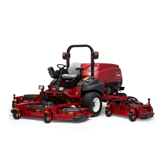
Page 21: Product Overview
Product Overview g031657 Figure 9 1. Wing mower deck 5. Fuel tank 2. Control panel 6. Steering wheel 7. Front mower deck 3. Rollover-Protection System (ROPS) 4. Hood 8. InfoCenter... -
Page 22: Controls
Controls Key Switch Note: The key switch has 3 positions: S Determine the left and right sides of the REHEAT and S (Figure 10). machine from the normal operating position. TART High-Low Range-Speed Switch Press the front of the switch to select HIGH SPEED . -
Page 23: Cab Controls
Throttle Switch Cab Controls Model 31699 Only The throttle switch has 2 positions: LOW IDLE HIGH (Figure 10). IDLE Press the switch forward for 2 or more seconds to set the throttle at H ; press the switch rearward for 2 or more seconds to set the throttle at L or momentarily press the switch in either direction to increase or decrease the engine speed in 100-rpm increments. -
Page 24: Infocenter Control
InfoCenter Control Pull out and down on latch to close and secure wind shield. Start-Up Screen When you start the machine, the start-up screen appears, displaying the corresponding icons that apply (i.e., the parking brake is applied, the PTO is in the O position, cruise control is in the O position). - Page 25 G033146 g033146 Figure 16 1. Tachometer 2. Fuel-level indicator • 12 V battery-voltage indicator—top, left screen G033145 g033145 (Figure Figure 15 • 24 V battery-voltage indicator—top, left 6. Audible alarm 1. Screen 1—top, left screen screen(Figure 2. Button 1 7. Button 4 3.
- Page 26 (Figure 14) appears on the screen, needed. A reverse cycle automatically initiates to immediately contact your Toro distributor for service; help blow debris off the respective hood screen, refer to Diesel Particulate Filter Regeneration (page when either the temperature of the engine coolant 48).
- Page 27 If you have an issue that requires use of the Service screen (i.e., calibrating the traction pedal), contact 1. Press and hold the far, right button on the your Authorized Toro Service Dealer for assistance. InfoCenter. Note: The Main Menu screen appears.
- Page 28 G033170 G033168 g033170 g033168 Figure 22 Figure 20 6. Enter the default PIN, 5900, into the Enter PIN 4. Press button 2 until you reach PIN Settings on screen by using buttons 1 to 4 to select the the Display screen and press button 4 to select digits and press button 5 to complete the PIN PIN Settings (Figure...
- Page 29 Changing the InfoCenter PIN 1. From the start-up screen, press and hold button 5 until the Main Menu appears (Figure 19). 2. Press button 2 until you reach Settings on the Main Menu screen and press button 4 to select Settings (Figure 19).
- Page 30 Changing the InfoCenter Display Brightness/Contrast 1. From the start-up screen, press button 5 to access the brightness/contrast pop-up-menu (Figure 27). G033179 g033179 Figure 28 1. Cruise-control selection G033178 4. From the Cruise Control screen, press button 1 to decrease the cruise-control speed or button 2 g033178 to increase the cruise-control speed (Figure...
- Page 31 InfoCenter Advisories Operator advisories automatically display on the InfoCenter screen when a machine function requires additional action. For example, if you attempt to start the engine while pressing the traction pedal, an advisory displays, indicating that the traction pedal must be in the N position.
- Page 32 PTO Denied Hydraulic oil too cold To engage PTO, let hydraulic oil warm up Cruise Control Denied Too slow to capture cruise Increase ground speed control Deck Lower Denied To lower deck, return traction Can’t lower in transport pedal to N EUTRAL Deck Lower Denied Out of seat...
- Page 33 Engine Advisory 1210 Engine derate due to high Let engine cool temperature Engine Advisory 1211 Engine speed restricted: Hydraulic oil is less than 4°C hydraulic oil too cold (40°F), so derate the engine speed to 1,650 rpm Fuel Level 1302 Fuel level is low Add fuel TP Not Calibrated...
-
Page 34: Specifications
Contact your Authorized Service Dealer or Distributor or go to www.Toro.com for a list of all approved attachments and accessories. To best protect your investment and maintain optimal performance of your Toro equipment, count on Toro genuine parts. -
Page 35: Fuel Safety
Fuel Safety Operation DANGER Note: Determine the left and right sides of the machine from the normal operating position. In certain conditions, fuel is extremely flammable and highly explosive. A fire or explosion from fuel can burn you and others Before Operation and can damage property. -
Page 36: Checking The Engine-Oil Level
Fuel filter plugging may be expected for a time after converting to biodiesel blends. • Do not use fuel additives. • Contact your Authorized Toro Distributor if you Petroleum Diesel wish for more information on biodiesel. Cetane rating: 45 or higher Sulfur content: Ultra-low sulfur (<15 ppm) -
Page 37: Adding Fuel
Check the air pressure in all the tires before operating the machine. Traction performance, including tire-slip control, is dependent on the ratio of the tire size between the front and rear tires. Only use genuine Toro tires. g001055 Figure 32... -
Page 38: Checking The Torque Of The Wheel-Lug Nuts
Checking the Torque of the Wheel-Lug Nuts Service Interval: After the first 10 hours Every 250 hours WARNING g031660 Failure to maintain the proper torque of the Figure 33 wheel nuts could result in failure or loss of a 1. Caster wheel height-of-cut 2. - Page 39 Adjusting the Wing Mower Decks 8. Install the tensioning cap and tighten it with the supplied caster-cap wrench to secure the 1. Start the engine and raise the mower decks so assembly (Figure 34). you can change the height of cut. 9.
-
Page 40: Adjusting The Skids
g031661 Figure 38 1. Tensioning cap 4. Top axle-mounting hole 2. Spacers (6) 5. Caster wheel 3. Shims (2 top and 2 bottom) 5. 5. Install 2 shims onto the shaft as originally installed and slide the appropriate number of spacers onto the shaft to get the desired height of cut. -
Page 41: Adjusting The Mower Deck Anti-Scalp Rollers
Adjusting the Outer Skids Adjusting the Mower Deck Anti-Scalp Rollers Mount the outer skids in the lower position when operating at heights of cut greater than 51 mm (2 inches) and in the higher position when operating at Mount the roller in the lower position when operating heights of cut lower than 51 mm (2 inches). -
Page 42: Checking A Mismatch Between Mower Decks
Checking a Mismatch Matching the Height of Cut Between Mower Decks Between Mower Decks 1. Position the blade side to side on the outside Due to differences in grass conditions and the spindle of both wing mower decks. counterbalance setting of the traction unit, you should 2. - Page 43 Note: Check the measurement between the outside edges of both wing mower decks and the inside edge of the wing mower deck to the outside edge of the front mower deck again. 8. If the inside edge is still too low, add an additional shim to the bottom of front, inside caster arm of the wing mower deck and 1 shim to the front, outside caster arm of the wing mower deck.
-
Page 44: Adjusting The Mirrors
Adjusting the Mirrors Checking the Safety-Interlock Switches Model 31699 Only CAUTION Rear-View Mirror If safety-interlock switches are disconnected While sitting in the seat, adjust the rear-view mirror or damaged, the machine could potentially to attain the best view out of the rear window. Pull operate unexpectedly, causing personal the lever rearward to tilt the mirror to reduce the injury. -
Page 45: Checking The Blade Stopping Time
Do not mow on wet grass. Reduced traction could the time is greater than 7 seconds, adjust the braking cause the machine to slide. valve; contact your Toro Distributor for assistance in • Never raise the mower deck with the blades making this adjustment. -
Page 46: Starting And Stopping The Engine
Use accessories and attachments approved by starts and allow it to return to the R position. The Toro® Company only. 6. Allow the engine to warm up at low speed (without load) for 3 to 5 minutes, then actuate Rollover Protection System... -
Page 47: Raising Or Lowering The Decks
Cutting Grass with the position, set the parking brake, and turn the ignition key to O Machine 8. Remove the key from the switch to prevent accidental starting. Note: Cutting grass at a rate that loads the engine promotes DPF regeneration. Important: Allow the engine to idle for 5 minutes before shutting it off after a full-load operation. -
Page 48: Diesel Particulate Filter Regeneration
Diesel Particulate Filter speed to help reduce the accumulation of soot in the soot filter. Regeneration CAUTION The diesel particulate filter (DPF) is part of the exhaust The exhaust temperature is hot (approximately system. The diesel-oxidation catalyst of the DPF reduces harmful gasses and the soot filter removes 600°C (1112°F) during DPF parked soot from the engine exhaust. - Page 49 DPF Ash Accumulation • When enough ash accumulates, the engine computer sends information to the InfoCenter in • The lighter ash is discharged through the exhaust the form of a system advisory or an engine fault to system; the heavier ash collects in the soot filter. indicate the accumulation of ash in the DPF.
- Page 50 Regeneration Unavailable Messages Unavailable Message Table Message Condition Recommended Action The engine is not running. Start the engine. g214114 Figure 54 Run the engine until the coolant The engine coolant temperature temperature is hotter than 60°C is cooler than 60°C (140°F). (140°F).
- Page 51 Unavailable Message Table (cont'd.) Message Condition Recommended Action The parking brake is not engaged. Engage the parking brake. g214110 Figure 58 The traction pedal is in the Move the traction pedal to the N EUTRAL position. position. FORWARD REVERSE g214113 Figure 59 The engine computer has sent a Troubleshoot the diagnostic fault code...
- Page 52 Types of Diesel Particulate Filter Regeneration Types of diesel particulate filter regeneration that are performed while the machine is operating: Type of Regeneration Conditions for DPF regeneration DPF description of operation Passive Occurs during normal operation of the machine at The InfoCenter does not display an icon indicating high-engine speed or high-engine load passive regeneration.
- Page 53 Passive DPF Regeneration operate the machine (Figure 63), a critical amount of soot may accumulate in the DPF. • Passive regeneration occurs as part of normal engine operation. • While operating the machine, run the engine at full-engine speed when possible to promote DPF regeneration.
- Page 54 g214647 Figure 65 g214884 • Figure 66 If you are authorized by your company, you need the PIN code to perform the recovery-regeneration process. 2. On the menu, press button 1 or button SERVICE 2 to navigate to the option, and REGENERATION Preparing to Perform a Parked or Recovery press button 4 to select the...
- Page 55 Note: If you press button 5 while the regeneration is processing, you will exit the regeneration process. At the screen press EXIT button 5 to return to the menu (Figure SERVICE 70). g214486 Figure 68 g214485 4. The InfoCenter displays a series of screens Figure 70 (Figure 69) as the regeneration processes:...
-
Page 56: Understanding The Operating Characteristics Of The Machine
The 2 large 12 V batteries at With Toro Smart Power™, the operator does not have the rear, right corner of the machine are connected in to listen to the engine speed in heavy load conditions. -
Page 57: Operating Tips
Operating Tips • Ensure that the air-conditioning screen is clean. • Ensure that the air-conditioning-condenser fins are clean. Selecting the Proper Height-of-Cut • Operate the air-conditioner blower at the Setting mid-speed setting. Remove approximately 25 mm (1 inch) or no more •... -
Page 58: After Operation
Pushing or Towing the After Operation Machine After Operation Safety Important: Do not push or tow the machine faster than 3 to 4.8 km/h (2 to 3 mph), because internal-transmission damage may occur. General Safety 1. Raise the hood and locate the bypass valves •... -
Page 59: Identifying The Tie-Down Points
Identifying the Tie-Down Points Front of the machine—under the front of the operator's platform (Figure g008997 Figure 77 1. Front tie downs Rear of the machine—on the bumper (Figure g031557 Figure 76 g009005 Figure 78 5. Close the bypass valves before starting the 1. -
Page 60: Maintenance
Maintenance Note: Determine the left and right sides of the machine from the normal operating position. Important: Refer to your engine operator's manual for additional maintenance procedures. Recommended Maintenance Schedule(s) Maintenance Service Maintenance Procedure Interval • Check the wheel-lug nuts. •... -
Page 61: Daily Maintenance Checklist
Maintenance Service Maintenance Procedure Interval • Check and replace (if necessary) fuel hoses and engine-coolant hoses. Every 2,000 hours • Lap or adjust the engine intake and exhaust valves (if necessary). • Inspect and clean (if necessary) the engine-emission-control components and Every 3,000 hours turbocharger. - Page 62 For the week of: Maintenance Check Item Monday Tuesday Wednesday Thursday Friday Saturday Sunday Touch up any damaged paint. Check the glow plug, injector nozzles and engine air filters if starting is hard, there is excess smoke, or rough running is noted. Immediately after every washing, regardless of the interval listed.
-
Page 63: Service-Interval Chart
Notation for Areas of Concern Inspection performed by: Item Date Information Service-Interval Chart decal132-1407 Figure 79... -
Page 64: Pre-Maintenance Procedures
If your machine requires major repairs or if you desire assistance, contact an Authorized Toro Distributor. • Use only genuine Toro replacement parts and accessories. Replacement parts and accessories made by other manufacturers could be dangerous, and such use could void the product warranty. -
Page 65: Raising The Machine
Raising the Machine Removing and Installing the Inner-Wing-Deck Covers Use the following as points to jack up the machine: Front of the machine—on the frame, on the inside of Removing the Inner-Wing-Deck each drive tire (Figure Covers 1. Lower the wing deck onto a level surface. 2. -
Page 66: Lubrication
Lubrication Greasing the Bearings and Bushings Service Interval: Every 50 hours—Lubricate all grease fittings. The machine has grease fittings that you must lubricate regularly with No. 2 lithium grease. Also, lubricate the machine immediately after every washing. g013894 Figure 85 Traction Unit 1. - Page 67 g031674 Figure 86 Front Mower Deck • 2 caster-fork-shaft bushings (Figure • 5 spindle-shaft bearings (located on the spindle housing) as shown in Figure 89 • 3 idler-arm-pivot bushings (located on the idler-pivot shaft) as shown in Figure 89 • 4 winglet-deck bushings (located on the winglet-pivot pins) as shown in Figure 89...
- Page 68 Front Lift Assemblies Wing Lift Assemblies (Per Wing) • • 2 lift-arm bushings (Figure 3 main lift-arm bushings (Figure • • 2 lift-arm-ball joints (Figure 1 lift-cylinder bushing (Figure • 2 front deck lift-cylinder pivots (Figure g009248 Figure 92 g009247 Figure 90 Wing Mower Decks (Each Wing) •...
-
Page 69: Engine Maintenance
Engine Maintenance Important: Do not directly contact the engine-control unit (ECU) or electrical connectors with water, as this may cause damage; refer to Figure 93 for the ECU and electrical connections location. g021 157 g021157 Figure 94 Servicing the Air-Cleaner Cover g033303 Service Interval: Every 50 hours—Remove the Figure 93... - Page 70 Servicing the Air-Cleaner Filter elements Service Interval: Every 400 hours Every 400 hours The air-intake system on this machine is continuously monitored by an air-restriction sensor that will display an advisory when the air filter needs to be replaced. Do not replace the elements until this occurs. Important: Replace the secondary filter element only every 3 primary filter services.
-
Page 71: Servicing The Engine Oil
Preferred oil: SAE 15W-40 (above 0°F) • Alternate oil: SAE 10W-30 or 5W-30 (all temperatures) Toro Premium Engine Oil is available from your Authorized Toro Distributor in either 15W-40 or 10W-30 viscosity grades. See the parts catalog for part numbers. - Page 72 Crankcase Oil Capacity 10.4 L (11 US qt) with the filter Changing the Engine Oil and Engine-Oil Filter Service Interval: After the first 50 hours—Change the engine oil and engine-oil filter. Every 500 hours—Change the engine oil and g031551 engine-oil filter. Note: Change the engine oil and filter more frequently when the operating conditions are extremely dusty...
-
Page 73: Adjusting The Engine-Valve Clearance
Adjusting the Engine-Valve 4. Change the engine-oil filter (Figure 101). Note: Clearance Ensure that the oil-filter gasket touches the engine, and then an extra 3/4 turn is completed. Service Interval: Every 1,000 hours Refer to your engine operator’s manual for the adjustment procedure. -
Page 74: Inspecting And Cleaning Engine-Emission-Control Components And Turbocharger
Inspecting and Cleaning 2. Refer to your Authorized Toro Distributor for diesel-oxidation catalyst and the soot filter Engine-Emission-Control replacement parts or service. Components and 3. Contact your Authorized Toro Distributor to have them reset the engine ECU after you install a Turbocharger clean DPF. -
Page 75: Fuel System Maintenance
Fuel System 3. Tighten the valve after draining. Maintenance Replacing the Water-Separator Element Servicing the Fuel System 1. Place a clean container under the water separator. Draining the Fuel Tank 2. Drain some fuel by loosening the vent plug and opening the drain valve (Figure 105). -
Page 76: Replacing The Fuel Filter Element
(Figure 111) or the cab-fuse block (Figure 113). A maximum of 10 A is available from either location. Contact your local Toro distributor for assistance. Note: Shut off the engine and remove the key before removing the fuses. - Page 77 g033314 Figure 110 1. Fuse block g031737 Figure 107 g033290 Figure 111 1. Fuse block 2. Power leads The cab fuses (Figure 112) are located in the fuse box on the cab headliner (Figure 113). g031738 Figure 108 1. Power-center console 2.
-
Page 78: Checking The Condition Of The Batteries
To clean the battery, wash the entire case with a solution of baking soda and water. Rinse with clear water. Coat the battery posts and cable connectors with Grafo 112X (skin-over) grease (Toro Part No. 505-47) or petroleum jelly to prevent corrosion. g031800 Figure 114 1. -
Page 79: Jump-Starting The Machine
1. Park the machine on a level surface, stop the engine, and remove the ignition key. 2. Sit in the operator seat and have the other person make the connections. Note: Ensure that the jumper battery is a 12-volt battery. Important: If you are using another machine for power, ensure that the 2 machines are... -
Page 80: Drive System Maintenance
Drive System Maintenance Calibrating the Traction Pedal Service Interval: Every 1,000 hours—Calibrate the traction pedal. Contact your local Toro distributor or refer to the Toro Service Manual for assistance. Adjusting the g034932 Figure 118 Traction-Pedal Angle 1. Outside distance 2. Tie-rod clamps You can adjust the operating angle of the traction 2. -
Page 81: Cooling System Maintenance
Cooling System DANGER The rotating fans and drive belts can cause Maintenance personal injury. • Do not operate the machine without the Cooling System Safety covers in place. • Keep fingers, hands, and clothing clear of CAUTION the rotating fan and drive belt. •... -
Page 82: Cleaning The Cooling Systems
Cleaning the Cooling Systems Service Interval: Before each use or daily Perform the pre-maintenance procedure; refer to Pre-Maintenance Safety (page 64). Important: Do not use water to clean the radiator core or hydraulic-fluid-cooler core. Cleaning the radiator core or hydraulic-fluid-cooler core with water can promote premature corrosion and damage to components. -
Page 83: Changing The Engine-Cooling-System Fluid
g033289 Figure 123 1. Hydraulic-fluid cooler 3. Prop rod 2. Hydraulic-cooling fans g031321 Figure 124 1. Drain valve 3. Radiator 2. Radiator-drain hose Changing the Engine-Cooling- 4. Close the valve on the radiator-drain hose (Figure 124). System Fluid 5. Fill the radiator with coolant until the coolant level even with the lip of the filler port (Figure Service Interval: Every 1,000 hours—Flush the... -
Page 84: Belt Maintenance
10. Start and run the engine until it reaches spring-loaded tensioner that is pre-set at the factory. operating temperature. Refer to the Toro Service Manual for the servicing procedure. 11. Check the engine-coolant level; refer to Checking the Engine-Cooling System (page 81). - Page 85 8. Route the new belt around the spindle pulleys and idler-pulley assembly (Figure 129). 114-0922 decal114-0922nc Figure 129 9. Adjust the stop screw on the idler pulley and tighten the jam nuts. 10. Install the belt covers. Replacing the Wing Mower-Deck Belts g009014 Figure 127...
-
Page 86: Hydraulic System Maintenance
(Available in 5-gallon pails or 55-gallon drums. See the Parts Catalog or Toro distributor for part numbers.) If the Toro fluid is not available, you may use other fluids provided that they meet all the following material properties and industry specifications. Consult with your lubricant distributor to identify a satisfactory product. -
Page 87: Changing The Hydraulic Fluid And Filters
Toro distributor because the system must be flushed. Contaminated fluid looks milky or black when compared to clean oil. Use Toro replacement filters (Part No. 86-6110 for the left side of the machine and Part No. 75-1310 for the right side of the machine). -
Page 88: Checking The Hydraulic Lines And Hoses
5. Install the drain plug when the hydraulic fluid hydraulic circuits. Contact your local Toro distributor stops draining. or refer to the Toro Service Manual for assistance. 6. Clean the area around the filter-mounting areas. 7. Place a drain pan under the filter and remove... -
Page 89: Mower Maintenance
Mower Maintenance Pivoting (Tilting) the Front Mower Deck Upright Note: Although not needed for normal maintenance procedures, you can pivot (tilt) the front mower deck upright. 1. Raise the front mower deck slightly off the floor. 2. Perform the pre-maintenance procedure; refer Pre-Maintenance Safety (page 64). -
Page 90: Pivoting (Tilting) The Front Mower Deck Down
Pivoting (Tilting) the Front 3. Measure from the floor to the back tip of the winglet blade and record this dimension. Mower Deck Down 4. Subtract the front dimension from the rear dimension to calculate the pitch of each blade. 1. -
Page 91: Servicing The Caster-Arm Bushings
Adjusting the Wing Mower-Deck Servicing the Caster Pitch Wheels and Bearings 1. Remove the tensioning cap from the Service Interval: Every 500 hours—Inspect caster-spindle shaft and slide the spindle out of the mower deck caster-wheel the caster arm (Figure 141). assemblies. -
Page 92: Blade Maintenance
Replace the blade if it hits a solid object, if it is out blade may result in discontinued safety of balance, or if it is bent. Always use genuine Toro certification of the product. replacement blades to be sure of safety and optimum •... -
Page 93: Inspecting And Sharpening A Blade
Inspecting and Sharpening a Blade Service Interval: After the first 10 hours Every 50 hours g000276 Before each use or daily Figure 146 You must consider 2 areas of the blade when checking 1. Sharpen at the original angle. and servicing it: the sail and the cutting edge. Both cutting edges and the sail, which is the turned-up portion opposite of the cutting edge, contribute to a Note:... -
Page 94: Cab Maintenance
Cab Maintenance Cleaning the Cab For Machines with a Cab Important: Use care around the cab seals and lights (Figure 147). If you are using a pressure washer, keep the washer wand at least 0.6 m (2 ft) away from the machine. Do not use the pressure washer directly on the cab seals and lights or under the rear overhang. -
Page 95: Cleaning The Air-Conditioning-Condenser Coil
C. Coat the cable terminals and battery posts 4. Open the 4 latches on the air-conditioning with Grafo 112X skin-over grease (Toro Part assembly and remove the screen (Figure 151). No. 505-47) or petroleum jelly to prevent corrosion. - Page 96 9. Seal the air-cleaner inlet and the exhaust outlet with weatherproof tape. 10. Check the anti-freeze protection and add a 50/50 solution of water and ethylene glycol anti-freeze as needed for the expected minimum temperature in your area.
- Page 97 Notes:...
- Page 98 Notes:...
- Page 99 The Way Toro Uses Information Toro may use your personal information to process warranty claims, to contact you in the event of a product recall and for any other purpose which we tell you about. Toro may share your information with Toro's affiliates, dealers or other business partners in connection with any of these activities. We will not sell your personal information to any other company.
- Page 100 Countries Other than the United States or Canada Customers who have purchased Toro products exported from the United States or Canada should contact their Toro Distributor (Dealer) to obtain guarantee policies for your country, province, or state. If for any reason you are dissatisfied with your Distributor's service or have difficulty obtaining guarantee information, contact the Toro importer.