Toro Groundsmaster 5900 Operator's Manual
Hide thumbs
Also See for Groundsmaster 5900:
- Operator's manual (100 pages) ,
- Software manual (16 pages) ,
- Installation instructions manual (12 pages)
Chapters
Table of Contents

Related Manuals for Toro Groundsmaster 5900


Summary of Contents for Toro Groundsmaster 5900
- Page 1 Form No. 3440-765 Rev A Groundsmaster ® 5900 or 5910 Rotary Mower Model No. 31698—Serial No. 407050000 and Up Model No. 31699—Serial No. 407050000 and Up *3440-765* Register at www.Toro.com. Original Instructions (EN)
- Page 2 Section 4442 or 4443 to use or operate the engine on additional information, contact an Authorized Service any forest-covered, brush-covered, or grass-covered Dealer or Toro Customer Service and have the model land unless the engine is equipped with a spark and serial numbers of your product ready.
-
Page 3: Table Of Contents
Contents General Safety ..........57 Understanding the Audible Alarm ..... 57 Pushing or Towing the Machine ......58 Safety ............... 4 Identifying the Tie-Down Points ......59 General Safety ........... 4 Hauling the Machine ......... 59 Safety and Instructional Decals ......5 Maintenance ............ -
Page 4: Safety
Safety Servicing the 24 V Alternator Belt and AC Compressor Belt ........... 84 Replacing the Blade-Drive Belts ....... 84 This machine has been designed in accordance with Hydraulic System Maintenance ......86 ANSI B71.4-2017 and with EN ISO 5395 when you Hydraulic System Safety........ -
Page 5: Safety And Instructional Decals
Safety and Instructional Decals Safety decals and instructions are easily visible to the operator and are located near any area of potential danger. Replace any decal that is damaged or missing. decal93-6674 93-6674 decal106-6754 1. Crushing hazard, hand—read the instructions before 106-6754 servicing or performing maintenance. - Page 6 decal115-8155 115-8155 1. Warning—read the Operator's Manual, do not prime or use 114-0922 starting fluid. decal114-0922 114-0922 1. Belt routing decal117-3276 117-3276 1. Engine coolant under 3. Warning—do not touch the pressure hot surface. 2. Explosion hazard—read 4. Warning—read the decal114-0974 the Operator's Manual.
- Page 7 decal120-6604 120-6604 1. Thrown object hazard—keep bystanders away from the machine. 2. Cutting/dismemberment hazard of hand, mower blade—stay away from moving parts; keep all guards and shields in place. 3. Cutting/dismemberment hazard of foot, mower blade—stay away from moving parts; keep all guards and shields in decal130-0594 130-0594 place.
- Page 8 decal131-6025 131-6025 1. Height of cut decal132-1313 132-1313 1. Attention—move the 4. Positive terminal key to the engine stop position before servicing the battery; do not service the battery with the engine running. 2. Battery—disconnect 5. Negative terminal 3. Battery—connect 6.
- Page 9 decal132-1406 132-1406 decal133-0980 1. Releasing the parking 2. Engaging the parking 133-0980 brake when the engine brake—pull up the black Model with Cab Only is off—1) Open the tow knob; the manual valve valves on the traction resets when you start the 1.
- Page 10 decalbatterysymbols Battery Symbols Some or all of these symbols are on your battery. 1. Explosion hazard 6. Keep bystanders away from the battery. 2. No fire, open flame, or 7. Wear eye protection; smoking explosive gases can cause blindness and other decal136-1003 136-1003 injuries.
- Page 11 decal117-2754 117-2754 1. Warning—read the Operator's Manual. 2. Warning—do not operate this machine unless you are trained. 3. Warning—wear the seatbelt when seated in the operator's position. 4. Warning—wear hearing protection. 5. Thrown object hazard—keep bystanders away. 6. Cutting hazard of hand or foot—stay away from moving parts; keep all guards and shields in place. 7.
- Page 12 decal121-8378 121-8378 Model with Cab Only 1. Fan—off 3. Cold air 5. External air 7. Air conditioner—on 4. Hot air 6. Internal air 2. Fan—on full 8. Air conditioner—off...
- Page 13 decal131-2348 131-2348 1. Headlights—off 4. Parking brake—off 7. Engine—stop 2. Headlights—on 5. Pivot the attachment left. 8. Engine—run, electric preheat 3. Parking brake—on 6. Pivot the attachment right. 9. Engine—start decal131-6027 131-6027 1. Height-of-cut settings 3. Lower caster position—heights of cut 76 to 153 cm (3 to 6 inches) 2.
- Page 14 decal132-1321 132-1321 1. Read the Operator’s Manual. 4. To engage the PTO, pull up the knob. 2. To start the engine: 1) Put the traction pedal in neutral; 2) 5. To disengage the PTO, push down the knob. Engage the parking brake; 3) Turn the key to the run position; 4) Turn the key to the engine start position.
- Page 15 decal136-1004 136-1004 1. Turn signals 7. Cutting unit—off 2. Beacon 8. Lower the left cutting unit. 3. Work light 9. Lower the center cutting unit. 4. Engine speed 10. Lower the right cutting unit. 5. Transmission 11. Horn 6. Cutting unit—on decal139-0977 139-0977 1.
-
Page 16: Setup
Setup Loose Parts Use the chart below to verify that all parts have been shipped. Procedure Description Qty. Remove the wing-deck-shipping straps – No parts required and braces. Right deck cover Left deck cover Lower the front-deck winglets. V-belt Check the tire and caster wheel –... -
Page 17: Lowering The Front-Deck Winglets
Remove the straps and braces securing the Install the front and rear stop bolts through the wing decks for shipping. upper-mounting holes and eccentrics (Figure Note: Ensure that the stop bolt engages the tab on the hinge pin. Lowering the Front-Deck Winglets Parts needed for this procedure: Right deck cover... -
Page 18: Checking The Tire And Caster Wheel Pressure
Using a ratchet wrench or a similar tool, tire size between the front and rear tires. Use only move the idler pulley away from the pulleys genuine Toro tires. (Figure Route the belt around the winglet-spindle pulley and the upper-spindle pulley on the front deck. -
Page 19: Checking The Fluid Levels
Adjust the forward eccentric until it just makes contact with the inner slot surface of the winglet-pivot brackets. Tighten the bolt and nut for this eccentric to 149 N·m (110 ft-lb). Repeat the procedure on the opposite winglet. Checking the Fluid Levels No Parts Required Procedure g008868... -
Page 20: Installing The Decal
Installing the Decal (CE Machines Only) Parts needed for this procedure: Production-year decal Procedure On machines requiring CE compliance, install the production-year decal included in the loose parts and the CE Kit, sold separately (Figure g282517 Figure 9 1. Production-year decal... -
Page 21: Product Overview
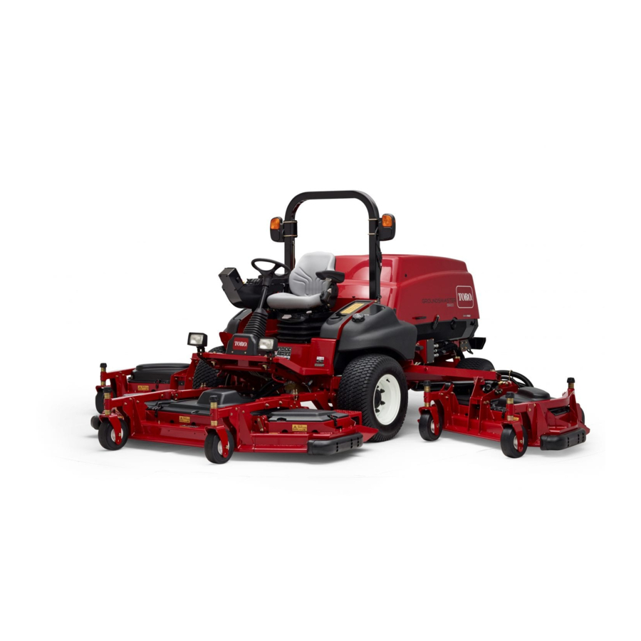
Product Overview g031657 Figure 10 1. Wing cutting unit 5. Fuel tank 2. Control panel 6. Steering wheel 3. Roll bar 7. Front cutting unit 4. Hood 8. InfoCenter... -
Page 22: Controls
Controls Turn-Signal Switch Press the left side of the turn-signal switch to activate Note: Determine the left and right sides of the the left-turn signal and the right side of the switch to machine from the normal operating position. activate the right-turn signal (Figure 11). - Page 23 Throttle Switch Seat-Back-Adjustment Lever The throttle switch has 2 positions: Move the lever to adjust the seat-back angle (Figure LOW IDLE HIGH (Figure 11). 12). IDLE Press the switch forward for 2 or more seconds to set Weight Gauge the throttle at H ;...
-
Page 24: Cab Controls
Cab Controls position. Pull out and down on the latch to close and secure the windshield. For Machines with a Cab g196911 Figure 14 1. Windshield latch g032672 Figure 13 Rear Window Latch 1. Air-conditioning switch 4. Temperature control Lift up the latches to open the rear window. Press in 2. -
Page 25: Specifications
Specifications Note: Specifications and design are subject to change without notice. g200003 Figure 15 Description Figure 15 Dimension or Weight reference Height with cab 240 cm (94.5 inches) Height with roll bar 216 cm (85 inches) Overall length 442 cm (174 inches) Length for storage or transport 434 cm (171 inches) -
Page 26: Attachments/Accessories
To ensure optimum performance and continued safety certification of the machine, use only genuine Toro replacement parts and accessories. Replacement parts and accessories made by other manufacturers could be dangerous, and such use could void the... -
Page 27: Before Operation
Operation • Do not store the machine or fuel container where there is an open flame, spark, or pilot light, such as on a water heater or other appliance. Note: Determine the left and right sides of the • If you spill fuel, do not attempt to start the engine; machine from the normal operating position. - Page 28 Monitor seals, hoses, gaskets in contact with fuel as they may degrade over time. • Fuel filter plugging may occur for a time after you convert to biodiesel blends. • For more information on biodiesel, contact your authorized Toro distributor.
-
Page 29: Checking The Tire Pressure
Check the air pressure in all the tires before operating the machine. Traction performance, including tire-slip control, is dependent on the ratio of the tire size between the front and rear tires. Use only genuine Toro tires. g001055 Figure 17... -
Page 30: Adjusting The Height Of Cut
caster-spindle shaft and slide the caster shaft WARNING out of the caster arm (Figure 19). Failure to maintain the proper torque of the wheel nuts could result in failure or loss of a wheel, and may result in personal injury. Torque the front and rear-wheel nuts to 135 to 150 N·m (100 to 110 ft-lb) according to the maintenance schedule. - Page 31 Adjusting the Wing Cutting Units Start the engine and raise the cutting units so you can change the height of cut. Shut off the engine and remove the key after you raise the cutting unit. Position the caster-wheel axles in the same holes in all of the caster forks;...
-
Page 32: Adjusting The Skids
Adjusting the Skids Adjusting the Inner Skids Mount the inner skids in the lower position when operating at heights of cut greater than 51 mm (2 inches) and in the higher position when operating at heights of cut lower than 51 mm (2 inches). Adjust the inner skids (Figure 24). -
Page 33: Adjusting The Cutting Unit Anti-Scalp Rollers
Adjusting the Cutting Unit Anti-Scalp Rollers Mount the roller in the lower position when operating at heights of cut greater than 51 mm (2 inches) and in a higher position when operating at heights of cut lower than 51 mm (2 inches). g202202 Adjusting the Roller Remove the roller shaft, screw, and nut securing... -
Page 34: Correcting A Mismatch Between The Cutting Units
Correcting a Mismatch Matching the Height of Cut Between Cutting Units Between the Cutting Units Position the blade side to side on the outside Due to differences in grass conditions and the spindle of both wing cutting units. counterbalance setting of the traction unit, you should Measure from the floor to the tip of the cut the grass and check the appearance before you cutting edge on both units and compare the... -
Page 35: Adjusting The Mirrors
Note: Check the measurement between the outside edges of both wing cutting units and the inside edge of the wing cutting unit to the outside edge of the front cutting unit again. If the inside edge is still too low, add an additional shim to the bottom of front, inside caster arm of the wing cutting unit and 1 shim to the front, outside caster arm of the wing cutting unit. -
Page 36: Checking The Safety-Interlock Switches
If the time the engine, and engage the parking brake. is greater than 7 seconds, adjust the braking valve; contact your authorized Toro distributor for assistance With the engine running, move the traction pedal in making this adjustment. -
Page 37: During Operation
Make all Roll Bar necessary repairs before resuming operation. • A cab installed by Toro is a roll bar. • Slow down and use caution when making turns • Always wear your seat belt. -
Page 38: Starting The Engine
Starting the Engine surveying the site. Always use common sense and good judgment when performing this survey. Ensure that the parking brake is engaged. • Review the slope instructions listed below for Remove your foot from the traction pedal and operating the machine on slopes and to determine ensure that it is in the N position. -
Page 39: Diesel Particulate Filter Regeneration
Diesel Particulate Filter machine into or out of a building), you will not be able raise all the cutting units at once. Instead, Regeneration you can only raise 1 cutting unit at a time. Push the deck-lift switches rearward to raise The diesel particulate filter (DPF) is part of the exhaust the decks. - Page 40 DPF Soot Accumulation • Over time, the diesel particulate filter accumulates soot in the soot filter. The computer for the engine monitors the soot level in the DPF. • When enough soot accumulates, the computer informs you that it is time to regenerate the DPF. •...
- Page 41 InfoCenter Advisory and Engine Warning Messages—Ash Accumulation Indication Engine Speed Fault Code Engine Power Rating Recommended Action Level Reduction Service the DPF; Level 1: The computer refer to Servicing the Engine None de-rates the engine Diesel-Oxidation Catalyst Warning power to 85%. (DOC) and the Soot Filter (page 71) g243501...
- Page 42 Types of Diesel Particulate Filter Regeneration Types of diesel particulate filter regeneration that are performed while the machine is operating: Type of Regeneration Conditions that cause DPF regeneration DPF description of operation Passive Occurs during normal operation of the machine at •...
-
Page 43: Parked Or Recovery Regeneration
Types of diesel particulate filter regeneration that require you to park the machine: (cont'd.) Type of Regeneration Conditions that cause DPF regeneration DPF description of operation Recovery Occurs because the operator ignored requests for • When the reset-standby/parked or recovery a parked regeneration and continued operating the machine, adding more soot to the DPF regeneration icon... - Page 44 Press the button 4 to select the Technician entry (Figure The state and soot load information displays. • Use the DPF operation table to understand the current state of DPF operation (Figure 39). g241812 Figure 37 Press button 4 to return to the DPF regeneration screen or press button 5 to exit the service menu and return to the home screen.
- Page 45 Reset Regeneration Note: The soot load value varies as the machine is operated and DPF regeneration occurs. CAUTION The exhaust temperature is hot (approximately 600°C (1,112°F) during DPF regeneration. Hot exhaust gas can harm you or other people. • Never operate the engine in an enclosed area.
- Page 46 Periodic Reset Regeneration Press the button 4 to select the Inhibit Regen entry (Figure 43). If the engine has not completed a successful Reset, Press the button 4 to change the inhibit Parked, or Recovery regeneration in the previous 100 regeneration setting from On to Off (Figure hours of engine operation, the engine computer will...
-
Page 47: Parked Regeneration Or A Recovery Regeneration
g241833 Figure 46 g243501 Note: When the reset regeneration completes, the Figure 48 high exhaust-temperature disappears from the • Parked regeneration required A #1212 DVISORY InfoCenter screen. (Figure Note: Advisory #1212 displays every 15 minutes. Parked or Recovery Regeneration • When the engine computer requests either a parked regeneration or a recovery regeneration, the regeneration request icon... -
Page 48: Figure 53
Recovery Regeneration Messages When a recovery regeneration is requested by the engine computer, the following messages display in the InfoCenter: Recovery regeneration required—power takeoff disabled A #1214 (Figure DVISORY g241848 g241999 Figure 51 Important: Perform a recovery regeneration to restore the PTO function; refer to Preparing to Perform a Parked or Recovery Regeneration (page Parked or Recovery Regeneration (page... -
Page 49: Recovery Regeneration
Preparing to Perform a Parked or Recovery Regeneration Ensure that the machine has fuel in the tank for the type of regeneration you are performing: • Parked Regeneration: Ensure that you have 1/4 tank of fuel before performing the parked regeneration. •... - Page 50 g241892 g241894 g241893 g241895 Figure 55 Figure 56 At the V screen, verify that you At the DPF checklist screen, verify that the ERIFY FUEL LEVEL have 1/4 tank of fuel if you are performing the parking brake is engaged, that the engine speed parked regeneration or 1/2 tank of fuel if you are is set to low idle, press the button 4 to continue performing the recovery regeneration, and press...
- Page 51 g241898 g241900 g241899 g241901 Figure 57 Figure 58 At the I DPF R screen, press the The InfoCenter displays the I NITIATE EGEN NITIATING button 4 to continue (Figure 58). message (Figure 59). EGEN Note: If needed, press button 4 to cancel the regeneration process.
- Page 52 g241912 g241914 g241913 g241915 Figure 59 Figure 60 The InfoCenter displays the time to complete The engine computer checks the engine state message (Figure 60). and fault information. The InfoCenter may display the following messages found in the Note: If needed, press button 4 to cancel the table that follows: regeneration process.
- Page 53 The InfoCenter displays the home screen and Check Message and Corrective Action Table the regeneration acknowledge icon (Figure (cont'd.) appears in the lower right corner of the screen as the regeneration processes. Check Message: Diagnostic trouble code active 1220—press any key. Corrective Action: Troubleshoot the engine fault and retry DPF regeneration.
- Page 54 Press the button 4 to cancel a Parked Regen or cancel a Recovery Regen (Figure 65). g242002 g241969 Figure 63 Canceling a Parked or Recovery Regeneration Use the Parked Regen Cancel or Recovery Regen g242003 Cancel setting to cancel a running parked or recovery Figure 65 regeneration process.
-
Page 55: Understanding The Operating Characteristics Of The Machine
The 2 large 12 V batteries at With Toro Smart Power™, you do not have to the rear, right corner of the machine are connected in listen to the engine speed in heavy load conditions. -
Page 56: Automatic-Reversing Fan Cycle
Service Manual for your traction unit for instructions to adjust the counterbalance pressure. Operating Tips Resolving After-Cut Appearance Refer to the After-cut Appearance Troubleshooting Operating the Machine Guide available at www.Toro.com. • Start the engine and run it at the position HALF IDLE Using Proper Mowing Techniques until it warms up. -
Page 57: After Operation
After Operation appearance may deteriorate and the observed power to cut the turf increases. The mulching baffles also perform well for shredding leaves in the fall. General Safety • Shut off the engine, remove the key, and wait Selecting the Proper Height-of-Cut for all movement to stop before you leave the Setting operator’s position. -
Page 58: Pushing Or Towing The Machine
Pushing or Towing the Machine Important: Do not push or tow the machine faster than 3 to 4.8 km/h (2 to 3 mph). If you push or tow at a faster speed, internal transmission damage may occur. The bypass valves must be open whenever you push or tow the machine. -
Page 59: Identifying The Tie-Down Points
Identifying the Tie-Down Points Front of the machine—under the front of the operator's platform (Figure g008997 Figure 72 1. Front tie downs Rear of the machine—on the bumper (Figure g009005 Figure 73 1. Rear tie downs Hauling the Machine • Remove the key and shut off the fuel (if equipped) before storing or hauling the machine. -
Page 60: Maintenance
Remove the key from the • To ensure safe, optimal performance of the switch before you perform any maintenance. machine, use only genuine Toro replacement • Allow machine components to cool before parts. Replacement parts made by other performing maintenance. - Page 61 Maintenance Service Maintenance Procedure Interval • Inspect the cooling-system hoses. Every 100 hours • Check the wheel-lug nuts. • Check and clean the air-cleaner filter elements. Replace if damaged. • Check the whole air-intake system for leaks, damage, or loose hose clamps. •...
-
Page 62: Daily Maintenance Checklist
Daily Maintenance Checklist Duplicate this page for routine use. For the week of: Maintenance Check Item Monday Tuesday Wednesday Thursday Friday Saturday Sunday Check the safety-interlock operation. Check the brake operation. Check the engine-oil level. Check the cooling-system-fluid level. Drain the water/fuel separator. -
Page 63: Pre-Maintenance Procedures
Pre-Maintenance Raising the Machine Procedures Use the following as points to jack up the machine: Front of the machine—on the frame, on the inside of each drive tire (Figure Using the Battery-Disconnect Switch Open the hood to access the battery-disconnect switch. -
Page 64: Removing And Installing The Inner-Wing-Deck Covers
Removing and Installing the Inner-Wing-Deck Covers Removing the Inner-Wing-Deck Covers Lower the wing deck onto a level surface. Disengage the cover latch. Remove the bolt securing the belt cover (if equipped). Lift the rear and inside cover edges off the g013894 mounting posts (Figure... -
Page 65: Lubrication
Lubrication Traction Unit • 2 impact arms (Figure Greasing the Bearings and • 2 front deck-lift-cylinder pivots (Figure • 2 side deck-lift-cylinder pivots (Figure Bushings • 4 steering-cylinder-ball joints (Figure Service Interval: Every 50 hours—Lubricate all • 2 tie-rod-ball joints (Figure grease fittings. - Page 66 Front Cutting Unit • 3 spindle-shaft bearings (located on the spindle housing) as shown in Figure 85 • 2 caster-fork-shaft bushings (Figure • 2 idler-arm-pivot bushings (located on the • 5 spindle-shaft bearings (located on the spindle idler-pivot shaft) as shown in Figure 85 housing) as shown in Figure 83...
-
Page 67: Engine Maintenance
Engine Maintenance Important: Do not directly contact the engine-control unit (ECU) or electrical connectors with water, as this may cause damage; refer to Figure 87 for the ECU and electrical connections location. g021157 Figure 88 Servicing the Air-Cleaner Cover g033303 Service Interval: Every 50 hours—Remove the Figure 87 air-cleaner cover and clean out the... - Page 68 Servicing the Air-Cleaner Filter Note: Do not clean the used element due to the possibility of damage to the filter media. Elements Note: Replace the secondary filter every 3 Service Interval: Every 250 hours—Check and primary filter services (Figure 92). clean the air-cleaner filter elements.
-
Page 69: Servicing The Engine Oil
Note: When using different oil, drain all old oil from the crankcase before adding new oil. Toro Premium Engine Oil is available from your authorized Toro distributor in either 15W-40 or 10W-30 Crankcase Oil Capacity viscosity grades. See the Parts Catalog for part numbers. - Page 70 g031260 g031551 g031336 Figure 94 Change the engine-oil filter (Figure 95). Note: Ensure that the oil-filter gasket touches g031261 Figure 95 the engine, and then an extra 3/4 turn is completed.
-
Page 71: Adjusting The Engine-Valve Clearance
Adjusting the Engine-Valve Inspecting and Cleaning Clearance Engine-Emission-Control Components and Service Interval: Every 1,000 hours Turbocharger Refer to your engine owner’s manual for the adjustment procedure. Service Interval: Every 3,000 hours Cleaning the Engine EGR For information on inspecting and cleaning the engine-emission-control components, refer to your Cooler engine operator’s manual. -
Page 72: Fuel System Maintenance
DPF. Every 400 hours—Replace the fuel/water Refer to your authorized Toro distributor for separator element. diesel-oxidation catalyst and the soot filter replacement parts or service. Draining the Water Separator... -
Page 73: Replacing The Fuel Filter Element
Replacing the Fuel Filter Element Service Interval: Every 500 hours—Replace the fuel-filter element. Clean the area around the fuel-filter head (Figure 99). g031733 Figure 98 1. Vent plug 3. Drain valve 2. Water separator/filter Tighten the valve after draining. g031734 Figure 99 Replacing the Water-Separator Element... -
Page 74: Electrical System Maintenance
Rinse with clear water. Coat the battery posts and cable connectors with Grafo 112X (skin-over) grease (Toro Part No. 505-47) or petroleum jelly to prevent corrosion. g031738... - Page 75 g032673 g033314 Figure 106 Figure 103 1. Cab fuse box 2. Fuses 1. Fuse block g033290 Figure 104 1. Fuse block 2. Power leads The cab fuses (Figure 105) are located in the fuse box on the cab headliner (Figure 106).
-
Page 76: Charging The Batteries
Charging the Batteries WARNING Charging the batteries produces gasses that can explode. Do not smoke near the battery, and keep sparks and flames away from the batteries. Note: This procedure is for charging the 12 V system. Important: Keep the batteries fully charged. This is especially important to prevent battery damage when the temperature is below 32°F (0°C). -
Page 77: Removing The Batteries
Removing the Batteries Park the machine on a level surface, engage the parking brake, lower the cutting deck, and shut Open the hood and turn the battery-disconnect off the engine. switch to the O position. Sit in the operator seat and have the other Remove the three 3 flange screws from each person make the connections. - Page 78 g199826 Figure 112 1. Rear shroud 2. Flange screw Remove the fasteners that secure the battery cover to the machine and remove the cover (Figure 113). Note: Make note of how and where the battery cables are installed. Loosen and remove the battery cables from the batteries.
-
Page 79: Installing The Batteries
111). traction pedal. Raise the rear bumper into position and install Contact your autorized Toro distributor or refer to the the flange screws. Tighten all the flange screws Toro Service Manual for assistance. securing the rear bumper to the frame (Figure 110). -
Page 80: Checking The Rear Wheel Toe-In
Checking the Rear Wheel Cooling System Toe-In Maintenance Service Interval: Every 1,000 hours—Check the rear wheel toe-in. Cooling System Safety With the rear tires in a straight position, measure • Swallowing engine coolant can cause poisoning; the outside distance (at axle height) at the front keep out of reach from children and pets. -
Page 81: Cleaning The Cooling Systems
Cleaning the Cooling CAUTION Systems If the engine has been running, the pressurized, hot coolant can escape and Service Interval: Before each use or daily cause burns. • Do not open the radiator cap when the Perform the pre-maintenance procedure; refer to Maintenance Safety (page 60). -
Page 82: Changing The Engine-Cooling-System Fluid
g033289 Figure 120 1. Hydraulic-fluid cooler 3. Prop rod g033277 2. Hydraulic-cooling fans Figure 118 1. Prop rod 3. Radiator 2. Engine-cooling fans Changing the Engine-Cooling- Cleaning the Hydraulic-Fluid System Fluid Cooler Service Interval: Every 2,000 hours/Every 2 years Raise the hood to the fully-open position. (whichever comes first)—Flush the Pivot the hydraulic-cooling fans upward and lock engine-cooling system and replace... - Page 83 g034935 Figure 123 1. Coolant hose g031321 Figure 121 After draining the engine coolant, close the drain valve on the radiator drain hose and connect the 1. Drain valve 3. Radiator coolant hose. 2. Radiator drain hose Remove the cap of the expansion tank and fill it to the Low mark with engine coolant.
-
Page 84: Belt Maintenance
The AC compressor and 24 V alternator belt uses a Figure 124 spring-loaded tensioner that is pre-set at the factory. Refer to the Toro Service Manual for the servicing 1. Idler pulley 3. 2.5 mm to 4 mm (0.10 to 0.16 inch) - Page 85 Route the new belt around the spindle pulleys and idler-pulley assembly (Figure 126). 114-0922 decal114-0922nc Figure 126 Adjust the stop screw on the idler pulley and tighten the jam nuts. Install the belt covers. g009009 Figure 127 Replacing the Wing Cutting-Unit 1.
-
Page 86: Hydraulic System Maintenance
Toro. system. This fluid is compatible with the elastomers used in Toro hydraulic systems and is suitable for a Hydraulic Fluid wide-range of temperature conditions. This fluid is compatible with conventional mineral oils, but for... -
Page 87: Changing The Hydraulic Fluid
Every 800 hours—If you are not using the recommended hydraulic fluid or have ever filled the reservoir with an alternative fluid, change the hydraulic fluid. Park the machine on a level surface, engage the parking brake, lower the cutting deck, shut off the engine, and remove the key. -
Page 88: Checking The Hydraulic Lines And Hoses
• Make sure that all hydraulic-fluid hoses Use Toro replacement filters (Part No. 86-6110 for the and lines are in good condition and all left side of the machine and Part No. 75-1310 for the hydraulic connections and fittings are tight right side of the machine). -
Page 89: Cutting Unit Maintenance
Cutting Unit Maintenance Pivoting (Tilting) the Front Cutting-Unit to the Upright Position Note: Although not needed for normal maintenance procedures, you can pivot (tilt) the front cutting unit to an upright position. Raise the front cutting unit slightly off the floor, engage the parking brake, shut off the engine, and remove the key. -
Page 90: Pivoting (Tilting) The Front Cutting-Unit Down
Pivoting (Tilting) the Front Measure from the floor to the back tip of the winglet blade and record this dimension. Cutting-Unit Down Subtract the front dimension from the rear dimension to calculate the pitch of each blade. With the help of another person holding the front of the cutting unit, remove the block of wood. -
Page 91: Servicing The Caster-Arm Bushings
Adjusting the Wing Cutting-Unit Servicing the Caster Pitch Wheels and Bearings Remove the tensioning cap from the Service Interval: Every 500 hours—Inspect caster-spindle shaft and slide the spindle out of the cutting unit caster-wheel the caster arm (Figure 138). assemblies. Remove the locknut from the bolt holding the caster-wheel assembly between the caster fork or the caster-pivot arm... -
Page 92: Blade Maintenance
Removing and Installing the Cutting-Unit Blade(s) (page 92). Removing and Installing the Cutting-Unit Blade(s) Replace the blade if it hits a solid object, is out of balance, or is bent. Always use genuine Toro replacement blades to ensure safety and optimum performance. -
Page 93: Inspecting And Sharpening A Blade
Inspecting and Sharpening a Blade Service Interval: After the first 10 hours Every 50 hours g000276 Before each use or daily Figure 143 Both cutting edges and the sail, which is the turned-up 1. Sharpen at the original angle. portion opposite of the cutting edge, contribute to a good quality of cut. -
Page 94: Cab Maintenance
Cab Maintenance Cleaning the Cab Important: Use care around the cab seals and lights (Figure 144). If you are using a pressure washer, keep the washer wand at least 0.6 m (2 ft) away from the machine. Do not use the pressure washer directly on the cab seals and lights or under the rear overhang. -
Page 95: Cleaning The Cab Pre-Filter
Cleaning the Cab Pre-Filter The cab pre-filter prevents large debris, such as grass and leaves, from entering the cab filters. Rotate the screen cover down. Clean the filter with water. Important: Do not use a pressure washer. Note: If the filter has a hole, tear, or other damage, replace the filter. -
Page 96: Storage
Storage Remove and discard the oil filter. Install a new oil filter. Refill the oil pan with designated quantity of Storage Safety motor oil. • Shut off the engine, remove the key, and wait Turn the key in the switch to the O position, for all movement to stop before you leave the start the engine, and run it at idle speed for... - Page 97 Notes:...
- Page 98 The Toro Company (“Toro”) respects your privacy. When you purchase our products, we may collect certain personal information about you, either directly from you or through your local Toro company or dealer. Toro uses this information to fulfil contractual obligations - such as to register your warranty, process your warranty claim or to contact you in the event of a product recall - and for legitimate business purposes - such as to gauge customer satisfaction, improve our products or provide you with product information which may be of interest.
- Page 99 While the exposure from Toro products may be negligible or well within the “no significant risk” range, out of an abundance of caution, Toro has elected to provide the Prop 65 warnings. Moreover, if Toro does not provide these warnings, it could be sued by the State of California or by private parties seeking to enforce Prop 65 and subject to substantial penalties.
- Page 100 Countries Other than the United States or Canada Customers who have purchased Toro products exported from the United States or Canada should contact their Toro Distributor (Dealer) to obtain guarantee policies for your country, province, or state. If for any reason you are dissatisfied with your Distributor's service or have difficulty obtaining guarantee information, contact your Authorized Toro Service Center.