Table of Contents
Advertisement
Advertisement
Table of Contents

Related Manuals for ABB RETA-02


Summary of Contents for ABB RETA-02
- Page 1 ABB Drives User’s Manual Ethernet Adapter Module RETA-02...
- Page 3 Ethernet Adapter Module RETA-02 User’s Manual 3AFE68895383 Rev A EFFECTIVE: 16.07.2007 © 2007 ABB Oy. All Rights Reserved.
-
Page 5: Safety Instructions
Safety instructions Overview This chapter states the general safety instructions that must be followed when installing and operating the RETA-02 Ethernet Adapter module. The material in this chapter must be studied before attempting any work on, or with, the unit. - Page 6 Safety instructions...
-
Page 7: Table Of Contents
Providing feedback on ABB Drives manuals ........ - Page 8 The ABB Drives communication profile ........
- Page 9 RETA-02 ........
-
Page 10: Table Of Contents
Table of contents... -
Page 11: Introduction
Overview contains a short description of the Ethernet protocols and the RETA-02 Ethernet Adapter module, a delivery checklist, and information on the manufacturer’s warranty. Quick start-up guide contains a short description of how to set up the RETA-02 Ethernet Adapter module. -
Page 12: Terms Used In This Manual
Communication profiles describes the PROFIdrive drive profile and the ABB Drives profile Communication contains a description of how data is transmitted through the RETA-02 module. -
Page 13: Product And Service Inquiries
RETA-02 Ethernet Adapter module The RETA-02 Ethernet Adapter module is one of the optional fieldbus adapter modules available for ABB drives. The RETA-02 is a device through which a drive is connected to an Ethernet network. Parameter A parameter is an operating instruction for the drive. Parameters can be read and programmed with the drive control panel, or through the RETA-02 module. - Page 14 Introduction...
-
Page 15: Overview
The supported Modbus commands are listed in chapter Communication. The Modbus/TCP protocol allows the RETA-02 module to be used as an Ethernet bridge to control the drive. The RETA-02 module supports eight simultaneous IP connections. Further information can be obtained from www.modbus.org. -
Page 16: The Reta-02 Ethernet Adapter Module
Further information can be obtained from www.profinet.com. The RETA-02 Ethernet Adapter module The RETA-02 Ethernet Adapter module is an optional device for ABB drives, which enables the connection of the drive to a Ethernet network. The drive is considered as a slave on the Ethernet network. -
Page 17: Compatibility
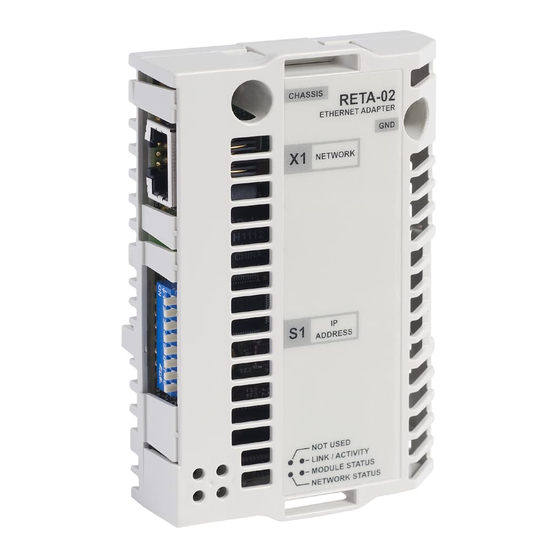
Side view Figure 1. The RETA-02 Adapter module. Compatibility The RETA-02 is compatible with all master stations that support the Modbus/TCP. PROFINET IO can be used with master stations that support PROFINET IO and sub-slots. Functionality of the RETA-02 is limited if master station doesn’t support multiple sub- slots per slot. -
Page 18: Warranty And Liability Information
(12) months after installation or twenty-four (24) months from date of manufacturing, whichever first occurs. The local ABB office or distributor may grant a warranty period different to the above and refer to local terms of liability as defined in the supply contract. -
Page 19: Quick Start-Up Guide
WARNING! Follow the safety instructions given in this manual and the Hardware Manual of the drive. Mechanical installation • Insert the RETA-02 into its specified slot in the drive (SLOT2 for ACS550, SLOT1 for ACS800). • Fasten the two screws. -
Page 20: Network Configuration
With an ACS550 drive, set parameter 98.02 COMM PROT SEL to EXT FBA. With an ACS800, set parameter 98.02 COMM. MODULE LINK to FIELDBUS and parameter 98.07 COMM PROFILE to ABB DRIVES or GENERIC according to the selected communication protocol and profile. -
Page 21: Communication
PROFINET IO configuration Install the RETA-02 GSDML file (e.g. GSDML-V2.0-ABBDrives- RETA02-yyyymmdd.xml, where yyyy = year, mm = month, dd = day of the month when the file was created) and after that update the device catalog. - Page 22 RETA-02 Vendor and PROFIdrive objects should be available in the product catalog. Figure 3. Product catalog Example 1: PLC configuration in Vendor mode PPO 6 consists of 10 input and output parameters. Eight of the inputs and outputs are freely configurable parameters. The first four of them can be mapped either with the bus configuration parameters or the initial record data of the PLC.
- Page 23 • Drag-and-drop the RETA-02 Vendor object from the device catalog to the PROFINET-IO-System. Also drag-and-drop the Vendor Object PPO 6 to slot one. Figure 4. Adding RETA-02 Vendor object to configuration • Right click the device object and open the Object Properties menu.
- Page 24 • Assign device name. Figure 6. Menu selection for assigning the device name • Set Bus Configuration parameters as the source for the input and output parameters 1-4 through the Properties menu of the Vendor Object PPO6. Configure the last four inputs and outputs. If Stop Action selection is set to Fail-safe values configure them as well.
- Page 25 REQUEST 11.03 EXT1 REF1 SELECT COMM.REF 16.04 FAULT RESET SEL COMM.CW 98.02 COMM. MODULE LINK FIELDBUS 98.07 COMM PROFILE ABB DRIVES 51.01 MODULE TYPE PROFINET IO 51.02 COMM RATE 0 (Auto-negotiation) 51.03 DHCP 0 (Disabled) 51.04 - 51.07 IP ADDRESS 10.0.0.6...
- Page 26 4.01. To include more inputs and outputs without changing the telegram structure different number of PZD’s (process data) can be added. The notation used here is ABB specific. In this example, standard telegram 1 and four inputs and outputs are configured with the initial record data.
- Page 27 Figure 9. Properties menu of the Standard Telegram 1 • Mapping of the inputs and outputs has to be done through the Properties menu of the corresponding PZD. Input 1 could be for example 103 (Frequency). Figure 10. Properties menu of a PZD •...
- Page 28 changed through the configuration parameters unless parameter 26 is set to 1 (Bus configuration parameters). Table 3. ACS550 parameter settings with Std Telegram 1 + 4 PZD Drive parameter Example setting for ACS550 10.01 EXT1 COMMANDS COMM 10.03 DIRECTION REQUEST 11.03 REF1 SELECT COMM 16.04 FAULT RESET SEL...
-
Page 29: Mechanical Installation
Hardware Manual. Mounting The RETA-02 is to be inserted into its specific position in the drive. The module is held in place with plastic retaining clips and two screws. The screws also provide the earthing of the CAT 5 STP cable shield connected to the module, and interconnect the GND signals of the module and the control board of the drive. - Page 30 Mechanical installation...
-
Page 31: Electrical Installation
Ethernet connection The network cable is connected to the RJ45 connector (X1) on the RETA-02 module. Standard CAT 5 UTP and CAT 5 STP (recommended) cables can be used. In case CAT 5 STP is used, the cable shield is connected via rc filter to drive frame through the module. - Page 32 Electrical installation...
-
Page 33: Drive Configuration
ABB drives can receive control information from multiple sources including digital inputs, analogue inputs, the drive control panel and a communication module (e.g. RETA-02). ABB drives allow the user to separately determine the source for each type of control information (Start, Stop, Direction, Reference, Fault Reset, etc.). - Page 34 Table 4. The RETA-02 configuration parameters Par. Parameter name Alternative settings Default setting MODULE TYPE (Read-only) PROFINET IO Comm rate (0) Auto-negotiate; (1) 100 Mbit/s, (0) Auto-negotiate full duplex; (2) 100 Mbit/s, half duplex; (3) 10 Mbit/s, full duplex; (4) 10 Mbit/s, half duplex DHCP (0) DHCP disabled;...
- Page 35 Input 2 0…65535 Input 3 0…65535 Input 4 0…65535 In/Out 1-4 src (0) Initial record data; (1) Bus configuration parameters; (2) Disable Drive configuration...
- Page 36 1 MODULE TYPE This parameter shows the module type as detected by the drive. The value cannot be adjusted by the user. If this parameter is undefined, the communication between the drive and the module has not been established. 2 Comm rate Defines the baud rate for the Ethernet interface.
- Page 37 4 IP address 1 5 IP address 2 6 IP address 3 7 IP address 4 An IP address is assigned to each TCP/IP node on an Ethernet network. IP addresses consist of four decimal integers in the range of 0…255 separated by periods, each integer representing the value of one byte (8 bits, octet) in the IP address.
- Page 38 16 Protocol Selects the application protocol and communication profile for the network communication. 0 = Modbus/TCP 1 = PROFINET IO 17 Modbus timeout The Modbus protocol does not have an implementation for time- out on application layer and this may be required when controlling a drive.
- Page 39 Output Output 1 PZD3 Output 2 PZD4 … … Output 8* PZD10 *Outputs from 4 to 10 are defined separately in the PLC. The contents are defined by a decimal number in the range of 0 to 65535 as follows: Not used 1…99 Data set area of the drive...
- Page 40 that are updated more frequently. Reading from the Modbus/TCP register corresponding to the parameter is faster. When PROFINET IO protocol is in use, these parameters define the input (from drive to master) data words or drive parameters that can be used with the vendor specific PPO’s or in addition to the Standard telegram 1 (see chapter Communication).
- Page 41 PROFINET IO is used. User can map parameters to the first four inputs and outputs with the initial record data of the IO controller or by using the RETA-02 configuration parameters described above. Initial record data has a parameter that can be used to select the source in similar way.
- Page 42 Drive configuration...
-
Page 43: Network Configuration
Network configuration Overview RETA-02 supports 10 Mbit/s and 100 Mbit/s data transfer rates and automatically detects the data transfer rate used in the network. Note: PROFINET IO uses only 100 Mbit/s in Full-duplex mode. The network configuration of the RETA-02 can be done using several methods. -
Page 44: Ip Settings Configuration
IP settings configuration Start switches DHCP? = 0? DHCP Wait for config Bus config through Gleaning or server parameters DCP protocols timeout? <> 0? Use 192.168.0.xxx Use configuration Use stored Configuration (xxx = DIP setting) from DHCP server settings received? Network configuration... - Page 45 Method Description Note DIP switch By default, the IP address is defined by Only read at (S1) software. Setting any DIP actuator to ON start-up. enables hardware selection. DIP actuators Only for intranet 1 to 8 define the last octet (1 to 254) of the use.
- Page 46 Method Description Note Settings stored Use the configuration stored in the RETA-02 RETA-02 must in RETA-02 configuration parameters. See Table 4. be started for configuration chapter Drive configuration. parameters configuration changes to take effect. Gleaning Change the IP address from a PC using the...
-
Page 47: Profinet Io And Dcp
Duplicate IP address detection RETA-02 has a duplicate IP address detection mechanism when using Modbus/TCP. If the module detects another device on the network, which has the same IP address, it lids the Network status led in red and starts to blink the Module status led in red. - Page 48 Network configuration...
-
Page 49: Master Configuration
Configuration of the master station requires a type definition (GSD) file. In PROFINET IO the GSD file is written in XML based language called GSDML. RETA-02 has a GSD file, which is available from www.profinet.com, www.abb.com or your local ABB representative. - Page 50 Master configuration...
-
Page 51: Communication Profiles
Communication profiles are ways of conveying control commands (Control word, Status word, references and actual values) between the master station and the drive. With the RETA-02 module, the PROFINET IO network may employ either the PROFIdrive profile or the ABB Drives profile. -
Page 52: The Profidrive Communication Profile
ABB drives can receive control information from multiple sources including analogue and digital inputs, the drive control panel and a communication module (e.g. RETA-02). In order to have the drive controlled through PROFINET IO, the communication module must be defined as the source for control information, e.g. - Page 53 Scaling The speed reference (REF) in hexadecimal (0 … 4000h) corresponds to 0 … 100% of Nominal Speed or Maximum Reference depending on the drive type. ABSOLUTE LIMIT or 1.63×0×4000 NOMINAL REF1: 0×4000 REF1: 0×4000 REF×MIN REF1: 0=REF×MIN Reference Reference range for range for REF1: 0=0...
-
Page 54: Actual Values
Actual values Actual values are 16-bit words containing information on the operation of the drive. The functions to be monitored are selected by a drive parameter. Scaling The actual speed (ACT) in hexadecimal (0 … 4000h) corresponds to 0 … 100% of Nominal Speed or Maximum Reference depending on the drive type. - Page 55 Table 5. The Control Word for the PROFIdrive communication profile. The upper case boldface text refers to the states shown in Figure 11. Bit Name Value Proceed to STATE/Description 0 ON Proceed to READY TO OPERATE. OFF1 Emergency OFF, stop by the selected deceleration ramp. Proceed to OFF1 ACTIVE;...
- Page 56 Bit Name Value Proceed to STATE/Description 0 ⇒ 1 Fault reset if an active fault exists. Proceed to SWITCH- 7 RESET ON INHIBIT. Note: This bit is effective only if the fieldbus interface is set as the source for this signal by drive parameters. (Continue normal operation) 8 INCHING_1 Inching 1.
- Page 57 Table 6. The Status Word for the PROFIdrive communication profile. The upper case boldface text refers to the states shown in Figure 11. Bit Name Value STATE/Description RDY_ON READY TO SWITCH ON. NOT READY TO SWITCH ON. RDY_RUN READY TO OPERATE. OFF1 ACTIVE.
- Page 58 Bit Name Value STATE/Description Drive specific Communication profiles...
-
Page 59: State Machine
SWITCH-ON MAINS OFF INHIBIT (SW Bit6=1) PROFIdrive OFF1 (CW Bit0=0) Power ON State Machine NOT READY CW = Control Word TO SWITCH ON (SW Bit0=0) A B C D SW = Status Word = Speed = Input Current (CW=xxxx xxxx xxxx x110) RFG = Ramp Function (CW Bit3=0) Generator... -
Page 60: The Abb Drives Communication Profile
ABB drives can receive control information from multiple sources including analogue and digital inputs, the drive control panel and a communication module (e.g. RETA-02). In order to have the drive controlled through the fieldbus, the module must be defined as the source for control information, e.g. - Page 61 Scaling References are scaled as shown below. Note: The values of REF1 MAX and REF2 MAX are set by drive parameters. See the drive documentation for further information. ABSOLUTE LIMIT or 1.63×20000 REF1: 20000 REF1: 20000 REF×MAX REF2: 10000 REF2: 10000 REF×MIN REFx: 0=REF×MIN Reference...
-
Page 62: Actual Values
Actual values Actual values are 16-bit words containing information on the operation of the drive. The functions to be monitored are selected by a drive parameter. Scaling Actual values are scaled as shown below. Note: The values of REF1 MAX and REF2 MAX are set by drive parameters. -
Page 63: Communication
Table 7. The Control Word for the ABB Drives communication profile. The upper case boldface text refers to the states shown in Figure 11. Name Value STATE/Description OFF1_ Proceed to READY TO OPERATE. CONTROL Stop along currently active deceleration ramp. -
Page 64: Communication
Name Value STATE/Description RAMP_HOLD Enable ramp function. Proceed to RAMP FUNCTION GENERATOR: ACCELERATOR ENABLED. Halt ramping (Ramp Function Generator output held). RAMP_IN_ Normal operation. Proceed to OPERATING. ZERO Note: This bit is effective only if the fieldbus interface is set as the source for this signal by drive parameters. -
Page 65: Communication
Table 8. The Status Word for the ABB Drives communication profile. The upper case boldface text refers to the states shown in Figure 12. Name Value STATE/Description RDY_ON READY TO SWITCH ON. NOT READY TO SWITCH ON. RDY_RUN READY TO OPERATE. -
Page 66: Communication
Name Value STATE/Description ABOVE_ Actual frequency or speed equals or exceeds LIMIT supervision limit (set by drive parameter). Valid in both directions of rotation. Actual frequency or speed within supervision limit. EXT_CTRL_ External Control Location EXT2 selected. External Control Location EXT1 selected. 13 to Reserved. - Page 67 (CW Bit5=0) (CW=xxxx x1xx xxx1 1111) RFG: OUTPUT ENABLED (CW Bit6=0) (CW=xxxx x1xx xx11 1111) RFG: ACCELERATOR state ENABLED condition (CW=xxxx x1xx x111 1111) rising edge OPERATION the bit (SW Bit8=1) Figure 12. State machine, ABB Drives communication profile Communication profiles...
-
Page 68: Communication
Communication profiles... -
Page 69: Communication
This chapter describes the Modbus/TCP and PROFINET IO messaging used in the communication with the drive. Protocols The RETA-02 module supports the Modbus/TCP protocol according to Modbus/TCP Specification 1.0, and the PROFINET IO protocol. Protocol can be selected with a parameter PROTOCOL. -
Page 70: Modbus/Tcp
Modbus/TCP Register read and write The drive parameter and data set information is mapped into a 4xxxx register area. This holding register area can be read from an external device, and an external device can modify the register values by writing to them. There are no set-up parameters for mapping the data to the 4xxxx register area. - Page 71 Table 9.Parameter mapping Parameter 4GGPP Data sets 40001…40096 00 Data sets 01 Data word 1.1 02 Data word 1.2 03 Data word 1.3 Each data set consists 04 Data word 2.1 of 3 data words. For 05 Data word 2.2 example, ‘Data word 06 Data word 2.3 2.3’...
- Page 72 Address does not exist or is read/write- address protected Illegal data Value is outside minimum and maximum value limits. Parameter is read-only Function codes The RETA-02 supports the Modbus function codes shown below. Table 11.Supported function codes Function Name Description Modbus code class...
-
Page 73: Profinet Io
PROFINET IO Overview This chapter describes the PROFINET IO communication protocol for RETA-02. For detailed information on PROFINET IO communication, refer to PROFINET specification Application Layer protocol for decentralized periphery and distributed automation v2.0. Introduction to PROFINET IO PROFINET IO is a fieldbus protocol that enables communication between programmable controllers and distributed field devices in Ethernet network. -
Page 74: Profinet Io In Reta-02
(DAP) and functional module with the tool as well. RETA-02 uses slots 0 and 1. Slot 0 doesn’t have any sub-slots and the DAP module attached to it represents the device itself. Other functional modules and sub-modules, which are described in the GSD file can be assigned to slot 1 and its sub-slots. -
Page 75: Cyclic Messaging In Vendor Mode
PROFIdrive profile-specific parameters for more information. Cyclic messaging in Vendor mode In vendor mode the drive can be controlled according to ABB Drives communication profile. PPO types The adapter has three different PPO types, which differ only by the amount of freely configurable inputs and outputs. -
Page 76: Cyclic Messaging In Profidrive Mode
Cyclic messaging in PROFIdrive mode Standard telegram 1 RETA-02 supports Standard telegram 1. It is possible to add inputs and outputs as separate PZD’s. GSD file contains special collections where standard telegram 1 has been extended with inputs and outputs. - Page 77 Parameter response A write request is first sent containing the parameter request. If the write request is valid, the RETA-02 acknowledges it with request accepted. The master should then send a read request. If the RETA-02 is still busy performing the internal parameter request, it will return a negative response with the error code 0xB5 (State conflict).
- Page 78 Note: In IEC 61131-3 compatible systems function blocks are provided for accessing data non-cyclically. In Siemens S7, SFB 52 "RDREC" can be used for reading and SFB53 "WRREC" for writing Data Records. RDREC WRREC BOOL --- REQ VALID --- BOOL BOOL --- REQ DONE --- BOOL DWORD...
- Page 79 User Specific Record Data User Specific Record Data can be used for global parameter access. This index is supported for compatibility reasons. Header and frame structures PROFINET IO uses DCE RPC (Distributed Computing Environment Remote Procedure Call) protocol for acyclic read and acyclic write services.
- Page 80 Table 14. Response error codes Byte Value and meaning ErrorCode 0xDF (Error Write) 0xDE (Error Read) ErrorDecode 0x80 (PNIORW) ErrorCode1 decoded according to Table 15. ErrorCode2 is ‘0’. 0x81 (PNIO) ErrorCode1 and ErrorCode2 decoded according to Table 15. ErrorCode1 Error class and error code (see Table 15.
- Page 81 Table 15. ErrorCode1 with PNIORW decoding Error class Meaning Error code 0 … 9 (Reserved) 10 (0x0A) Application 0 = Read error 1 = Write error 2 = Module failure 3 … 7 = Reserved 8 = Version conflict 9 = Feature not supported 10 …...
- Page 82 unique identifiers for the connection, addressing information and length of the record data. The response also contains two additional fields for transferring information. See Table 16. details. Table 16.Structure of the Read and Write blocks Field(s) Description Range Type Service Request or Response Request (0x00) service.
- Page 83 Additional Field for transferring UI16 value 1 additional data (response only) Additional Field for transferring UI16 value 2 additional data (response only) Padding 24 bytes for request, 20 bytes for response. Data block Used only with write request and read response. Data block contains PROFIdrive specific request or response header.
- Page 84 Address of the PROFIdrive 1 … 65535 Word Index parameter that is being accessed. (group) Also "0" is allowed by RETA-02. Parameter group of the drive when accessing drive parameters. Subindex Addresses the first array element 0 … 65535 Word...
- Page 85 Values* The values of the request. In case – of odd number of bytes, a zero Format byte is appended to ensure the field word structure of the telegram. *Only if Request ID is 0x02 (Change Parameter). The Format, Number of Values and Values fields are repeated for other parameters.
- Page 86 Table 18. PROFIdrive Response header Field(s) Description Range Response Mirrored from the request. 1 … 255 Reference Response Response from the slave. In case Request Param OK (0x01) any requested services fail, a “not Request Param NAK (0x81) acknowledged” (NAK) response will Change Param OK (0x02) be indicated.
- Page 87 Table 20. PROFIdrive Parameter Request error codes Error # Meaning Used at 0x00 Impermissible parameter Access to unavailable parameter number 0x01 Parameter value cannot be Change access to a parameter value changed that cannot be changed 0x02 Low or high limit exceeded Change access with value outside the limits 0x03...
- Page 88 0x16 Parameter address Illegal value or value that is not impermissible supported for the attribute, number of elements, parameter number or sub- index, or a combination 0x17 Illegal format Write request: Illegal format or format of parameter data that is not supported 0x18 Number of values inconsistent Write request: Number of values of...
-
Page 89: Parameter Data Transfer Examples
Parameter data transfer examples The following example shows how parameter data is transferred using the acyclic parameter access mechanism’s READ and WRITE. Note: Only the part of the acyclic frame is presented in the examples. The padding zeroes are not presented. Example 1: Reading a drive parameter To determine the parameter number and subindex for drive parameter reading, multiply the parameter number by one... -
Page 90: Identification And Maintenance Functions (I&M)
The purpose of the I&M functions is to provide support for the customer during commissioning, parametrization and repair of the module. RETA-02 supports I&M functions 0 - 4, which can be accessed with a qualified configuration tool (like DTM Tool) or using the Record data object’s read request. - Page 91 Function Record Data Index I&M 0 0xAFF0 I&M 1 0xAFF1 I&M 2 0xAFF2 I&M 3 0xAFF3 I&M 4 0xAFF4 Structure of the I&M functions is described in the following tables. Communication...
- Page 92 I&M0 Device identification (read-only) Content Size Description Header 10 bytes Vendor ID 2 bytes PROFINET Vendor ID of ABB, which is 26 (0x001A) Order ID 20 bytes Order number of the RETA-02 adapter kit Serial number 16 bytes Serial number of the adapter...
-
Page 93: Profidrive Profile-Specific Parameters
I&M3 Additional data Content Size Description Header 10 bytes DESCRIPTOR 54 bytes Any additional data set by the user I&M4 Signature Content Size Description Header 10 bytes SIGNATURE 54 bytes Security code for identifying sessions and changes PROFIdrive profile-specific parameters PROFIdrive parameters contain data of the drive in standard form. - Page 94 Para- Mode Data type Description meter Unsigned16 Control rights (process data, PZD). Value Mode No control through the PROFINET IO. Setpoint telegram not used. IO-controller will control the drive through IO data (default) IO-supervisor will control the drive through parameters 900 and 907 (Not supported at) Unsigned16 Selection switch for operating mode.
- Page 95 Para- Mode Data type Description meter Array [64] Fault number. (coded according to Unsigned16 DRIVECOM profile) Subindex Contents See parameter 945. Array [n] Fault time TimeDifference Unsigned16 Number of faults occured. Writing a zero clears the value. Unsigned16 **Last alarm Unsigned16 **Second last alarm Unsigned16...
- Page 96 Para- Mode Data type Description meter Unsigned16 Software reset Value Description No action Power-cycle PROFINET IO module The parameter must do a zero-to-one transition and the motor must be stopped. Array [8] Drive Object identification Unsigned16 Subindex Contents Manufacturer DO type Version Firmware date (year) Firmware date...
-
Page 97: Diagnostic And Alarm Mechanism
*** Supported in Vendor mode and/or PROFIdrive operating mode Diagnostic and alarm mechanism RETA-02 has mechanisms for sending alarms and saving diagnostics data to fault buffer. Alarm will be triggered if the host or drive has faults in communication or operation. There are three... - Page 98 * Channel Error Type is PROFIdrive profile specific. See list of Channel Error Types in the table below. Alarm mechanism When a fault situation occurs the RETA-02 adapter will send an alarm notification (see table below), which the master station has to acknowledge. Alarm notifications can be acknowledged, viewed and handled with e.g.
- Page 99 Table 22. Channel Error types Corresponding ChannelError Abbreviation Description DRIVECOM fault Type numbers* 0x9000 MICRO_HW Microcontroller 6000, 6010, 6100, 6306- hardware or software 630F, 6320 0x9001 MAINS Mains supply 3210, 3211 0x9002 LOW_VOLT Low voltage supply 3130, 3220 0x9003 DC_OVERV DC link overvoltage 0x9004 POWER_ELEC Power electronics...
-
Page 100: Fault Buffer Mechanism
Fault buffer mechanism PROFIdrive profile has a mechanism that can store eight fault situations to PROFIdrive parameters. Fault and diagnostic data, like fault number, fault code and fault time can be accessed simultaneously with only one subindex. The mechanism consists of six PROFIdrive parameters: •... - Page 101 PNU947 PNU945 PNU948 Fault Fault code Fault time Sub- number index 0×4210 0×9005 TimeX Actual fault situation n 0×7510 0×900B TimeY Fault situation … … … … … … … … … … … … … … … … Fault situation Figure 13.
- Page 102 Figure 13. illustrates the structure of a fault buffer. The fault buffer is composed of four parameters, fault number (PNU 947), fault code (PNU 945), fault time (PNU 948) and fault value (PNU 949). The rows of the fault buffer are represented by the parameter sub- indices.
-
Page 103: Led Indications
Diagnostics LED indications The RETA-02 module is equipped with three diagnostic LEDs. The description of the LEDs in Modbus/TCP is presented below. (not used) Link/Activity Network Status Module Status Name Colour Function Off - Module cannot detect a link Flashing green - Module is receiving/transmitting... - Page 104 The description of the LEDs in PROFINET IO is presented below. (not used) Link/Activity Network Status Module Status Name Colour Function Off - Module cannot detect a link Flashing green - Module is receiving/transmitting Green on Ethernet Steady green - Module has detected a link Off - No connection with IO-controller Flashing green (pattern 1) - Connection with IO- Red/...
-
Page 105: Led Patterns
Led patterns Pattern 1 (ms) 1000 Pattern 2 (ms) 1000 1250 1500 Pattern 3 (ms) 1000 1250 1500 1750 2000 Pattern 4 (ms) 1000 1250 1500 1750 2000 2250 2500 Pattern 5 (ms) 1000 1250 1500 1750 2000 2250 2500 2750 3000 Diagnostics... - Page 106 Diagnostics...
-
Page 107: Definitions And Abbreviations
Definitions and abbreviations PROFINET IO definitions Acyclic Communication in which messages are sent only once Communication on request Array Parameter consisting of data fields of equal data type Broadcast Non-acknowledged message from master to all bus participants (compare Multicast) Command Word See Control Word Communication Any object of a real device that can be communicated... - Page 108 Name Symbolic name of a parameter Nibble Set of 4 bits Object Dictionary Local storage of all Communication Objects recognised by a device Object List List of all accessible objects Parameter Value that can be accessed as Object, e.g. variable, constant, signal Parameter Number Parameter address...
-
Page 109: Technical Data
Technical data RETA-02 Enclosure: 34 mm CHASSIS RETA-01 PROFIBUS ADAPTER NETWORK ADDRESS NOT USED LINK / ACTIVITY MODULE STATUS NETWORK STATUS 62 mm Mounting: Into the option slot on the control board of the drive. Degree of protection: IP20 Ambient conditions: The applicable ambient conditions specified for the drive in its Hardware Manual are in effect. -
Page 110: Ethernet Link
Connectors: • 34-pin parallel bus connector • RJ-45 connector Current consumption: • 380 mA average (5 V), supplied by the control board of the drive General: • Estimated min. lifetime: 100 000 h • All materials UL/CSA-approved • Complies with EMC standards EN 50081-2 and EN 50082-2 Ethernet link Compatible devices: Ethernet standard IEEE 802.3 and 802.3u devices... - Page 112 ABB Oy ABB Inc. ABB Beijing Drive Systems AC Drives Automation Technologies Co. Ltd. P.O. Box 184 Drives & Motors No. 1, Block D, FIN-00381 HELSINKI 16250 West Glendale Drive A-10 Jiuxianqiao Beilu FINLAND New Berlin, WI 53151 Chaoyang District Telephone +358 10 22 11 Beijing, P.R.