Table of Contents
Advertisement
Quick Links
Advertisement
Table of Contents

Related Manuals for ABB RECA-01


Summary of Contents for ABB RECA-01
- Page 1 ABB Drives User’s Manual EtherCAT® Adapter Module RECA-01...
- Page 2 EtherCAT® is registered trademark and patented technology, licensed by Beckhoff Automation GmbH, Germany.
- Page 3 EtherCAT® Adapter Module RECA-01 User’s Manual 3AUA0000043520 REV B EFFECTIVE: 2010-04-23 © 2010 ABB Oy. All Rights Reserved.
-
Page 5: Safety Instructions
Safety instructions What this chapter contains This chapter states the general safety instructions that must be followed when installing and operating the RECA-01 EtherCAT® Adapter module. The material in this chapter must be studied before attempting any work on the unit. - Page 6 Safety instructions...
-
Page 7: Table Of Contents
EtherCAT ........... 15 RECA-01 EtherCAT® Adapter module ......15 Compatibility . - Page 8 RECA-01 configuration ........
- Page 9 Actual value of the DSP 402 profile ....... 39 ABB Drives communication profile ....... . 39 The control word and the status word .
- Page 10 RECA-01 ........
-
Page 11: Introduction
RECA-01 EtherCAT® Adapter module. Intended audience The manual is intended for people responsible for commissioning and using an RECA-01 EtherCAT® Adapter module. The reader is expected to have a basic knowledge of electrical fundamentals, electrical wiring practices and how to operate the drive. - Page 12 Overview contains a short description of the EtherCAT® protocol and the RECA-01 EtherCAT® Adapter module, a delivery checklist, and information on the manufacturer’s warranty. Quick start-up guide contains a short description of how to set up the RECA-01 EtherCAT® Adapter module.
-
Page 13: Terms Used In This Manual
RECA-01 CANopen Adapter module The RECA-01 CANopen Adapter module is one of the optional fieldbus adapter modules available for ABB drives. The RECA-01 is a device through which an ABB drive is connected to an EtherCAT® network. Parameter A parameter is an operating instruction for the drive. Parameters can be read and programmed with the drive control panel, or through the RECA-01 module. -
Page 14: Product And Service Inquiries
Product and service inquiries Address any inquiries about the product to your local ABB representative, quoting the type code and serial number of the unit in question. A listing of ABB sales, support and service contacts can be found by navigating to www.abb.com/drives and selecting Drives –... -
Page 15: Overview
(www.ethercat.org). RECA-01 EtherCAT® Adapter module The RECA-01 EtherCAT® Adapter module is an optional device for ABB drives which enables the connection of the drive to an EtherCAT® network. Through the RECA-01 EtherCAT® Adapter module it is possible to Overview... - Page 16 See the drive manuals for module placement options. The module is classified as a full EtherCAT® slave. Device Description files for ABB Drives are available through your local ABB representative and the ABB Library (www.abb.com). Ethernet connector X1...
-
Page 17: Compatibility
Compatibility The RECA-01 module is compatible with all master stations that support the EtherCAT® protocol. Delivery check The option package for the RECA-01 EtherCAT® Adapter module contains: • EtherCAT® Adapter module, type RECA-01 • two screws (M3x10) • this manual. - Page 18 If you have any questions concerning your ABB drive, please contact the local distributor or ABB office. The technical data, information and specifications are valid at the time of printing.
-
Page 19: Quick Start-Up Guide
WARNING! Follow the safety instructions given in this manual and the Hardware Manual of the drive. Mechanical installation • Insert the RECA-01 into its specified slot in the drive (SLOT2 for ACS550, SLOT1 for ACS800). • Fasten the two screws. -
Page 20: Drive Configuration
• Verify that the drive parameter group 51 is activated and that parameter 51.01 FBA TYPE is ETHERCAT. • Select either ABB Drives or DSP 402 communication with parameter 51.02. In ACS800, also set parameter 98.07 COMM PROFILE to ABB DRIVES or GENERIC (DSP 402). -
Page 21: Master System Configuration
98.07 COMM PROFILE GENERIC Master system configuration This section guides the user to configure the RECA-01 module in the EtherCAT® network using Beckhoff's TwinCAT System Manager. If you are using another master system, consult its manual for information on configuring the network. - Page 22 TxPDO 6 to the input assignment (0x1C13) and the default RxPDO 6 to the output assignment (0x1C12). • If you are using the ABB drives profile, assign the default TxPDO 21 to the input assignment (0x1C13) and the default RxPDO 21 to the output assignment (0x1C12).
- Page 23 Figure 3. Configuring process data in TwinCAT • The configuration will be transferred to the module when its state is changed from Pre-operational to Safe-operational. It might also be necessary to reload I/O devices (by pressing F4) in TwinCAT to apply the changes. Quick start-up guide...
- Page 24 Quick start-up guide...
-
Page 25: Mechanical Installation
Mounting The RECA-01 module is to be inserted into its specific position in the drive. The module is held in place with plastic retaining clips and two screws. The screws also provide the earthing of the... - Page 26 Mechanical installation...
-
Page 27: Electrical Installation
EtherCAT® connections The network cables can be connected to the two RJ45 connectors (X1 and X2) on the RECA-01 module. Standard CAT 5 UTP, CAT 5 FTP or CAT 5 STP cables can be used. In case CAT 5 STP is used, the cable shield is internally connected to the drive frame through the module. - Page 28 Electrical installation...
-
Page 29: Drive Configuration
Normally, a parameter must be adjusted to activate the communication. Please refer to the drive documentation. As communication between the drive and the RECA-01 is established, several configuration parameters are copied to the drive. These parameters must be checked first and adjusted if... -
Page 30: Module Type
If this parameter is undefined, the communication between the drive and the module has not been established. 2 TRANSPARENT/PROFILE MODE This parameter is used for choosing either the transparent (ABB Drives) or the DSP 402 communication profile. This selection can also be changed with CoE object 0×2400 (hex). -
Page 31: Master Configuration
Device Description Files are XML files that specify the properties of the slave device for the EtherCAT® master. The description files contain information on the supported communication objects. Device Description Files for ABB Drives are available through your local ABB representative and the ABB Library (www.abb.com). Master configuration... - Page 32 Master configuration...
-
Page 33: Communication Profiles
(Control word, Status word, references and actual values) between the master station and the drive. With the RECA-01 module, the either master may employ either the CANopen DSP 402 (Device Profile Drives and Motion Control) profile or the ABB Drives profile. The Control Word, Status Word, references and actual values of these profiles are described in the following sections. -
Page 34: Supported Mode Of Operation
The DSP 402 profile offers a choice of several modes of operation. These modes define the operation of the drive. RECA-01 supports Velocity mode, which is a basic operation mode used to control the velocity of the drive. Control Word and Status Word of the DSP 402 profile... - Page 35 Name Value Description Ramp function Ramp function generator input value is set generator use ref. to zero. Normal operation: Ramp function generator input is the ramp reference. Fault reset The functionality of bits 0…3 and 7 are described in table Operation of bits 0…3 and 7 of the DSP 402 Control Word.
- Page 36 ** When Control Word bit 3 (Enable operation) is 1, the drive does not stay in the SWITCHED ON state, but immediately transitions to state OPERATION ENABLED. Status Word of DSP 402 Name Value Description Ready to switch ON Not ready to switch ON Ready to switch ON Switched ON Not switched ON...
- Page 37 Name Value Description 12…13 Reserved Drive specific ACx550: External control location EXT1 selected ACx550: External control location EXT2 selected ACS800: User settable* Drive specific ACx550: Not used ACS800: User settable* * The functionality of the vendor-specific bits in ACS800 can vary according to the control program.
- Page 38 from any state CW: Control Word FAULT REACTION START SW: Status Word ACTIVE SW: xxxxxxxxx0xx1111 Power-on, Fault reaction State transition self-initialisation completed NOT READY FAULT TO SWITCH ON SW: xxxxxxxxx0xx0000 SW: xxxxxxxxx0xx1000 Initialised CW: xxxxxxxx1xxxxxxx (15) successfully SWITCH-ON DISABLED SW: xxxxxxxxx1xx0000 CW: xxxxxxxx0xxxx110 CW: xxxxxxxx0xxxx01x CW: xxxxxxxx0xxxxx0x...
-
Page 39: Reference Of The Dsp 402 Profile
Vl dimension factor object (CoE object 0x604C hex): Drive actual speed = Control effort * Vl dimension factor The scaling is 1 by default. ABB Drives communication profile The control word and the status word The Control Word is the principal means for controlling the drive from a fieldbus system. -
Page 40: Control Word And Status Word Of The Abb Drives Profile
State machine, ABB Drives communication profile page 44). The ABB Drives profile Control Word can be found in CoE object 0x2005 (hex) (Transparent Control Word) and the Status Word in CoE object 0x2007 (hex) (Transparent Status Word). Control Word and Status Word of the ABB Drives profile The following table presents the Control Word of the ABB Drives communication profile. - Page 41 Control Word of ABB Drives profile Name Value STATE/Description INHIBIT_ Proceed to OPERATION ENABLED. OPERATION Note: Run enable signal must be active; see the drive manuals. If the drive is set to receive the Run enable signal from the fieldbus, this bit activates the signal.
- Page 42 12 to Reserved The following table presents the Status Word of the ABB Drives communication profile. The upper case boldface text refers to the states shown in figure State machine, ABB Drives communication...
- Page 43 Status Word of the ABB Drives profile Name Value STATE/Description OFF_2_STA OFF2 inactive OFF2 ACTIVE OFF_3_STA OFF3 inactive OFF3 ACTIVE SWC_ON_ SWITCH-ON INHIBITED INHIB – ALARM Warning/Alarm No warning/alarm OPERATING. Actual value equals reference = is SETPOINT within tolerance limits, i.e. in speed control, speed error is 10% max.
- Page 44 (CW Bit5=0) (CW=xxxx x1xx xxx1 1111) RFG: OUTPUT ENABLED (CW Bit6=0) (CW=xxxx x1xx xx11 1111) RFG: ACCELERATOR state ENABLED condition (CW=xxxx x1xx x111 1111) rising edge OPERATION the bit (SW Bit8=1) Figure 5. State machine, ABB Drives communication profile Communication profiles...
-
Page 45: References
ABB drives can receive control information from multiple sources including analogue and digital inputs, the drive control panel and a communication module (e.g. RECA-01). In order to have the drive controlled through the fieldbus, the module must be defined as the source for control information, e.g. -
Page 46: Actual Values
Actual values are 16-bit words containing information on the operation of the drive. The functions to be monitored are selected by a drive parameter. The ABB Drives profile actual values can be found in CoE objects 0x2008 (hex) (Transparent Actual Value) and 0x4000 (hex), subindex 6 (Actual Value 2). -
Page 47: Communication
Communication What this chapter contains This chapter describes the communication on an EtherCAT® network. EtherCAT® frame structure In EtherCAT, the data between the master and the slaves is transmitted in Ethernet frames. An EtherCAT® Ethernet frame consists of one or several EtherCAT® telegrams, each addressing individual devices and/or memory areas. -
Page 48: Ethercat® Services
EtherCAT® Services EtherCAT® specifies services for reading and writing data from the physical memory within the slaves. RECA-01 supports the following EtherCAT® services: • Auto increment physical read (APRD) • Auto increment physical write (APWR) • Auto increment physical read write (APRW) •... -
Page 49: Logical Addressing
Each FMMU configuration contains a logical start address, a physical memory start address, a bit length and a type that specifies the direction of the mapping (input or output). RECA-01 has four FMMUs. The EtherCAT® master can use them for any purpose. Sync managers Sync managers control the access to the application memory. -
Page 50: Sync Manager Channel 3
Sync manager 3 is used for process input data. It contains the Tx PDOs specified by the PDO assignment object 0x1C13 (hex). Watchdogs The RECA-01 module provides two watchdogs, with which the functionality of the module and connection can be monitored. The watchdogs are configured and enabled by the EtherCAT® master. -
Page 51: Canopen Over Ethercat® (Coe)
CANopen DS 301 communication profile and is called CANopen over EtherCAT, or CoE. The protocol specifies the Object Dictionary in the module, as well as communication objects for exchanging process data and acyclic messages. RECA-01 implements the following message types: Communication... -
Page 52: Process Data Objects (Pdo)
Words, References and Actual Values, but most CoE dictionary objects and drive parameters can be mapped for cyclical communication. RECA-01 has three receive PDOs and three transmit PDOs. Each PDO can have 0…8 application objects mapped inside it. The default mappings for the PDOs are described in tables... - Page 53 In EtherCAT, the PDOs are transported inside Sync Manager Channel objects. RECA-01 has two sync manager channels for process data: SM 2 for output data (Rx data) and SM 3 for input data (Tx data). Changing the Sync manager PDO assignments is only possible in the pre-operational state.
-
Page 54: Service Data Objects (Sdos)
SDO services and SDO Information services: SDO services provide read/write access to the entries in the device CoE Object Dictionary. SDO Information services allow the Object Dictionary itself to be read. The services supported by RECA-01 are described in table Supported SDO and SDO Information services below. -
Page 55: Emergency Objects (Emcys)
Service Function Abort SDO Transfer Server abort of service in case of an erroneous condition. Get OD List Reads a list of available indices. Get Object Description Reads details of an index. Get Entry Description Reads details of an subindex. Emergency Objects (EMCYs) Emergency objects are used for sending fault information from the communication module and the drive to the EtherCAT®... - Page 56 Communication...
-
Page 57: Diagnostics
Diagnostics LED indications The RECA-01 module is equipped with four diagnostic LEDs. The description of the LEDs is presented below. LINK / LINK / ACTIVITY 2 ACTIVITY 1 ETHERCAT ETHERCAT ERROR Name Function Off: No link Green: Module is connected to Ethernet... - Page 58 LINK / LINK / ACTIVITY 2 ACTIVITY 1 ETHERCAT ETHERCAT ERROR The red EtherCAT ERROR LED indicates the presence of any errors. Off: No error Blinking: General Configuration Error Single flash: Slave device application has changed the EtherCAT® state autonomously: Parameter “Change”...
-
Page 59: Coe Object Dictionary
Overview The CANopen over EtherCAT® (CoE) Object Dictionary contains all the configuration data of the RECA-01 module. The objects in the dictionary can be accessed with SDO services, and many of the dictionary objects can be mapped for cyclic communication in PDOs. - Page 60 Index Sub- Attri- Name Type Information (hex) index bute 0×1010 Store Largest supported subindex. parameters If the value of bit 0 of the subindexes is 1, the device saves parameters on command. Parameters can be saved by writing 0x65766173 ("evas") to the relevant subindex.
- Page 61 Restore drive RW Restore drive default parameters. parameters 0×1018 Identity object Number of entries Vendor ID Value: 0×B7 = ABB (Oy) Product code Drive dependent, e.g. 0×201 = ACS550 Revision Module software revision, format 0×XXXX.XXXXh Serial number Serial number of the module.
- Page 62 Index Sub- Attri- Name Type Information (hex) index bute 0×1600 Receive PDO1 RW Number of mapped application Mapping objects (0…8). Mapped object RW Default: 0×6040 Control Word Mapped object RW Mapped objects 3…8 are empty by default. 0×1605 Receive PDO6 RW Number of mapped application Mapping objects (0…8).
- Page 63 Index Sub- Attri- Name Type Information (hex) index bute 0×1A05 Transmit PDO6 RW Number of mapped application Mapping objects (0…8). Mapped object RW Default: 0×6041 Status Word Mapped object RW Default: 0×6044 VI velocity actual value Mapped object RW Mapped objects 3…8 are empty by default.
-
Page 64: Manufacturer Specific Profile Objects
Assigned PDO Assigned PDO Manufacturer specific profile objects The manufacturer specific profile object contains the ABB Drives profile Control and Status Words, Reference and Actual Value. In addition, objects for diagnostic data and PID configuration are included. The objects are described in table... -
Page 65: Manufacturer Specific Profile Objects
0×2004 Transparent / RW An object for choosing the Profile mode communication profile 0 = Profile mode (DSP 402) 1 = Transparent (ABB Drives) profile mode This object can only be modified in the state PRE-OP. 0×2005 Transparent RW See chapter... -
Page 66: Drive Data Sets
Index Sub- Attri- Name Type Information (hex) index bute 0×200A Vendor specific Number of entries alarm codes See the drive manual for descriptions of the alarm codes. Alarm code 1 (latest) Alarm code 2 Alarm code 3 Alarm code 4 Alarm code 5 0×200B Vendor specific... -
Page 67: Drive Data Sets
Drive data sets Index Sub- Attri- Name Type Information (hex) index bute 0×4000 Number of entries Number of supported data sets depends on the application software of the drive. Control Word Data set 1 Word 1 Reference 1 INT16 Data set 1 Word 2 Reference 2 INT16 Data set 1 Word 3... -
Page 68: Drive Signals And Parameters
use the same parameter mapping system. The CoE Dictionary Index equals drive parameter group in hexadecimal format + 4000 (hex) and the subindex is parameter index. For example, the index for the drive parameter 30.19 equals 1E (hex) + 4000 (hex) = 401E (hex) and the subindex = 19 (dec) = 13 (hex). -
Page 69: Dsp 402 Profile Objects
Index (hex) Subindex Name Type Attribute Information Subindex 0 = number of mapped objects. U16, INT16, U32 or INT32 Depends on parameter type of the drive. See the appropriate drive firmware manual. DSP 402 profile objects The DSP 402 profile objects describe objects for monitoring and controlling frequency controllers. - Page 70 Index Sub- Attri- Name Type Information (hex) index bute 0×6048 VI velocity INT8 Number of entries acceleration Slope of the acceleration ramp = delta speed / delta time. Delta speed Delta time 0×6049 VI velocity INT8 Number of entries deceleration Slope of the deceleration ramp = delta speed / delta time.
- Page 71 Index Sub- Attri- Name Type Information (hex) index bute 0×6061 Modes of INT8 A read only copy of object 0×6060 operation display 0×6078 Current actual INT16 RO The actual output current value CoE object dictionary...
- Page 72 CoE object dictionary...
-
Page 73: Coe Error Codes
CoE Error codes What this chapter contains This chapter contains a list of the CANopen over EtherCAT® error codes. Error codes Error codes can be read from the objects 0×200B and 0×603F (hex). Additionally, when the error occurs, an EMCY object containing the code is transmitted to the master. - Page 74 Error Meaning code (hex) 2131 Short circuit phases L1-L2 2132 Short circuit phases L2-L3 2133 Short circuit phases L3-L1 2200 Internal current 2211 Internal current No. 1 2212 Internal current No. 2 2213 Overcurrent in ramp function 2214 Overcurrent in the sequence 2220 Continuous overcurrent 2221...
- Page 75 Error Meaning code (hex) 3112 Mains overvoltage phase L2 3113 Mains overvoltage phase L3 3120 Mains undervoltage 3121 Mains undervoltage phase L1 3122 Mains undervoltage phase L2 3123 Mains undervoltage phase L3 3130 Phase failure 3131 Phase failure L1 3132 Phase failure L2 3133 Phase failure L3...
- Page 76 Error Meaning code (hex) 4000 Temperature 4100 Ambient temperature 4110 Excess ambient temperature 4120 Too low ambient temperature 4130 Temperature supply air 4140 Temperature air outlet 4200 Temperature device 4210 Excess temperature device 4220 Too low temperature device 4300 Temperature drive 4310 Excess temperature drive 4320...
- Page 77 Error Meaning code (hex) 5300 Operating unit 5400 Power section 5410 Output stages 5420 Chopper 5430 Input stages 5440 Contactors 5441 Contactor 1 = manufacturer specific 5442 Contactor 2 = manufacturer specific 5443 Contactor 3 = manufacturer specific 5444 Contactor 4 = manufacturer specific 5445 Contactor 5 = manufacturer specific 5450...
- Page 78 Error Meaning code (hex) from 2…14 corresponding 630F Data record No. 15 6310 Loss of parameters 6320 Parameter error 6330 EtherCAT® module configuration error 7000 Additional modules 7100 Power 7110 Brake chopper 7111 Failure brake chopper 7112 Overcurrent brake chopper 7113 Protective circuit brake chopper 7120...
- Page 79 Error Meaning code (hex) 8000 Monitoring 8100 Communication 8300 Torque control 8311 Excess torque 8312 Difficult start up 8313 Standstill torque 8321 Insufficient torque 8331 Torque fault 8400 Rotational speed controller 8500 Position controller 8600 Positioning controller 8611 Following error 8612 Reference limit 8700...
- Page 80 CoE Error codes...
-
Page 81: Definitions And Abbreviations
Definitions and abbreviations CANopen over EtherCAT; The use of the CANopen communication protocol over the basic EtherCAT® communication. EMCY Emergency Object; Used for transmitting information of errors that have occurred in a device. Object Dictionary A local storage of all communication objects recognized by the device. - Page 82 Definitions and abbreviations...
-
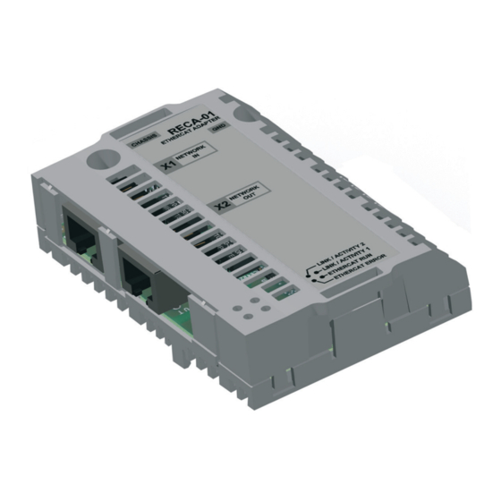
Page 83: Technical Data
Technical data What this chapter contains This chapter contains the technical specifications of the RECA-01 EtherCAT® Adapter module. RECA-01 Enclosure: 36 mm CHASSIS RECA-01 ETHERCAT ADAPTER NETWORK NETWORK LINK / ACTIVITY 2 LINK / ACTIVITY 1 ETHERCAT RUN ETHERCAT ERROR 62 mm Figure 8. -
Page 84: Ethercat® Link
Connectors: • 34-pin parallel bus connector • 2 RJ-45 connectors (X1 and X2) Current consumption: • 290 mA average (5 V), supplied by the drive control board. General: • Estimated min. lifetime: 100 000 h • All materials are UL/CSA approved. •... - Page 85 Product and service inquiries Address any inquiries about the product to your local ABB representative, quoting the type designation and serial number of the unit in question. A listing of ABB sales, support and service contacts can be found by navigating to www.abb.com/drives selecting Sales, Support and Service network.
- Page 86 ABB Oy ABB Inc. ABB Beijing Drive Systems Co. Ltd. AC Drives Automation Technologies No. 1, Block D, A-10 Jiuxianqiao Beilu P.O. Box 184 Drives & Motors Chaoyang District FI-00381 HELSINKI 16250 West Glendale Drive Beijing, P.R. China, 100015 FINLAND...