Table of Contents
Advertisement
Quick Links
Advertisement
Table of Contents

Related Manuals for ABB RDNA-01


Summary of Contents for ABB RDNA-01
- Page 1 ABB Drives User’s Manual DeviceNet Adapter Module RDNA-01...
- Page 3 DeviceNet Adapter Module RDNA-01 User’s Manual 3AFE64504223 Rev D EFFECTIVE: 16.07.2007 © 2007 ABB Oy. All Rights Reserved.
-
Page 5: Safety Instructions
Safety instructions Overview This chapter states the general safety instructions that must be followed when installing and operating the RDNA-01 DeviceNet Adapter module. The material in this chapter must be studied before attempting any work on the unit. In addition to the safety instructions given below, read the... - Page 6 Safety instructions...
-
Page 7: Table Of Contents
DeviceNet Bus topology ........15 The RDNA-01 DeviceNet Adapter module ......16 Compatibility . - Page 8 ODVA input attributes ........49 ABB Drives communication profile ....... . 51 The control word and the status word .
- Page 9 RDNA-01 status codes ........
- Page 10 Table of contents...
-
Page 11: Introduction
Overview contains short descriptions of the DeviceNet protocol and the RDNA-01 DeviceNet Adapter module, a delivery checklist and information on the manufacturer’s warranty. Quick start-up guide contains a short description of how to set up the RDNA-01 DeviceNet Adapter module using the ACS800 drive as an example. -
Page 12: Further Information
Product and service inquiries Address any inquiries about the product to your local ABB representative, quoting the type code and serial number of the unit in question. A listing of ABB sales, support and service contacts can be found by navigating to www.abb.com/drives and selecting Drives –... -
Page 13: Providing Feedback On Abb Drives Manuals
Providing feedback on ABB Drives manuals Your comments on our manuals are welcome. Go to www.abb.com/drives, then select successively Drives – Document Library – Manuals feedback form. Introduction... - Page 14 Introduction...
-
Page 15: Overview
Overview Overview This chapter contains a short description of DeviceNet bus topology, the RDNA-01 Adapter module, a delivery checklist, and warranty information. Further information can be obtained from www.odva.org. DeviceNet Bus topology The DeviceNet network has a linear bus topology. Terminating resistors are required on each end of the trunk line. -
Page 16: The Rdna-01 Devicenet Adapter Module
• read and write drive parameter values • reset a drive fault. The RDNA-01 acts as a Class 2 slave only with predefined master-slave connection set services. These include the Explicit Messaging, the Poll-Response service and the Change of State/ Cyclic service. -
Page 17: Compatibility
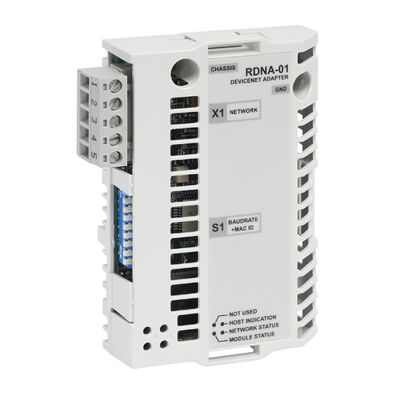
Figure 2. The construction of the DeviceNet link and the module layout of the RDNA-01 Compatibility The RDNA-01 is compatible with all scanners working according to ODVA DeviceNet specifications. Delivery check The option package for the RDNA-01 DeviceNet Adapter module contains: •... -
Page 18: Warranty And Liability Information
(12) months after installation or twenty-four (24) months from date of manufacturing, whichever first occurs. The local ABB office or distributor may grant a warranty period different to the above and refer to local terms of liability as defined in the supply contract. -
Page 19: Quick Start-Up Guide
• Select and import the EDS file for drive, for example ACS800_Standard_RDNA01_appl1.36_Typical_filerev3.2.EDS. For more help on choosing the correct file, refer to ABB EDS Selection Guide document delivered with the EDS files. Note: Only one EDS file with the same Product ID and Vendor code can be installed in the PLC at a time. - Page 20 • Add drive to network in RSNetWorx for DeviceNet. • Configure device MAC address. Quick start-up guide...
- Page 21 • Configure the DeviceNet Scanner. Add the drive to Scanlist and edit I/O parameters. Select Polled or Change of State/Cyclic. Then enter the input and output sizes of the I/O assemblies that will be used (e.g. for Basic Speed Control Assemblies 20 and 70, each size is set to 4 bytes).
- Page 22 • Download the scanner settings to the device in online mode. • Add your DeviceNet scanner to an RSLogix 5000 project. You should get new Controller Tags Local:<slot>:I and Local:<slot>:O. You can use them to access the data as mapped above: Local:<slot>:O.Data[0] is the Control Word Local:<slot>:O.Data[1] is the Reference Local:<slot>:I.Data[0] is the Status Word...
-
Page 23: Mechanical And Electrical Installation
Mechanical and electrical installation • Insert the RDNA-01 into its specified slot in the drive. • Fasten the screws. • Plug the fieldbus connector into the module. Drive configuration Note: Configuring the drive for communication with the module is dependent on the drive type. Refer to the Firmware Manual of the drive for detailed information on configuring the drive to use the communication module. -
Page 24: Example Configurations
Note: The new settings take effect only when the module is powered up the next time or when a ‘Fieldbus Adapter parameter refresh’ is given (see the drive documentation). Example Configurations ODVA Basic Speed Control on ACS800 Drive Parameter Example setting for ACS800 10.01 EXT1 STRT/STP/DIR COMM.CW 10.03 REF DIRECTION... - Page 25 ABB Drives profile on ACS800 Drive Parameter Example setting for ACS800 10.01 EXT1 STRT/STP/DIR COMM.CW 10.03 REF DIRECTION REQUEST 11.03 EXT REF1 SELECT COMM. REF 16.01 RUN ENABLE 16.04 FAULT RESET SEL COMM.CW 51.01 MODULE TYPE DEVICENET 51.02 Module MacID 51.03 Module baud rate...
- Page 26 ABB Drives profile with user specific assemblies on ACS800 Drive Parameter Example setting for ACS800 10.01 EXT1 STRT/STP/DIR COMM.CW 10.03 REF DIRECTION REQUEST 11.03 EXT REF1 SELECT COMM. REF 16.01 RUN ENABLE 16.04 FAULT RESET SEL COMM.CW 51.01 MODULE TYPE DEVICENET 51.02 Module MacID...
- Page 27 ODVA Extended Speed Control plus Drive Parameters assemblies on ACS800 Drive Parameter Example setting for ACS800 10.01 EXT1 STRT/STP/DIR COMM.CW 10.03 REF DIRECTION REQUEST 11.03 EXT REF1 SELECT COMM. REF 16.01 RUN ENABLE 16.04 FAULT RESET SEL COMM.CW 51.01 MODULE TYPE DEVICENET 51.02 Module MacID 51.03 Module baud rate...
- Page 28 Actual value 1 are fixed in instances 121 and 171 and not included to the VSA I/ O size. 98.02 COMM MODULE LINK FIELDBUS 98.07 COMM PROFILE ABB DRIVES Note: Remember to change the size of transferred data in the DeviceNet scanner settings. Quick start-up guide...
-
Page 29: Mechanical Installation
Hardware Manual. Mounting The RDNA-01 is to be inserted into its option slot inside the drive. The module is held in place with plastic retaining clips and two screws. The screws also provide the earthing of the I/O cable shield connected to the module, and interconnect the GND signals of the module and the control board of the drive. - Page 30 Mechanical installation...
-
Page 31: Electrical Installation
Avoid parallel runs. Use bushings at cable entries. DIP switch settings DIP switches on the printed circuit board of the RDNA-01 are used to select node address number and bus speed for the module. Use the table below to set the values. Note that switch 3 is the most significant bit of the node address number. - Page 32 Bit rate Binary DIP switch 125 kbit/s 1 2 3 4 5 6 7 8 250 kbit/s 1 2 3 4 5 6 7 8 500 kbit/s 1 2 3 4 5 6 7 8 Node no. Binary 000001 1 2 3 4 5 6 7 8 000010 1 2 3 4 5 6 7 8 •...
-
Page 33: Devicenet Connection
DeviceNet connection The bus cable is connected to terminal block X1 on the RDNA-01. The terminal block is described below. Description Isolated ground CAN_L CAN_L bus line SHLD Network cable shield CAN_H CAN_H bus line Isolated 24 V DC voltage supply... -
Page 34: Connection Examples
Connection examples 5-pin micro-style connector Network +24 V power supply Male micro-style connector CAN_L RDNA SHLD CAN_H 5-pin mini-style connector Network power supply +24 V Male mini-style connector CAN_L RDNA SHLD CAN_H Standard open-style screw connector +24 V Network power supply CAN_L RDNA SHLD... -
Page 35: Drive Configuration
(Normally, a parameter must be adjusted to activate the communication. See the drive documentation.) As communication between the drive and the RDNA-01 is established, several configuration parameters are copied to the drive. These parameters (shown in Table 1.) must be checked first... - Page 36 Table 1. The RDNA-01 configuration parameters Fieldbus Parameter name Alternative settings Default par. no. setting MODULE TYPE DEVICENET DEVICENET Module MacID 0 … 63 Module Baud rate 0 = 125 kBit/s; 1 = 250 kBit/s; 2 = 500 kBit/s HW/SW Option...
- Page 37 Input I/O Par 9 0 … 32767 VSA I/O Size 0 … 9 Note: The Default values are used when the module is connected to the drive for the first time. The parameters in the fieldbus group must be set up for the current application. 01 MODULE TYPE Shows the connected communication option module type.
- Page 38 04 HW/SW Option Defines the selection source of module MacID and baud rate. 0 = selection of MAC ID and baud rate via the DIP switches enabled. 1 = selection of MAC ID and baud rate via parameters 02 and 03 and via the DeviceNet Object enabled (see section DeviceNet Object, Class 0x03...
- Page 39 Status word and Actual value 1 are fixed but it is possible to increase the number of inputs and outputs. The instances 100, 101, 102 and 103 are so-called ABB Drives instances as defined by ABB, i.e. the control word, status word, speed reference and speed actual value are defined by the ABB Drives communication profile.
- Page 40 Note: The output instances carry data from the master to the drive and the input instances from the drive to the master. Drive configuration...
- Page 41 Generic Drive profile Generic Drive profile Generic Drive profile Generic Drive profile Generic Drive profile ABB Drives profile ABB Drives profile ABB Drives profile ABB Drives profile Note: Using instance 103 in Generic drive profile with ODVA output instances (20, 21, 121) is allowed but not recommended.
- Page 42 08 Output I/O Par 1 Defines the data word or drive parameter that can be written with Assembly object instances 102 and 121 (see sections User Specific assembly EXTENDED SPEED CONTROL PLUS DRIVE PARAMETERS assembly in chapter Communication The content is defined by a decimal number in the range of 0 to 32767 as follows: not used 1 - 99...
- Page 43 09 to 11 Output I/O Par 2 to Output I/O Par 4 See parameter 08 Output I/O Par 12 Input I/O Par 1 Defines a data word or drive parameter that can be read with Assembly object instances 103 and 171 (see sections User Specific assembly EXTENDED SPEED CONTROL PLUS...
- Page 44 13 to 15 Input I/O Par 2 to Input I/O Par 4 See parameter 12 Input I/O Par 16 to 20 Output I/O Par 5 to Output I/O Par 9 See parameter 08 Output I/O Par 21 to 25 Input I/O Par 5 to Input I/O Par 9 See parameter 12 Input I/O Par 26 VSA I/O Size...
-
Page 45: Master Configuration
Note: Only one EDS file with the same DeviceNet Product Code can be installed in the PLC at a time. To enable the use of different ABB drive types on the same DeviceNet network, a unique Product Code has been given to each drive type and application combination. - Page 46 The extended EDS files are intended for applications where access to the drive parameters via the DeviceNet network is required. The extended EDS files for ABB drives are specific to each drive type and application program revision. In addition, most extended EDS files need to be modified by hand to suit the application.
-
Page 47: Communication Profiles
With the RDNA-01 module, the DeviceNet network may employ either the ODVA AC/DC drive profile or the ABB Drives profile. The ODVA AC/DC drive profile This section briefly describes the ODVA AC/DC Drive profiles. -
Page 48: Odva Output Attributes
DeviceNet Master to set or get predefined groups of attributes in a single message exchange. Assembly Instances supported by the RDNA-01 are listed and defined in chapter Communication, page ODVA output attributes This section briefly describes the instances found in the ODVA AC/DC Drive Profiles output assemblies. -
Page 49: Odva Input Attributes
Net Ctrl (Control Supervisor Object) This attribute requests that the drive Run/Stop command be supplied locally (Net Ctrl = 0) or by the network (Net Ctrl = 1). Net Ref (AC/DC Drive Object) This attribute requests that the drive speed and torque references be supplied locally (Net Ref = 0) or by the network (Net Ref = 1). - Page 50 Ready (Control Supervisor Object) This attribute indicates that the Control Supervisor Object state machine (see State (Control Supervisor Object) below) is in the Ready, Running or Stopping state. Ctrl From Net (Control Supervisor Object) This attribute indicates if the Run/Stop command is being supplied locally (Ctrl From Net = 0) or by the network (Ctrl From Net = 1).
-
Page 51: Abb Drives Communication Profile
This attribute indicates the actual torque at which the drive is operating. The units are scaled by the Torque Scale attribute of the AC/DC Drive Object. ABB Drives communication profile The control word and the status word The Control Word is the principal means for controlling the drive from a fieldbus system. - Page 52 Communication profiles...
-
Page 53: Communication
DeviceNet specifies the wiring, and the data transfer through CAN. The RDNA-01 is a device acting as a Group 2 Server realising the Predefined Master Slave Connection Set functionality. The Off-line Connection Set functionality and UCMM are not supported. - Page 54 CONTROL or the EXTENDED SPEED CONTROL PLUS DRIVE PARAMETERS assembly is used, it must be ensured that the fieldbus is selected as the drive control source and fieldbus specific (Generic Drive profile) Control/Status Word format is selected instead of ABB Drives profile. Communication...
- Page 55 CONTROL or the EXTENDED SPEED CONTROL PLUS DRIVE PARAMETERS assembly is used, it must be ensured that the fieldbus is selected as the drive control source and fieldbus specific (Generic Drive profile) Control/Status Word format is selected instead of ABB Drives profile. Communication...
- Page 56 EXTENDED SPEED CONTROL PLUS DRIVE PARAMETERS assembly The format of the output assembly is: Instance 121 Byte Bit 7 Bit 6 Bit 5 Bit 4 Bit 3 Bit 2 Bit 1 Bit 0 NetRef NetCtrl Fault Reset Reverse Forward Speed Reference (Low Byte) Speed Reference (High Byte) Output I/O 1 (Low Byte) Output I/O 1 (High Byte)
- Page 57 The format of the input assembly is: Instance 171 Byte Bit 7 Bit 6 Bit 5 Bit 4 Bit 3 Bit 2 Bit 1 Bit 0 Ctrl Ready Running Running Warn- Faulted Refer- From From Reverse Forward ence Drive State (see section State (Control Supervisor Object) on page 50) Speed Actual (Low Byte)
- Page 58 For example, if 16.04 FAULT RESET SEL is COMM, the bit is always fixed to 1. ABB Drives assembly ABB Drives assembly allows the use of the ABB Drives communication profile. The format of the output assembly is: Instance 100...
- Page 59 User Specific assembly User Specific assembly allows the use of the ABB Drives communication profile. The format of the output assembly is: Instance 102 Byte Bit 7 Bit 6 Bit 5 Bit 4 Bit 3 Bit 2 Bit 1 Bit 0...
- Page 60 The format of the input assembly is: Instance 103 Byte Bit 7 Bit 6 Bit 5 Bit 4 Bit 3 Bit 2 Bit 1 Bit 0 Input I/O 1 (Low Byte) Input I/O 1 (High Byte) Input I/O 2 (Low Byte) Input I/O 2 (High Byte) Input I/O 3 (Low Byte) Input I/O 3 (High Byte)
-
Page 61: Drive Parameter Handling
Drive parameter handling With the RDNA-01, drive parameters can also be accessed. The function is implemented by employing the so-called Explicit Messaging properties of the DeviceNet protocol. Explicit Messaging makes use of objects consisting of three parts, Class, Instance, and Attribute. - Page 62 Attribute explanations Vendor ID Vendor IDs are managed by the Open DeviceNet Vendor Association, Inc. (ODVA). The ABB Vendor ID is 46. Device Type The list of device types is managed by ODVA. It is used to identify the device profile that a particular product is using.
- Page 63 Product Code Every ABB drive type or application of the drive has a dedicated product code. Revision Revision attribute, which consists of Major and Minor Revisions, identifies the Revision of the item the Identity Object is representing. Status This attribute represents the current status of the entire device. Its value changes as the state of the device changes.
-
Page 64: Devicenet Object, Class 0X03
Bit(s) Type/Name Definition Major TRUE indicates the device detected a problem Unrecoverable Fault which caused the device to go into the “Major Unrecoverable Fault” state. 12,13,14, Reserved, set to 0. Serial Number: This attribute is a number used in conjunction with the Vendor ID to form a unique identifier for each device on DeviceNet. - Page 65 Instance Attributes # Attribute Services Description Default, Data type name Minimum, Maximum 1 MAC ID Get_Attribute_Single Node address -,0,63 UINT8 2 Baud Rate Get_Attribute_Single The baud rate of the -,0,2 UINT8 device 5 Allocation Get_Attribute_Single Allocation Choice N/A,N/A, Struct information Master’s Mac ID UINT8 UINT8...
-
Page 66: Configuration Object, Class 0X91
UINT8 6 Input_Assy_Inst Get, Set Input assembly instance UINT8 7 Idle mode Get, Set Action taken when the master UINT8 goes to idle state when using the ABB communication profile. 0 = fault 1 = freeze data (keep running) Communication... -
Page 67: Devicenet Connection Object, Class 0X05
DeviceNet Connection Object, Class 0x05 The Connection Class allocates and manages the internal resources associated with both I/O and Explicit Messaging Connections. The specific instance generated by the Connection Class is referred to as Connection Instance or Connection Object. Instance numbering Explicit messaging connection Polled connection or cos/cyclic consuming connection Cos/cyclic producing connection... - Page 68 # Attribute Services Description Default, Data name Minimum, type Maximum 6 Comm Defines the Message Group(s) N/A,N/A, UINT8 Characteristics across which productions and consumptions are associated in this Connection. 7 Produced Maximum number of bytes 512,512, UINT16 Connection transmitted across this Size Connection 8 Consumed...
- Page 69 Polled I/O Connection Instance (Instance 2) # Attribute Services Description Default, Data name Minimum, type Maximum 1 State State of the object 1,0,4 UINT8 2 Instance Type Get Indicates either IO or messaging 0,0,1 UINT8 connection. 3 Transport Defines the behaviour of the 0x83, UINT8 Class Trigger...
- Page 70 # Attribute Services Description Default, Data name Minimum, type Maximum 14 Produced Application Object producing 0x62 Array of Connection data on this Connection 0x39 UINT8 Path 0x37, N/A,N/A 15 Consumed Number of bytes in the 3,3,3 UINT16 Connection consumed_connection_path Path Length length attribute 16 Consumed Specifies the Application...
-
Page 71: Acknowledge Handler Object, Class 0X2B
# Attribute Services Description Default, Data name Minimum, type Maximum 7 Produced Maximum number of bytes 0,0,N/A UINT16 Connection transmitted across this Size Connection 8 Consumed Maximum number of bytes 0,0,N/A UINT16 Connection received across this Connection size 9 Expected Get,Set Defines timing associated with 0,0,0xffff... -
Page 72: Motor Data Object, Class 0X28
Class Attributes # Attribute Services Description Data type name 1 Revision Revision of the DeviceNet Object Class Array of Definition upon which the implementation is UINT8 based Instance Attributes # Attribute Services Description Default, Data name Minimum, type Maximum 1 Acknowledge Get, Set Time in milliseconds to wait for 16,1, UINT16... - Page 73 Class Attributes # Attribute Services Description Data name type 1 Revision Get Revision of the DeviceNet Object Class Defini- Array of tion upon which the implementation is based UINT8 Instance Attributes # Attribute Services Description Motor Data name type type 6 Rated Current Get, Set Rated Stator Current from motor AC/DC UINT16...
-
Page 74: Control Supervisor Object, Class 0X29
Control Supervisor Object, Class 0x29 The object models all the management functions for devices within the ‘Hierarchy of Motor Control Devices’. The behaviour of motor control devices is described by the State transition diagram and the Run/Stop event matrix. See Table 2. - Page 75 Instance Attributes # Attribute Services Description Data name type 3 Run 1 Get, Set 0 = Stop, 1 = Run BOOL 4 Run 2 Get, Set 0 = Stop, 1 = Run BOOL 5 Net Control Get, Set 0 = Local Control, 1 = Network Control BOOL 6 State 1 = Start/up, 2 = Not_ready, 3 = Ready,...
-
Page 76: Ac/Dc-Drive Object, Class 0X2A
AC/DC-Drive Object, Class 0x2A This object models the functions specific to an AC or DC Drive. Class Attributes # Attribute Services Description Data type name 1 Revision Get Revision of the DeviceNet Object Class Array of Definition upon which the implementation is UINT8 based Instance Attributes... -
Page 77: Diagnostics
Diagnostics RDNA-01 status codes The status of the DeviceNet module is indicated by a ‘fieldbus status’ parameter in the drive application program (refer to the drive documentation). IDLE The drive could not initiate communication with the DeviceNet Module. EXECUT. INIT The module is initialising and performing self-test. -
Page 78: Led Indications
LED indications The RDNA-01 module is equipped with three diagnostic LEDs. The description of the LEDs is below. Not used Host Indication Module status Network status Name Colour Function Green Steady - Device operational Steady - Unrecoverable fault Flashing - Minor fault... -
Page 79: Installation Problems
X1:1 and X1:5. • Check that the RDNA-01 module is properly inserted into the option slot. • Check the fastening of the RDNA-01 module with the 2 screws. Drive setup The fieldbus parameter group is not shown on the panel: •... - Page 80 Diagnostics...
-
Page 81: Definitions And Abbreviations
EDS file. Input In the ODVA DeviceNet specification the word ‘input’ is used to describe data flow from a device (such as the RDNA-01) to the network. I/O Assembly selection Smart networked devices (like the RDNA-01) can produce and/or consume more than one I/O value. - Page 82 RDNA-01 module. Poll Message Most DeviceNet Scanners as well as the RDNA-01 support two different data services. These are Poll and Change of State/Cyclic messages. The Poll Command is an I/O Message that is transmitted by the Master.
- Page 83 Scanlist The DeviceNet Scanner communicates with the DeviceNet Slaves in a user-defined order. This order of communication is the scanlist. The scanlist contains a complete list of the Slave nodes and the order in which the Slaves are accessed. Definitions and abbreviations...
- Page 84 Definitions and abbreviations...
-
Page 85: Technical Data
Technical data RDNA-01 Enclosure: 34 mm 62 mm Mounting: Into an option slot inside the drive Degree of protection: IP 20 Ambient conditions: The applicable ambient conditions specified for the drive in its Hardware Manual are in effect. Settings: • Through drive parameters •... -
Page 86: Fieldbus Link
Current consumption: • 250 mA max. (5 V), supplied by the RMIO board • 15 mA max. (24 V) from the network supply. General: • Estimated min. lifetime: 100 000 h • All materials are UL/CSA approved • Complies with EMC Standards EN 50081-2 and EN 50082-2 Fieldbus link Compatible Devices: Any ODVA-compliant DeviceNet scanner supporting Poll - Response commands to Group 2 only Slaves... - Page 88 ABB Oy ABB Inc. ABB Beijing Drive Systems AC Drives Automation Technologies Co. Ltd. P.O. Box 184 Drives & Motors No. 1, Block D, A-10 Jiuxianqiao FI-00381 HELSINKI 16250 West Glendale Drive Beilu FINLAND New Berlin, WI 53151 Chaoyang District Telephone +358 10 22 11 Beijing, P.R.