
Related Manuals for ABB REPL-01


Summary of Contents for ABB REPL-01
- Page 1 ABB Drives User’s Manual Ethernet POWERLINK Adapter Module REPL-01 Phone: 800.894.0412 - Fax: 888.723.4773 - Web: www.clrwtr.com - Email: info@clrwtr.com...
- Page 2 Phone: 800.894.0412 - Fax: 888.723.4773 - Web: www.clrwtr.com - Email: info@clrwtr.com...
- Page 3 Ethernet POWERLINK Adapter Module REPL-01 User’s Manual 3AUA0000052289 REV A EN EFFECTIVE: 20.03.2009 © 2009 ABB Oy. All Rights Reserved. Phone: 800.894.0412 - Fax: 888.723.4773 - Web: www.clrwtr.com - Email: info@clrwtr.com...
- Page 4 Phone: 800.894.0412 - Fax: 888.723.4773 - Web: www.clrwtr.com - Email: info@clrwtr.com...
- Page 5 Safety instructions What this chapter contains This chapter states the general safety instructions that must be followed when installing and operating the REPL-01 Ethernet POWERLINK Adapter module. The material in this chapter must be studied before attempting any work on the unit.
- Page 6 Safety instructions Phone: 800.894.0412 - Fax: 888.723.4773 - Web: www.clrwtr.com - Email: info@clrwtr.com...
-
Page 7: Table Of Contents
Product training ..........8 Providing feedback on ABB Drives manuals ......8 Overview . - Page 8 REPL-01 configuration ........
- Page 9 Actual value of the DSP 402 profile ....... 33 ABB Drives communication profile ....... . 33 The Control Word and the Status Word .
- Page 10 REPL-01 ........
-
Page 11: Safety Instructions
What this manual contains This manual contains information on the wiring, configuration and the use of the REPL-01 Ethernet POWERLINK Adapter module. It is assumed that the drive is installed and ready to operate before starting the installation of the adapter module. For more information on the installation and start-up procedures of the drive, see the appropriate drive manuals. - Page 12 Overview contains a short description of the Ethernet POWERLINK protocol and the REPL-01 Ethernet POWERLINK Adapter module, a delivery checklist, and information on the manufacturer’s warranty. Quick start-up guide contains a short description of how to set up the REPL-01 Ethernet POWERLINK Adapter module.
-
Page 13: Terms Used In This Manual
REPL-01 Ethernet Powerlink Adapter module The REPL-01 Ethernet Powerlink Adapter module is one of the optional fieldbus adapter modules available for ABB drives. The REPL-01 is a device through which an ABB drive is connected to an Ethernet POWERLINK network. Parameter A parameter is an operating instruction for the drive. -
Page 14: Product And Service Inquiries
Address any inquiries about the product to your local ABB representative, quoting the type code and serial number of the unit in question. A listing of ABB sales, support and service contacts can be found by navigating to ABB website and selecting Sales, Support and Service network. -
Page 15: Overview
Managing Node (MN). All other nodes are Controlled Nodes (CN). The REPL-01 is capable of participating in an Ethernet POWERLINK network as a CN. Unlike standard Ethernet, SCNM ensures that only one node is accessing the network at a time. -
Page 16: Repl-01 Ethernet Powerlink Adapter Module
REPL-01 Ethernet POWERLINK Adapter module The REPL-01 Ethernet POWERLINK Adapter module is an optional device for ABB drives which enables the connection of the drive to an Ethernet POWERLINK network. Through the REPL-01 Ethernet POWERLINK Adapter module it is possible to •... -
Page 17: Compatibility
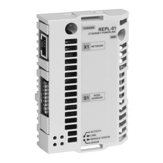
ERROR Top view Side view Figure 1. The REPL-01 Adapter module. Compatibility The REPL-01 module is compatible with all master stations that support the Ethernet POWERLINK protocol. Delivery check The option package for the REPL-01 Ethernet POWERLINK Adapter module contains: •... - Page 18 The local ABB office or distributor may grant a warranty period different to the above and refer to local terms of liability as defined in the supply contract. The manufacturer is not responsible for •...
-
Page 19: Quick Start-Up Guide
7 and 8 to ON position and the actuators 1…6 to OFF position. 2. Mount the REPL-01. • Insert the REPL-01 into its specified slot in the drive (SLOT2 for ACS550, SLOT1 for ACS800). • Fasten the two screws. -
Page 20: Drive Configuration
2. Enable the fieldbus module by setting parameter 98.02 COMM MODULE LINK to FIELDBUS. 3. ACS800 only: Set the drive to use the ABB Drives profile by setting parameter 98.07 COMM PROFILE to ABB DRIVES. 4. Set parameter 51.02 to 1 (Transparent mode). -
Page 21: Plc Configuration
This section describes the steps to configure the PLC with B&R Automation Studio PC software, so that it can be used to control the drive using the REPL-01 module. 1. Create a new project in Automation Studio for your PLC, or open an existing project. -
Page 22: Adding The .Xdd File
Open. Associating the REPL-01 with the PLC When the .xdd file has been imported, add the REPL-01 module to the list of POWERLINK devices associated with the PLC. 1. In the Project Explorer window, right-click the CPU node, and click Open POWERLINK in the pop-up menu. -
Page 23: Mapping Objects Required For Controlling The Drive
Mapping objects required for controlling the drive 1. In the Project Explorer window, right-click the entry for the REPL-01 module, and select Open I/O Configuration in the pop- up menu. 2. In the I/O Configuration window, make the following settings: •... -
Page 24: Building A Project And Transfering It To The Plc
1. To open the I/O Mapping window, right-click the REPL-01 module entry in the Project Explorer window, and then click Open I/O Mapping in the pop-up menu. -
Page 25: Mechanical Installation
Mounting The REPL-01 module is to be inserted into its specific position in the drive. The module is held in place with plastic retaining clips and two screws. The screws also provide the earthing of the... - Page 26 Mechanical installation Phone: 800.894.0412 - Fax: 888.723.4773 - Web: www.clrwtr.com - Email: info@clrwtr.com...
-
Page 27: Electrical Installation
Ethernet POWERLINK connections The network cable can be connected to the RJ45 connector (X1) on the REPL-01 module. Standard CAT 5 UTP, CAT 5 FTP or CAT 5 STP cables can be used. If CAT 5 STP is used, the cable shield is internally connected to the drive frame through the module. -
Page 28: Ethernet Powerlink Network Topology
The use of repeating hubs instead of switches is recommended in an Ethernet POWERLINK network to minimize delay and jitter. Use class 2 hubs. REPL-01 does not have an internal hub and thus, an external hub is required. REPL-01 supports 100 Mbit/s Ethernet POWERLINK. Slave... -
Page 29: Drive Configuration
ABB drives can receive control information from multiple sources including digital inputs, analogue inputs, the drive control panel and a communication module (e.g. REPL-01). ABB drives allow the user to separately determine the source for each type of control information (Start, Stop, Direction, Reference, Fault Reset, etc.). -
Page 30: The Repl-01 Configuration Parameters
If this parameter is undefined, the communication between the drive and the module has not been established. 2 TRANSPARENT/PROFILE MODE This parameter is used for choosing either the transparent (ABB Drives) or the DSP 402 communication profile. This selection can also be changed with object 0×2004 (hex). -
Page 31: Master Configuration
POWERLINK master to communicate with the REPL-01 Ethernet POWERLINK Adapter module. Configuring the system After the REPL-01 has been mechanically and electrically installed according to the instructions in previous chapters and initialized by the drive, the master system must be prepared for communication with the module. - Page 32 Master configuration Phone: 800.894.0412 - Fax: 888.723.4773 - Web: www.clrwtr.com - Email: info@clrwtr.com...
-
Page 33: Communication Profiles
(Control Word, Status Word, references and actual values) between the master station and the drive. With the REPL-01 module, either the CANopen DSP 402 (Device Profile Drives and Motion Control) profile or the ABB Drives profile may be employed. The Control Word, Status Word, references and actual values of these profiles are described in the following sections. -
Page 34: Supported Mode Of Operation
The DSP 402 profile offers a choice of several modes of operation. These modes define the operation of the drive. The REPL-01 supports the Velocity mode, which is a basic operation mode used to control the velocity of the drive. - Page 35 Name Value Description Ramp function Ramp function generator input value is set generator use ref. to zero. Normal operation: Ramp function generator input is the ramp reference. Fault reset The functionality of bits 0…3 and 7 are described in table Operation of bits 0…3 and 7 of the DSP 402 Control Word.
- Page 36 ** When Control Word bit 3 (Enable operation) is 1, the drive does not stay in the SWITCHED ON state, but immediately transitions to state OPERATION ENABLED. Status Word of DSP 402 Name Value Description Ready to switch ON Not ready to switch ON Ready to switch ON Switched ON Not switched ON...
- Page 37 Name Value Description 12…13 Reserved Drive specific ACx550: External control location EXT1 selected ACx550: External control location EXT2 selected ACS800: User settable* Drive specific ACx550: Not used ACS800: User settable* * The functionality of the vendor-specific bits in ACS800 can vary according to the control program.
- Page 38 from any state CW: Control Word FAULT REACTION START SW: Status Word ACTIVE SW: xxxxxxxxx0xx1111 Power-on, Fault reaction State transition self-initialisation completed NOT READY FAULT TO SWITCH ON SW: xxxxxxxxx0xx0000 SW: xxxxxxxxx0xx1000 Initialised CW: xxxxxxxx1xxxxxxx (15) successfully SWITCH-ON DISABLED SW: xxxxxxxxx1xx0000 CW: xxxxxxxx0xxxx110 CW: xxxxxxxx0xxxx01x CW: xxxxxxxx0xxxxx0x...
-
Page 39: Reference Of The Dsp 402 Profile
Vl dimension factor object (object 0x604C hex): Drive actual speed = Control effort × Vl dimension factor The scaling is 1 by default. ABB Drives communication profile The Control Word and the Status Word The Control Word is the principal means for controlling the drive from a fieldbus system. -
Page 40: Control Word And Status Word Of The Abb Drives Profile
State machine, ABB Drives communication profile page 38). The ABB Drives profile Control Word can be found in object 0x2005 (hex) (Transparent Control Word) and the Status Word in object 0x2007 (hex) (Transparent Status Word). Control Word and Status Word of the ABB Drives profile The following table presents the Control Word of the ABB Drives communication profile. - Page 41 Control Word of ABB Drives profile Name Value STATE/Description INHIBIT_ Proceed to OPERATION ENABLED. OPERATION Note: Run enable signal must be active; see the drive manuals. If the drive is set to receive the Run enable signal from the fieldbus, this bit activates the signal.
- Page 42 12 to Reserved The following table presents the Status Word of the ABB Drives communication profile. The upper case boldface text refers to the states shown in figure State machine, ABB Drives communication...
- Page 43 Status Word of the ABB Drives profile Name Value STATE/Description OFF_2_STA OFF2 inactive OFF2 ACTIVE OFF_3_STA OFF3 inactive OFF3 ACTIVE SWC_ON_ SWITCH-ON INHIBITED INHIB – ALARM Warning/Alarm No warning/alarm OPERATING. Actual value equals reference = is SETPOINT within tolerance limits, i.e. in speed control, speed error is 10% max.
- Page 44 (CW=xxxx x1xx xx11 1111) RFG: ACCELERATOR state ENABLED condition (CW=xxxx x1xx x111 1111) rising edge OPERATION the bit (SW Bit8=1) Figure 5. State machine, ABB Drives communication profile Communication profiles Phone: 800.894.0412 - Fax: 888.723.4773 - Web: www.clrwtr.com - Email: info@clrwtr.com...
-
Page 45: References
ABB drives can receive control information from multiple sources including analogue and digital inputs, the drive control panel and a communication module (e.g. REPL-01). In order to have the drive controlled through the fieldbus, the module must be defined as the source for control information, e.g. -
Page 46: Actual Values
Negative actual values are formed by calculating the two’s complement from the corresponding positive actual values. The ABB Drives profile actual values can be found in objects 0x2008 (hex) (Transparent Actual Value) and 0x4000 (hex), subindex 6 (Actual Value 2). -
Page 47: Communication
Communication What this chapter contains This chapter describes the communication on an Ethernet POWERLINK network. Ethernet POWERLINK communication cycle In an Ethernet POWERLINK network, one of the nodes, for example a PLC, motion controller or industrial PC, is designated to function as the Managing Node (MN), the master in the network. -
Page 48: Ethernet Powerlink State Machine
In the NMT_GS_RESET_CONFIGURATION sub-state, the node address of the device is identified and it is determined whether it is configured as a MN or CN. The REPL-01 is a CN and thus, it enters the NMT CN state machine in the NMT_GS_COMMUNICATING super-state. -
Page 49: Nmt_Gs_Communicating
NMT_GS_COMMUNICATING NMT_CS_NOT_ACTIVE This is a non-permanent state that allows a starting node to recognize the current network state. Timeout for SoC, PReq, PRes and SoA frames trigger the device to enter state NTM_CS_BASIC_ETHERNET. The NMT_CS_PREOPERATIONAL states NMT_CS_PREOPERATIONAL_1 is one of the sub-states in the superstate NMT_CS_EPL_MODE. - Page 50 NMT_GS_INITIALISATION NMT_CS NMT CN State Machine NMT_CS_NOT_ACTIVE NMT_CS_BASIC_ETHERNET SoA, SoC NMT_CS_EPL_MODE Error Condition NMT_CS_PREOPERATIONAL_1 NMT_CS_PREOPERATIONAL_2 NMT_CS_READY_TO_OPERATE NMT StartNode NMT_CS_OPERATIONAL NMT_CS_STOPPED NMT StopNode Communication Phone: 800.894.0412 - Fax: 888.723.4773 - Web: www.clrwtr.com - Email: info@clrwtr.com...
-
Page 51: Ds 301 And Ds 402 Specification
Words, References and Actual Values, but most dictionary objects and drive parameters can be mapped for cyclical communication. The REPL-01 has one receive PDO (Rx PDO) and one transmit PDO (Tx PDO). In each PDO, 0…16 application objects can be mapped. -
Page 52: Service Data Objects (Sdos)
With SDO communication, all CANopen objects in the REPL-01 can be accessed. Ethernet POWERLINK provides different kinds of SDO transfer methods. REPL-01 supports SDO transfer via Ethernet POWERLNIK ASnd frames in asynchronous phase. For further information, see Ethernet POWERLINK Communication Profile Specification Version 1.1.0. -
Page 53: Network Management Services
When the Read by Index command is used, the client of an SDO (the MN) requests the REPL-01 to upload data to the client. To address the objects, Indexes and Sub-Indexes are used. An Index (0…65535) specifies and entry of the device object and a Sub-Index (0…254) specifies a component of the device object... -
Page 54: Error Entry Specification
Via NMT State Response service, the CNs signal their states to the MN. IdentResponse Service is used by the MN to identify configured but unrecognized CNs at system start-up or after loss of communication. See Appendix: IdentResponse Frame for more information. -
Page 55: Diagnostics
Diagnostics LED indications The REPL-01 module is equipped with four diagnostic LEDs. The description of the LEDs is presented below. ACTIVITY LINK ERROR MODULE STATUS Name Function Off: No link Green: Module is connected to Ethernet The green MODULE STATUS LED indicates the status of the Ethernet POWERLINK network state machine. - Page 56 ACTIVITY LINK ERROR MODULE STATUS The red ERROR LED indicates the presence of any errors. Off: Normal operation On: An error has occured. Off: No traffic Flickering: (On 50 ms, off 50 ms) There is traffic on Ethernet Diagnostics Phone: 800.894.0412 - Fax: 888.723.4773 - Web: www.clrwtr.com - Email: info@clrwtr.com...
-
Page 57: Canopen Object Dictionary
Overview The CANopen Object Dictionary contains all the configuration data of the REPL-01 module. The objects in the dictionary can be accessed with SDO services, and many of the dictionary objects can be mapped for cyclic communication in PDOs. Each object is addressed using a 16-bit index. - Page 58 0×1006 Communication cycle time interval 0×1008 Manufacturer Visible Device name. The constant string is device name string REPL-01 and ACxxxx. 0×1009 Manufacturer Visible The hardware version of the hardware string module. version 0×100A Manufacturer Visible The software version.
- Page 59 Index Sub- Attri- Name Type Information (hex) index bute 0×1010 Store Largest supported subindex. parameters If the value of bit 0 of the subindexes is 1, the device saves parameters on command. Parameters can be saved by writing 0x65766173 ("evas") to the relevant subindex.
- Page 60 Restore drive Restore drive default parameters. parameters 0×1018 Identity object Number of entries Vendor ID Value: 0×B7 = ABB (Oy) Product code Drive dependent, e.g. 0×201 = ACS550 Revision Module software revision. Format: 0×XXXX.YYYY Serial number Serial number of the module.
- Page 61 RW* Used by the MN to verify if the time module is properly configured. 0×1030 Interface Group Number of entries. Always 9. Interface Index Interface Visible ABB REPL-01 HW 1.0 Description string Interface Type 6 (Ethernet CSMA/CD) Interface Mtu Interface Phys Octet MAC address assigned during...
- Page 62 Index Sub- Attri- Name Type Information (hex) index bute 0×1600 Receive PDO Number of mapped application Mapping objects (0…32). See also the note Process Data Objects (PDO) information on drive support. Mapped object Mapped object 0×1800 Transmit PDO Number of entries. Always 2. Communication Node ID Mapping...
- Page 63 Index Sub- Attri- Name Type Information (hex) index bute Cumulative count Threshold count U32 Threshold 0×1C0F CRC errors Number of entries. Always 3. Cumulative count Threshold count U32 Threshold 0×1C14 Loss of frame tolerance 0×1F82 Feature flags Always 0x45. 0×1F83 EPL version Always 0x20.
-
Page 64: Manufacturer Specific Profile Objects
* The value written to this object is valid after reset. Manufacturer specific profile objects The manufacturer specific profile object contains the ABB Drives profile Control and Status Words, Reference and Actual Value. In addition, objects for diagnostic data and PID configuration are included. -
Page 65: Manufacturer Specific Profile Objects
0×2004 Transparent / RW An object for choosing the Profile mode communication profile 0 = Profile mode (DSP 402) 1 = Transparent (ABB Drives) profile mode This object can only be modified in the state PRE-OP2. 0×2005 Transparent RW See chapter... -
Page 66: Drive Data Sets
Index Sub- Attri- Name Type Information (hex) index bute 0×200B Vendor specific Number of entries fault codes See the drive manual for descriptions of the fault codes. Fault code 1 (latest) Fault code 2 Fault code 3 Fault code 4 Fault code 5 Drive data sets With the object 0x4000 (hex) the data set area of the drive can be... -
Page 67: Drive Data Sets
Drive data sets Index Sub- Attri- Name Type Information (hex) index bute 0×4000 Number of entries Number of supported data sets depends on the application software of the drive. Control Word Data set 1 Word 1 Reference 1 INT16 Data set 1 Word 2 Reference 2 INT16 Data set 1 Word 3... -
Page 68: Drive Signals And Parameters
use the same parameter mapping system. The Object Dictionary Index equals drive parameter group in hexadecimal format + 4000 (hex) and the subindex is parameter index. For example, the index for the drive parameter 30.19 equals 1E (hex) + 4000 (hex) = 401E (hex) and the subindex = 19 (dec) = 13 (hex). -
Page 69: Dsp 402 Profile Objects
Index (hex) Subindex Name Type Attribute Information Subindex 0 = number of mapped objects. U16, INT16, U32 or INT32 Depends on parameter type of the drive. See the appropriate drive firmware manual. DSP 402 profile objects The DSP 402 profile objects describe objects for monitoring and controlling frequency controllers. - Page 70 Index Sub- Attri- Name Type Information (hex) index bute 0×6048 VI velocity INT8 Number of entries acceleration Slope of the acceleration ramp = delta speed / delta time. Delta speed Delta time 0×6049 VI velocity INT8 Number of entries deceleration Slope of the deceleration ramp = delta speed / delta time.
- Page 71 Index Sub- Attri- Name Type Information (hex) index bute 0×6061 Modes of INT8 A read only copy of object 0×6060 operation display 0×6078 Current actual INT16 RO The actual output current value CANopen object dictionary Phone: 800.894.0412 - Fax: 888.723.4773 - Web: www.clrwtr.com - Email: info@clrwtr.com...
- Page 72 CANopen object dictionary Phone: 800.894.0412 - Fax: 888.723.4773 - Web: www.clrwtr.com - Email: info@clrwtr.com...
-
Page 73: Emergency Messages, Ds301 And Ds402
Emergency messages, DS301 and DS402 What this chapter contains This chapter contains a list of the CANopen error codes. Error codes Error codes can be read from the objects 0×200B and 0×603F (hex). Additionally, the MN can query the status of the CN with the StatusResponse service. - Page 74 Error Meaning code (hex) 2211 Internal current No. 1 2212 Internal current No. 2 2213 Overcurrent in ramp function 2214 Overcurrent in the sequence 2220 Continuous overcurrent 2221 Continuous overcurrent No. 1 2222 Continuous overcurrent No. 2 2230 Short circuit / earth leakage 2240 Earth leakage 2250...
- Page 75 Error Meaning code (hex) 3122 Mains undervoltage phase L2 3123 Mains undervoltage phase L3 3130 Phase failure 3131 Phase failure L1 3132 Phase failure L2 3133 Phase failure L3 3134 Phase sequence 3140 Mains frequency 3141 Mains frequency too great 3142 Mains frequency too small 3200...
- Page 76 Error Meaning code (hex) 4130 Temperature supply air 4140 Temperature air outlet 4200 Temperature device 4210 Excess temperature device 4220 Too low temperature device 4300 Temperature drive 4310 Excess temperature drive 4320 Too low temperature drive 4400 Temperature supply 4410 Excess temperature supply 4420 Too low temperature supply...
- Page 77 Error Meaning code (hex) 5430 Input stages 5440 Contactors 5441 Contactor 1 = manufacturer specific 5442 Contactor 2 = manufacturer specific 5443 Contactor 3 = manufacturer specific 5444 Contactor 4 = manufacturer specific 5445 Contactor 5 = manufacturer specific 5450 Fuses 5451 S1 = L1...
- Page 78 Error Meaning code (hex) 6330 Ethernet POWERLINK module configuration error 7000 Additional modules 7100 Power 7110 Brake chopper 7111 Failure brake chopper 7112 Overcurrent brake chopper 7113 Protective circuit brake chopper 7120 Motor 7121 Motor blocked 7122 Motor error or communication malfunc. 7123 Motor tilted 7200...
- Page 79 Error Meaning code (hex) 8312 Difficult start up 8313 Standstill torque 8321 Insufficient torque 8331 Torque fault 8400 Rotational speed controller 8500 Position controller 8600 Positioning controller 8611 Following error 8612 Reference limit 8700 Sync controller 8800 Winding controller 9000 External error F000 Additional functions...
- Page 80 Emergency messages, DS301 and DS402 Phone: 800.894.0412 - Fax: 888.723.4773 - Web: www.clrwtr.com - Email: info@clrwtr.com...
-
Page 81: Definitions And Abbreviations
Definitions and abbreviations Controlled Node; A node in a POWERLINK network without the ability to manage the SCNM mechanism. Device Description File All device-specific information is stored in the Device Description File (XDD) of each device. Managing Node; A node capable of managing the SCNM mechanism in a POWERLINK network. - Page 82 Denotes read/write access. Service Data Object; Used for transmitting non time critical data, such as parameters. SCNM Slot Communication Network Management; In a POWERLINK network, the MN allocates data transfer time for data from each node in a cyclic manner within a guaranteed cycle time. Within each cycle there are slots for Isochronous Data, and for Asynchronous Data for ad-hoc communication.
-
Page 83: Technical Data
Technical data What this chapter contains This chapter contains the technical specifications of the REPL-01 Ethernet POWERLINK Adapter module. REPL-01 Enclosure: 36 mm CHASSIS REPL-01 ETHERNET POWERLINK NETWORK NODE ADDRESS ACTIVITY LINK MODULE STATUS ERROR 62 mm Figure 6. Enclosure of REPL-01 Mounting: Into an option slot on the control board of the drive. -
Page 84: Ethernet Powerlink Link
Connectors: • 34-pin parallel bus connector • RJ-45 connector Current consumption: • 380 mA average (5 V), supplied by the drive control board. General: • Estimated min. lifetime: 100 000 h • All materials are UL/CSA approved. • Complies with EMC Standards EN 50081-2 and EN 50082-2. Ethernet POWERLINK link Compatible devices: All Ethernet POWERLINK compliant devices... -
Page 85: Appendix: Identresponse Frame
Appendix: IdentResponse Frame NMT Service Slot structure of IdentResponse Octet offset Bit offset NMTStatus Reserved EPLVersion Reserved 6…9 FeatureFlags 10…11 12…13 PollInSize 14…15 PollOutSize 16…19 ResponseTime 20…21 Reserved 22…25 DeviceType 26…29 VendorID 30…33 ProductCode 34…37 RevisionNumber 38…41 SerialNumber 42…49 VendorSpecificExtension1 50…53 VerifyConfigurationDate 54…57... - Page 86 74…77 DefaultGateway 78…109 HostName 110…157 VendorSpecificExtension2 NMT Service Slot data fields of IdentResponse Field Abbr Description Priority Flags: Indicates the priority of the requested asynchronous frame (see 4.2.4.1.2.3) RequestToSend Flags: Indicates the number of pending requests to send at the CN. The value C_DLL_MAX_RS indicates C_DLL_MAX_RS or more requests, 0 indicates no pending requests.
- Page 87 ProductCode prdc Reports the CN’s Product Code, index. (NMT_IdentityObject_REC.ProductCode_U32) RevisionNumber Reports the CN’s Revision Number. (NMT_IdentityObject_REC.RevisionNo_U32) SerialNumber Reports the CN’s Serial Number. (NMT_IdentityObject_REC.SerialNo_U32) VendorSpecificExtensi vex1 May be used for vendor specific purpose, to be filled with zeros if not in use. VerifyConfigurationDat Reports the CN’s Configuration date (CFM_VerifyConfiguration_REC.ConfDate_U32)