Siemens SIMATIC S7-1500 Automation System System Manual
Hide thumbs
Also See for SIMATIC S7-1500 Automation System:
- System manual (523 pages) ,
- Function manual (402 pages) ,
- Manual (188 pages)
Table of Contents
Advertisement
Quick Links
S7-
1500 Automation System
SIMATIC
S7-1500
S7-1500 Automation System
System Manual
01/2013
A5E03461182-01
___________________
Preface
___________________
Documentation guide
___________________
Product overview
___________________
Module overview
___________________
Application planning
___________________
Installation
___________________
Wiring
___________________
Configuring
___________________
Commissioning
___________________
Maintenance
___________________
Test functions and fault
resolution
___________________
SIMATIC memory card
___________________
Display of the CPU
___________________
Basics of program
processing
___________________
Protection
___________________
Technical specifications
___________________
Dimension drawings
___________________
Accessories/spare parts
___________________
Service & Support
1
2
3
4
5
6
7
8
9
10
11
12
13
14
15
A
B
C
Advertisement
Table of Contents

Related Manuals for Siemens SIMATIC S7-1500 Automation System


Summary of Contents for Siemens SIMATIC S7-1500 Automation System
- Page 1 ___________________ 1500 Automation System Preface ___________________ Documentation guide ___________________ Product overview ___________________ Module overview SIMATIC ___________________ Application planning ___________________ S7-1500 Installation S7-1500 Automation System ___________________ Wiring ___________________ Configuring System Manual ___________________ Commissioning ___________________ Maintenance ___________________ Test functions and fault resolution ___________________ SIMATIC memory card ___________________...
- Page 2 Note the following: WARNING Siemens products may only be used for the applications described in the catalog and in the relevant technical documentation. If products and components from other manufacturers are used, these must be recommended or approved by Siemens. Proper transport, storage, installation, assembly, commissioning, operation and maintenance are required to ensure that the products operate safely and without any problems.
-
Page 3: Preface
● Information about technical support can be found in the appendix to this documentation. ● The range of technical documentation for the individual SIMATIC products and systems can be found on the Internet (http://www.siemens.com/simatic-tech-doku-portal). ● The online catalog and the ordering system are available on the Internet (http://mall.automation.siemens.com). - Page 4 Preface S7-1500 Automation System System Manual, 01/2013, A5E03461182-01...
-
Page 5: Table Of Contents
Table of contents Preface ..............................3 Documentation guide..........................9 Product overview ............................. 13 What is the S7-1500 Automation System? ..................13 Components..........................15 Properties.............................18 Module overview............................21 Central processing units ......................21 Digital input modules........................22 Digital output modules .........................23 Analog input modules ........................24 Analog output modules ........................25 System power supply modules ....................25 Load current supply modules.......................26... - Page 6 Table of contents Wiring ..............................53 Rules and regulations for operation .................... 53 Operating the S7-1500 on grounded infeed................55 Electrical configuration of the S7-1500 ..................58 Wiring rules ..........................59 Connect supply voltage to the CPU .................... 60 Connecting the system power supply and load current supply modules........62 Connect interfaces for communication..................
- Page 7 Table of contents Maintenance ............................115 Removing and inserting I/O modules..................115 Replacement of I/O modules and front connectors ..............116 9.2.1 Coding element on the I/O module and on the front connector..........116 9.2.2 Replacing an I/O module ......................118 9.2.3 Replacing a front connector .......................119 Replacing the coding element at the power connector of the system power and load current supply..........................120 Firmware update ........................122...
- Page 8 Table of contents Dimension drawings ..........................175 Dimension drawings of the mounting rails ................175 Dimension drawing of CPU, 35 mm wide ................. 178 Dimension drawing of CPU, 70 mm wide ................. 179 Dimension drawing of I/O module..................... 180 Dimension drawing of I/O module with shield contact element ..........181 Dimension drawing of system power supply, 35 mm wide ............
-
Page 9: Documentation Guide
The following tables list the documentation for the S7-1500 automation system. Table 1- 1 System manual for the S7-1500 product family Topic Documentation Most important contents System S7-1500 Automation System Application planning • description (http://support.automation.siemens.com/ Installation • WW/view/en/59191792) Wiring • Commissioning • Maintenance • Table 1- 2... - Page 10 Documentation guide Topic Documentation Most important contents Standard Motion S7-1500 Motion Control Basics • Control (http://support.automation.siemens.com/ Configuring • WW/view/en/59381279) Communication Communication Basics of communication • (http://support.automation.siemens.com/ WW/view/en/59192925) PROFIBUS with STEP 7 V12 Basics of PROFIBUS • (http://support.automation.siemens.com/ PROFIBUS functions •...
- Page 11 Documentation guide Topic Documentation Most important contents Digital modules DQ 32x24VDC/0.5A ST digital output module (http://support.automation.siemens.com/ WW/view/en/59193400) DQ 16x24VDC/0.5A ST digital output module (http://support.automation.siemens.com/ WW/view/en/59193401) DQ 8x230VAC/2A ST digital output module (http://support.automation.siemens.com/ WW/view/en/59193088) DQ 8x230VAC/5A ST digital output module (http://support.automation.siemens.com/...
- Page 12 PM1507 72W (24VDC / 3A) supplies (http://support.automation.siemens.com/ WW/view/en/64161778) PM1507 192 W (24VDC / 8A) (http://support.automation.siemens.com/ WW/view/en/64157606) SIMATIC manuals All current manuals for SIMATIC products are available for download free of charge from the Internet (http://www.siemens.com/automation/service&support). S7-1500 Automation System System Manual, 01/2013, A5E03461182-01...
-
Page 13: Product Overview
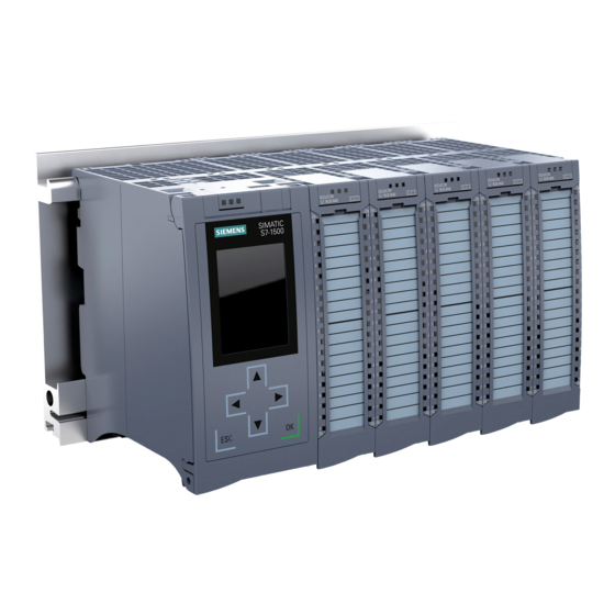
Product overview What is the S7-1500 Automation System? Introduction The SIMATIC S7-1500 is the further development of the SIMATIC S7-300 and S7-400 automation systems. Through the integration of numerous new performance features, the S7-1500 automation system offers the user excellent operability and the highest performance. The new performance features are: ●... - Page 14 Product overview 2.1 What is the S7-1500 Automation System? Configuration example The following figure shows a configuration example of an S7-1500 automation system. ① System power supply module ② ③ I/O modules ④ Mounting rail with integrated top-hat rail profile Figure 2-1 Example configuration of an S7-1500 automation system S7-1500 Automation System...
-
Page 15: Components
Product overview 2.2 Components Components Components of the S7-1500 automation system The following table provides an overview of the most important components of the S7-1500 automation system: Table 2- 1 Components of the S7-1500 automation system Components Function Diagram Mounting rail The mounting rail is the rack of the S7-1500 automation system. - Page 16 Product overview 2.2 Components Components Function Diagram The CPU executes the user program and uses the integrated system power supply to supply the electronics of the modules via the backplane bus. Further features and functions of the CPU: Communication via Ethernet •...
- Page 17 Product overview 2.2 Components Components Function Diagram Shielding bracket The shielding bracket is an insertable bracket for modules with EMC-critical signals (e.g., analog modules, technology modules), and (together with the shielding clamp) permits the low impedance application of shielding with minimal installation times. The shielding bracket is included in the scope of delivery of the analog and technology modules, and may be ordered as an accessory (Page 193).
-
Page 18: Properties
Product overview 2.3 Properties Properties Introduction The most important properties of the S7-1500 automation system are described in the following tables. Properties of the configuration Table 2- 2 Properties of the configuration Properties of the configuration Explanation Scalable configuration Space-saving because modules can be •... - Page 19 Product overview 2.3 Properties Properties of the connection technology Table 2- 3 Properties of the connection technology Properties of the connection technology Explanation Twistable front connector Rapid module exchange during maintenance • (cable duct remains closed) Pre-wiring position More user-friendly, because the module •...
- Page 20 Product overview 2.3 Properties S7-1500 Automation System System Manual, 01/2013, A5E03461182-01...
-
Page 21: Module Overview
Module overview The following tables summarize the essential properties of the available modules. This overview should make it easier for you to select the module that is suited to your task. Central processing units Overview of properties The table below shows the essential properties of the central processing units (CPUs). Table 3- 1 Central processing units Order no.:... -
Page 22: Digital Input Modules
Module overview 3.2 Digital input modules Digital input modules Overview of properties The table below shows the essential properties of the digital input modules. Table 3- 2 Digital input modules Order no.: 6ES7521-1BH00-0AB0 6ES7521-1BL00-0AB0 6ES7521-1BH50-0AA0 6ES7521-1FH00-0AA0 Short description DI 16x24VDC HF DI 32x24VDC HF DI 16x24VDC SRC BA DI 16x230VAC BA... -
Page 23: Digital Output Modules
Module overview 3.3 Digital output modules Digital output modules Overview of properties The table below shows the essential properties of the digital output modules. Table 3- 3 Digital output modules Order no.: 6ES7522-1BH00-0AB0 6ES7522-1BL00-0AB0 6ES7522-1BF00-0AB0 Short description DQ 16x24VDC/0.5A ST DQ 32x24VDC/0.5A ST DQ 8x24VDC/2A HF Number of outputs... -
Page 24: Analog Input Modules
Module overview 3.4 Analog input modules Analog input modules Overview of properties The table below shows the essential properties of the analog input modules. Table 3- 5 Analog input modules Order no.: 6ES7531-7KF00-0AB0 6ES7531-7NF10-0AB0 Short description AI 8xU/I/RTD/TC ST AI 8xU/I HS Number of inputs Resolution 16 bits (including sign) -
Page 25: Analog Output Modules
Module overview 3.5 Analog output modules Analog output modules Overview of properties The table below shows the essential properties of the analog output modules. Table 3- 6 Analog output modules Order no.: 6ES7532-5HD00-0AB0 6ES7532-5HF00-0AB0 Short description AQ 4xU/I ST AQ 8xU/I HS Number of outputs Resolution 16 bits (including sign) -
Page 26: Load Current Supply Modules
Module overview 3.7 Load current supply modules Load current supply modules Overview of properties The table below shows the essential properties of the load current supplies. Table 3- 8 Load current supply modules Order no.: 6EP1332-4BA00 6EP1333-4BA00 Short description PM 70W 120/230V AC PM 190W 120/230V AC Rated input voltage 120/230 VAC, with automatic... -
Page 27: Technology Modules
Module overview 3.8 Technology modules Technology modules Overview of properties The table below shows the essential properties of the technology modules. Table 3- 9 Technology modules Order no.: 6ES7550-1AA0-0AB0 6ES7551-1AB00-0AB0 Short description TM Count 2x24V TM PosInput 2 Supported encoders Incremental encoder for signals, Incremental encoder for signals to RS422 24 V asymmetric,... -
Page 28: Communication Modules
Module overview 3.9 Communication modules Communication modules Overview of properties The table below shows the essential properties of the communication modules. Table 3- 10 Communication modules for point-to-point linking Order no.: 6ES7540-1AD00-0AA0 6ES7540-1AB00-0AA0 6ES7541-1AD00-0AB0 6ES7541-1AB00-0AB0 Short description CM PtP RS232 BA CM PtP RS422/485 BA CM PtP RS232 HF CM PtP RS422/485 HF... -
Page 29: Application Planning
Application planning Hardware configuration Introduction The configuration of an S7-1500 automation system consists of a single-row configuration, in which all modules are installed on a mounting rail. The modules are connected by means of U connectors, and thus form a self-assembling backplane bus. Rule An S7-1500 automation system consists of a maximum of 32 modules, which occupy slots 0 to 31. - Page 30 Application planning 4.1 Hardware configuration Appropriate modules The following table shows which modules may be used in the various slots: Module type Permissible slots Number of modules System power supply (PS) 0; 2 - 31 Max. 3 I/O modules 2 - 31 Max.
-
Page 31: System And Load Power Supply
Application planning 4.2 System and load power supply System and load power supply In the S7-1500 automation system, you must make a distinction between two different power supplies: ● System power supply (PS) The system power supply has a connection to the backplane bus (U-connector) and supplies solely the internally required system voltage for the backplane bus. -
Page 32: Use Of System Power Supplies
Application planning 4.2 System and load power supply 4.2.1 Use of system power supplies System power supplies are required, if the power fed from the CPU into the backplane bus is not sufficient to supply all connected modules with power. In addition, you can use the system power supply with 120/230 VAC and supply the CPU through the backplane bus. -
Page 33: Special Considerations For The Use Of A System Power Supply In The First Power Segment
Further information on the performance values (power feed, power consumption) of the CPU, of the system power supply, and of the I/O modules can be found in the Manuals (http://support.automation.siemens.com/WW/view/en/57251228) of the respective modules. 4.2.2 Special considerations for the use of a system power supply in the first power... - Page 34 Application planning 4.2 System and load power supply Infeed via CPU and system power supply For larger hardware configurations, infeed into the backplane bus by the CPU alone no longer suffices. If then modules in total consume more than 10 or 12 W, insert an additional system power supply.
-
Page 35: Power Balance Calculation
The power fed into the backplane bus from the CPU and system power supply is listed in the technical data of the CPU in the corresponding Manual (http://support.automation.siemens.com/WW/view/en/57251228). The power drawn from the backplane bus by an I/O module or the CPU is listed in the technical data of the CPU in the corresponding Manual (http://support.automation.siemens.com/WW/view/en/57251228). - Page 36 Application planning 4.3 Power balance calculation Power balance calculation during planning with STEP 7 Compliance with the power balance is reviewed during planning by STEP 7. Proceed as follows to evaluate the power balance calculation: 1. Configure the configuration of the S7-1500 with all the required modules. 2.
-
Page 37: Use Of Load Power Supplies
Supply of the modules from 24 VDC load power supply Reference Further information on load power supplies can be found on the Internet (http://www.siemens.com/industrymall) in the online catalog and/or in the online ordering system. S7-1500 Automation System System Manual, 01/2013, A5E03461182-01... - Page 38 Application planning 4.4 Use of load power supplies S7-1500 Automation System System Manual, 01/2013, A5E03461182-01...
-
Page 39: Installation
Installation Basics Introduction All modules of the S7-1500 automation system are unenclosed equipment. This means that you may only install this system in housings, cabinets or electrical operating rooms. These housings, cabinets or electrical operating rooms must only be accessible with a key or tool. Access may only be possible for instructed or authorized personnel. - Page 40 Installation 5.1 Basics Minimum clearances Modules can be mounted up to the outer edge of the mounting rail. Maintain the following minimum clearances at the top and bottom when installing or removing the S7-1500 automation system. ① Upper edge of the mounting rail Figure 5-1 Minimum clearances in the control cabinet Installation rules...
-
Page 41: Installing The Mounting Rail
Installation 5.2 Installing the mounting rail Installing the mounting rail Introduction The mounting rails are delivered in five lengths: ● 160 mm ● 482.6 mm (19 inches) ● 530 mm ● 830 mm ● 2000 mm The order numbers can be found in the Accessories/spare parts (Page 193) section. The mounting rails (from 160 to 830 mm) come with two drill holes for fixing screws. - Page 42 Installation 5.2 Installing the mounting rail Dimensions for the drill holes The following table contains the dimensions for the mounting rail drill holes. Table 5- 2 Dimensions for the drill holes "Standard" mounting rails "Longer" mounting rails Length of the mounting rail Distance a Distance b 160 mm 10 mm...
- Page 43 Installation 5.2 Installing the mounting rail Preparing the 2000 mm mounting rail for installation 1. Cut the 2000 mm mounting rail to the required length. 2. Mark the holes. The necessary dimensions can be found in the above-mentioned table "Dimensions for the drill holes": –...
- Page 44 Installation 5.2 Installing the mounting rail Attaching the protective conductor The S7-1500 automation system has to be connected to the protective conductor system of the electrical system to ensure electrical safety. 1. Strip the grounding conductor with a minimum diameter of 10 mm and attach a ring terminal for size M6 bolts with the crimping pliers.
-
Page 45: Mounting A System Power Supply Module
Installation 5.3 Mounting a system power supply module Mounting a system power supply module Introduction The system power supply module has a connection to the backplane bus and supplies the configured modules with the internal supply voltage. Requirements The mounting rail is installed. Tools required Screwdriver with 4.5 mm blade Mounting a system power supply module... - Page 46 Installation 5.3 Mounting a system power supply module Dismantling a system power supply module The system power supply is wired up. 1. Turn off the fed supply voltage. 2. Open the front cover. 3. Shut down the system power supply. 4.
-
Page 47: Mounting A Load Current Supply Module
Installation 5.4 Mounting a load current supply module Mounting a load current supply module Introduction Load current supplies do not have a connection to the backplane bus of the S7-1500 automation systems and therefore do not use a configurable slot. The system power supply, CPU, input and output circuits of the I/O modules and, if applicable, the sensor technology and final controlling elements are supplied with 24 VDC through the load current supply. - Page 48 Installation 5.4 Mounting a load current supply module For a description on how to wire the power cable connector refer to the section Connecting the system power supply and load current supply modules (Page 62). Note Load current supplies can be mounted to the left or right of the configured setup. If you mount a load current supply on the right of the configured setup, the heat development of the load current supply may make a gap to the configured setup necessary.
-
Page 49: Installing The Cpu
Installation 5.5 Installing the CPU Installing the CPU Introduction The CPU executes the user program and uses the integrated system power supply to supply the electronics of the modules via the backplane bus. Requirements The following preconditions have to be fulfilled to mount a CPU: ●... - Page 50 Installation 5.5 Installing the CPU Uninstalling the CPU The CPU is wired, and is followed by additional modules. 1. Open the front cover. 2. Switch the CPU into STOP mode. 3. Turn off the fed supply voltage. 4. Pull off the connector for the supply voltage. 5.
-
Page 51: Installing I/O Modules
Installation 5.6 Installing I/O modules Installing I/O modules Introduction The I/O modules are installed following the CPU. I/O modules form the interface between the controller and the process. The controller detects the current process state via the connected sensors and actuators, and triggers the corresponding reactions. Requirements The following preconditions have to be fulfilled to mount an I/O module: ●... - Page 52 Installation 5.6 Installing I/O modules Uninstalling I/O modules The I/O module is wired. Proceed as follows to dismantle an I/O module: 1. Turn off all fed supply voltages. 2. Open the front cover. 3. For communication modules: Loosen and remove the connector from the module. At I/O modules: Pull the front connector out of the I/O module using the unlocking strap.
-
Page 53: Wiring
Wiring Rules and regulations for operation Introduction As part of plants and/or systems, the S7-1500 automation system requires adherence to special rules and regulations, depending on the field of application. This section provides an overview of the most important rules that must be observed for the integration of the S7-1500 CPU in a plant or system. - Page 54 ● Overvoltage arresters are to be used as protection against lightning and overvoltages. Suitable components for the lightning and overvoltage protection are specified in the Defining interference-free controllers (http://support.automation.siemens.com/WW/view/en/59193566) function manual. Protection against electrical shock The mounting rail of the S7-1500 automation system has to be connected conductively with the protective conductor as protection against electrical shock.
-
Page 55: Operating The S7-1500 On Grounded Infeed
Wiring 6.2 Operating the S7-1500 on grounded infeed Operating the S7-1500 on grounded infeed Introduction The following provides information on the overall configuration of an S7-1500 on a grounded infeed (TN-S network). The specific subjects discussed are: ● Disconnecting devices, short-circuit and overload protection to IEC 60364 (corresponding to DIN VDE 0100) and IEC 60204 (corresponding to DIN VDE 0113). - Page 56 Wiring 6.2 Operating the S7-1500 on grounded infeed Short-circuit and overload protection Various measures as protection against short-circuits and overloads are required for setting up a full installation. The nature of the components and the degree to which the required measures are binding depends on the IEC (DIN VDE) regulation applicable to your plant configuration.
- Page 57 Wiring 6.2 Operating the S7-1500 on grounded infeed S7-1500 in the overall configuration The figure below shows the overall configuration of the S7-1500 (load voltage supply and grounding concept) with infeed from a TN-S network. ① Main switch ② Short-circuit and overload protection on the primary side ③...
-
Page 58: Electrical Configuration Of The S7-1500
Wiring 6.3 Electrical configuration of the S7-1500 Electrical configuration of the S7-1500 Electrical isolation With the S7-1500, there is electrical isolation between: ● The primary side of the system power supply (PS) and all other circuit components ● the (PROFIBUS/PROFINET) communication interfaces of the CPU and all other circuit components ●... -
Page 59: Wiring Rules
Wiring 6.4 Wiring rules Wiring rules Wiring rules Table 6- 2 Wiring rules Wiring rules for... 40-pin front connector System power and load (screw-type connection) current supply Connectible conductor cross-sections for up to 0.25 mm solid wires up to 24 Connectible Without end sleeve 0.25 to 1.5 mm... -
Page 60: Connect Supply Voltage To The Cpu
Wiring 6.5 Connect supply voltage to the CPU Connect supply voltage to the CPU Introduction The supply voltage of the CPU is supplied by means of a 4-pole cable connector, which is located on the front of the CPU. Connection for supply voltage The connections of the 4-pole connector have the following meaning: ①... - Page 61 Wiring 6.5 Connect supply voltage to the CPU Connection of wires: multi-wire (stranded), without end sleeve, unprocessed 1. Strip 8 to 11 mm of the wires. 2. Using a screwdriver, press the spring release and insert the wire into the push-in terminal as far as it will go.
-
Page 62: Connecting The System Power Supply And Load Current Supply Modules
Wiring 6.6 Connecting the system power supply and load current supply modules Connecting the system power supply and load current supply modules Introduction In the delivery state of the system power supply and load current supply modules, power connectors are inserted. The modules and the associated power connectors are coded. The coding is effected by means of two coding elements - one coding element is located in the module, and the other in the power connector. -
Page 63: Connect Interfaces For Communication
Wiring 6.7 Connect interfaces for communication 6. Connect the wires in the connector according to the connection diagram (Figure 4). 7. Close the cover (Figure 5). 8. Retighten the screw (Figure 6). This effects a strain relief on the lines. Figure 6-5 Connecting the supply voltage to the system power supply and load current supply modules (2) -
Page 64: Front Connector For The I/O Modules
Wiring 6.8 Front connector for the I/O modules Front connector for the I/O modules 6.8.1 Characteristics of the front connector Introduction The sensors and actuators of your plant are connected to the S7-1500 automation system by means of front connectors. Wire the sensors and actuators to the front connector and then plug it into the I/O module. -
Page 65: Wiring Front Connectors For I/O Modules Without Shield Contact Element
Wiring 6.8 Front connector for the I/O modules ● In the delivery state a coding element is located in the module. When the front connector is first inserted into the I/O module, a part of the coding element clips onto the front connector. - Page 66 Wiring 6.8 Front connector for the I/O modules Preparing and wiring front connectors for I/O modules without shield contact element Proceed as follows to wire the front connector: 1. As needed, switch off the load power supply. 2. Swing the front cover of the wired I/O module up until the front cover latches (Figure 1). 3.
- Page 67 Wiring 6.8 Front connector for the I/O modules Use of the potential bridges at digital modules With the delivered potential bridges, for digital modules with a maximum rated voltage of 24 V DC, you can bridge the terminals for the voltage supply and thus reduce the wiring effort.
-
Page 68: Wiring Front Connectors For I/O Modules With Shield Contact Element
Wiring 6.8 Front connector for the I/O modules 6.8.3 Wiring front connectors for I/O modules with shield contact element Requirements ● I/O modules are installed on the mounting rail. ● The supply voltage is turned off. ● The wires are prepared according to the utilized clamping technology, take the wiring rules (Page 59) into account to this purpose. - Page 69 Wiring 6.8 Front connector for the I/O modules Preparing front connectors for I/O modules with shield contact element 1. Remove the connection separator from the lower part of the connector (Figure 1). 2. Insert the power supply element (Figure 2). 3.
- Page 70 Wiring 6.8 Front connector for the I/O modules 6. Bring the front connector into the pre-wiring position. To do this, hook the front connector into the bottom of the I/O module and swivel it upwards until the front connector latches (Figure 6).
- Page 71 Wiring 6.8 Front connector for the I/O modules 7. Wire the power supply element (Figure 8). Terminals 41/42 and 43/44 are galvanically connected to each other. If you connect the supply voltage to 41 (L+) and 44 (M), then with terminals 42 (L+) and 43 (M) you can loop the potential to the next module.
- Page 72 Wiring 6.8 Front connector for the I/O modules Wiring front connectors for I/O modules with shield contact element 1. Strip the cable shielding. 2. Begin to completely wire the front connector (Figure 1). Figure 6-12 Wiring front connectors for I/O modules with shield contact element (1) 3.
- Page 73 Wiring 6.8 Front connector for the I/O modules 4. Insert the shield clamp from below into the shielding bracket in order to connect the cable shielding (Figure 3). Figure 6-14 Wiring front connectors for I/O modules with shield contact element (3) Functions of the shield contact The shield contact: ●...
-
Page 74: Bringing The Front Connector Into Final Position
Wiring 6.8 Front connector for the I/O modules 6.8.4 Bringing the front connector into final position Bring the front connector from the pre-wiring position into final position Proceed as follows to bring the front connector from the pre-wiring position into final position: 1. - Page 75 Wiring 6.8 Front connector for the I/O modules Bringing the front connector directly into final position Proceed as follows to bring the front connector directly into final position: 1. Grip the front connector by the unlocking strap. 2. Push the guide pin of the front connector into the guide channel that has been displaced downwards.
-
Page 76: Marking The I/O Modules
Wiring 6.9 Marking the I/O modules Marking the I/O modules 6.9.1 Labeling strips Introduction Mark the pin assignment of the I/O modules using labeling strips. The labeling strip can be written on as desired, and is slid into the outside of the front cover. The labeling strips are available in the following models: ●... -
Page 77: Optional Marking
Wiring 6.9 Marking the I/O modules 6.9.2 Optional marking Introduction On the I/O modules there is free space on the front cover, that permits an additional labeling or marking on the part of the customer. Optional marking The front cover provides about 30 mm x 10 mm of space in its lower part for an optional identifier label. - Page 78 Wiring 6.9 Marking the I/O modules S7-1500 Automation System System Manual, 01/2013, A5E03461182-01...
-
Page 79: Configuring
Configuring In order that the S7-1500 automation system knows how it is to be configured (preset configuration) and how it is to operate, you must configure the individual hardware components, assign parameters to them, and connect them to each other. The work needed for this is undertaken in the device and network view in STEP 7. - Page 80 Configuring Reading out the configuration of an existing station When a connection exists to a CPU, you can load the configuration of this CPU (including possibly present modules) from the device into your project. To do this, create a new project and configure an "Unspecified CPU". Figure 7-1 Unspecified S7-1500 CPU in the device view In the device view (or in the network view), select the "Hardware detection"...
- Page 81 Configuring After you have selected the CPU in the "Hardware detection for PLC_x" dialog, and have clicked the "Detect" button, STEP 7 loads the hardware configuration (including modules) from the CPU into your project. Figure 7-4 Result of the hardware detection in the device view S7-1500 Automation System System Manual, 01/2013, A5E03461182-01...
- Page 82 Configuring STEP 7 assigns a valid default parameter assignments for all modules. You can change the parameter assignment subsequently. Properties of central modules The properties of the CPUs have special significance for system behavior. You can set the following, for example, at a CPU in STEP 7: ●...
-
Page 83: Address Assignment
Configuring 7.1 Address assignment Address assignment 7.1.1 Addressing - Overview Introduction In order to address the automation components or I/O modules, unique addresses must be assigned to them. The various address areas are explained below. I/O address I/O addresses (input/output addresses) are required to read inputs and set outputs in the user program. - Page 84 Configuring 7.1 Address assignment Hardware identifier In addition to the I/O addresses, a hardware identifier (Hardware identifier), which is used to identify the module, is assigned automatically by STEP 7. Such a Hardware identifier is also assigned to submodules. The Hardware identifier consists of an integer and is output at diagnostic messages by the system.
-
Page 85: Addressing Digital Modules
Configuring 7.1 Address assignment 7.1.2 Addressing digital modules Introduction The addressing of digital modules is described below. In your user program, you require the addresses of the channels of the digital module. Digital module addresses The address of a digital module's input or output is composed of the byte address and the bit address. - Page 86 Configuring 7.1 Address assignment Example for the assignment of channel addresses (digital module) The following figure shows how the addresses of the individual channels of the digital input module (e.g., 6ES7521-1BL00-0AB0) are determined. Figure 7-8 Example for the assignment of channel addresses (digital module) Note You can also assign symbolic names to the addresses in STEP 7's PLC tag table.
-
Page 87: Addressing Analog Modules
Configuring 7.1 Address assignment 7.1.3 Addressing analog modules Introduction The addressing of analog modules is described below. In your user program, you require the addresses of the channels of the analog module. Analog module addresses The address of an analog channel is always a word address. The channel address depends on the module start address. - Page 88 Configuring 7.1 Address assignment Example for the assignment of channel addresses (analog module) The following figure shows how the addresses of the of the individual channels of the analog input module (e.g., 6ES7531-7NF10-0AB0) are determined, when the module has the start address 256.
-
Page 89: Process Images And Process Image Partitions
Configuring 7.2 Process images and process image partitions Process images and process image partitions 7.2.1 Process image - overview Process image of the inputs and outputs When the user program addresses the input (I) and output (O) operand areas, it does not query the signal states directly from the I/O modules. -
Page 90: Automatically Update Process Image Partitions
Configuring 7.2 Process images and process image partitions 7.2.2 Automatically update process image partitions One process image partition can be assigned to each organization block. In this case, the process image partition is automatically updated. The exceptions are PIP 0 and isochronous OBs. - Page 91 Configuring 7.2 Process images and process image partitions Reference Additional information on process image partitions is available found in the function manual, Cycle and response times (http://support.automation.siemens.com/WW/view/en/59193558). S7-1500 Automation System System Manual, 01/2013, A5E03461182-01...
- Page 92 Configuring 7.2 Process images and process image partitions S7-1500 Automation System System Manual, 01/2013, A5E03461182-01...
-
Page 93: Commissioning
Commissioning Commissioning S7-1500 - overview Introduction In this section you will find summary information about the necessary steps for commissioning an S7-1500. Commissioning requirements Note You must ensure the safety of your plant. Therefore, you must perform a complete functional test and the necessary safety checks before commissioning a plant. -
Page 94: Review Before The First Power-On
Commissioning 8.2 Review before the first power-on Review before the first power-on Review before the first power-on Before the first power-on check the installation and the wiring of the S7-1500 automation system. Questions for the review The following questions provide guidance for the review of your S7-1500 automation system in the form of a checklist. -
Page 95: Commissioning Procedure
Notes on the meaning of the LEDs can be found in the manuals of the modules, and in the System Diagnostics Function Manual (http://support.automation.siemens.com/WW/view/en/59192926). Evaluate information on the CPU's display See the section, Display of the CPU (Page 141) Configure hardware in STEP 7 and See the "Online and diagnostics"... - Page 96 – The CPU is connected to the subnet. – The terminating resistors at the segment boundaries are switched on. See the PROFIBUS Function Manual (http://support.automation.siemens.com/WW/view/en/59193579) ● PROFINET interface – The integrated PROFINET interface of the CPU is configured using STEP 7 (IP address and device name configured).
-
Page 97: Removing/Inserting The Simatic Memory Card
Commissioning 8.3 Commissioning procedure 8.3.1 Removing/inserting the SIMATIC memory card Requirements The CPU only supports pre-formatted SIMATIC memory cards. As applicable, delete all previously stored data before using the SIMATIC memory card. Additional information about deleting the contents of the SIMATIC memory card can be found in the section, SIMATIC memory card - overview (Page 135). -
Page 98: First Power-On
Commissioning 8.3 Commissioning procedure Reactions after removing/inserting the SIMATIC memory card When inserting and removing the SIMATIC memory card, the CPU automatically performs memory reset, and then goes into STOP mode. The CPU evaluates the SIMATIC memory card, and indicates this by flashing the RUN/STOP LED. -
Page 99: Operating Modes
Commissioning 8.4 Operating modes Operating modes Introduction Operating modes describe the states of the CPU. The following operating states are possible via the mode selector: ● STARTUP ● RUN ● STOP In these operating modes, the CPU can communicate, e.g. via the PN/IE interface. The status LEDs on the front side of the CPU indicate the current operating mode. - Page 100 Commissioning 8.4 Operating modes The following table shows the conditions under which the operating modes change: Table 8- 1 Operating mode conditions No. Operating mode Conditions transitions ① POWER ON → After switching on, the CPU goes into "STARTUP" mode, if: STARTUP The hardware configuration and program blocks are consistent.
- Page 101 Commissioning 8.4 Operating modes Setting the startup behavior Proceed as follows to set the startup behavior: 1. In the device view of the STEP 7 hardware network editor, select the CPU. 2. In the properties under "General" select the "Startup" area. Figure 8-3 Setting the startup behavior ①...
- Page 102 Commissioning 8.4 Operating modes Hardware compatibility Compatible means that the module matches the number of inputs and output and must match with respect to its electrical and functional properties. A compatible module must be fully able to replace a configured module; it may be more capable, but not less capable. In case of the "Startup of the CPU only if compatible"...
-
Page 103: Startup" Mode
Commissioning 8.4 Operating modes 8.4.2 "STARTUP" mode Function Before the CPU starts to execute the cyclic user program, a startup program is executed. By suitably programming startup OBs, you can specify initialization tags for your cyclic program in the startup program. That is, you can set up one or several startup OBs in your program, or none at all. -
Page 104: Stop" Mode
Commissioning 8.4 Operating modes Response when expected and actual configurations do not match The expected configuration is represented by the configuration loaded into the CPU. The actual configuration is the actual configuration of the automation system. If the expected configuration and actual configuration deviate from one another, then the CPU's behavior is specified by the setting of the hardware compatibility. -
Page 105: Run" Mode
Further events such as hardware interrupts and diagnostic interrupts can interrupt the cyclic program flow and prolong the cycle time. Reference Further information about cycle and response times is available in the Function Handbook Cycle and response times (http://support.automation.siemens.com/WW/view/en/59193558). S7-1500 Automation System System Manual, 01/2013, A5E03461182-01... -
Page 106: Memory Reset
Commissioning 8.5 Memory reset Memory reset Basics of a memory reset A memory reset on the CPU is possible only in the STOP operating mode. When memory is reset, the CPU is changed to a so-called "initial status". This means that: ●... -
Page 107: Automatic Memory Reset
Commissioning 8.5 Memory reset 8.5.1 Automatic memory reset Possible cause of automatic memory reset The CPU executes an automatic memory reset, if an error occurs that prevents normal further processing. Causes for such errors can be: ● User program is too large, and can't be completely loaded into work memory. ●... - Page 108 Commissioning 8.5 Memory reset Procedure using the operating mode switch Note Memory reset ↔ Reset to factory settings The selector operation described below also reflects the procedure for a memory reset: • Selector operation with inserted SIMATIC memory card: Memory reset is executed •...
-
Page 109: Identification And Maintenance Data
Commissioning 8.6 Identification and maintenance data Identification and maintenance data 8.6.1 Reading out and entering I&M data Introduction Identification and maintenance data (I&M data) is data saved on the module as read-only (I data) or read/write (M data) information. Identification data (I&M0): Manufacturer information about the module, that can only be read, and is in part also printed on the housing of the module, e.g., order number and serial number. - Page 110 Procedure for reading I&M data via the web server The procedure is extensively described in the Identification section of the Web Server Function Manual (http://support.automation.siemens.com/WW/view/en/59193560). Procedure for reading I&M data via STEP 7 Requirements: There must be an online connection to the CPU.
- Page 111 Commissioning 8.6 Identification and maintenance data Procedure for entering maintenance data via STEP 7 The default module name is assigned by STEP 7. You can enter the following information: ● Plant designation (I&M 1) ● Location identifier (I&M 1) ● Installation date (I&M 2) ●...
-
Page 112: Record Structure For I&M Data
Commissioning 8.6 Identification and maintenance data 8.6.2 Record structure for I&M data Reading I&M records (centrally and distributed via PROFINET IO) You can directly access specific identification data for a module using Read record ("RDREC" instruction). Under the associated record index you obtain the corresponding part of the identification data. - Page 113 Access Example Explanation Identification data 0: (record index AFF0 VendorIDHigh read (1 bytes) 0000 Vendor name (002A = SIEMENS AG) VendorIDLow read (1 bytes) 002A Order_ID read (20 bytes) 6ES7516-3AN00-0AB0 Order number of the module (e.g. CPU 1516-3 PN/DP) IM_SERIAL_NUMBER...
- Page 114 Commissioning 8.6 Identification and maintenance data Reading I&M records with record 255 (decentrally via PROFINET IO) The modules also support standardized access to the identification data via record 255 (index 65000 through 65003). Additional information on the data structure of record 255 can be found in the specifications of the PROFIBUS Guideline - order no.
-
Page 115: Maintenance
Maintenance Removing and inserting I/O modules Front connectors and I/O modules must only be inserted or removed when the voltage is switched off. NOTICE Physical damage can occur If you install or uninstall front connectors and/or I/O modules with switched-on voltage, this can lead to undefined conditions in your plant. -
Page 116: Replacement Of I/O Modules And Front Connectors
Maintenance 9.2 Replacement of I/O modules and front connectors Replacement of I/O modules and front connectors 9.2.1 Coding element on the I/O module and on the front connector Introduction All front connectors for the I/O modules of the S7-1500 automation system are identical. The coding element prevents a front connector from being inserted on a module with a different electrical pin assignment. - Page 117 Maintenance 9.2 Replacement of I/O modules and front connectors When the front connector is inserted into the I/O module for the first time, one half of the coding element latches into the front connector. When the front connector is removed from the I/O module, this half of the coding element remains in the front connector, while the other half remains in the I/O module.
-
Page 118: Replacing An I/O Module
Maintenance 9.2 Replacement of I/O modules and front connectors 9.2.2 Replacing an I/O module Introduction When the front connector is first inserted into the I/O module, a part of the coding element clips onto the front connector. When you replace an I/O module with the same type of module, the correct coding element is already present in the front connector. -
Page 119: Replacing A Front Connector
Maintenance 9.2 Replacement of I/O modules and front connectors 9.2.3 Replacing a front connector Introduction When the front connector is first inserted into the I/O module, a part of the coding element clips onto the front connector. When you replace a defective front connector with a new front connector, then you must transfer the coding element into the new front connector. -
Page 120: Replacing The Coding Element At The Power Connector Of The System Power And Load Current Supply
Maintenance 9.3 Replacing the coding element at the power connector of the system power and load current supply Replacing the coding element at the power connector of the system power and load current supply Introduction The coding consists of a 2-part coding element. Ex factory a part of the coding element is inserted into the back side of the power connector. - Page 121 Maintenance 9.3 Replacing the coding element at the power connector of the system power and load current supply Procedure 1. Orient yourself to the labeling on the power cable connection. Figure 9-6 Labeling on the power connector 2. Orient yourself to the red marking on the coding element. 3.
-
Page 122: Firmware Update
Requirements ● You have downloaded the file(s) for the firmware update from the Customer Support (http://www.siemens.com/automation/) web site. On this web site, select: Automation technology > Automation systems > SIMATIC industrial automation system > Controllers > SIMATIC S7 modular controllers >... - Page 123 Maintenance 9.4 Firmware update Procedure using STEP 7 Proceed as follows to perform an online firmware update via STEP 7: 1. Select the CPU or the module in the device view. 2. Select the "Online & diagnostics" command from the shortcut menu. 3.
- Page 124 Maintenance 9.4 Firmware update Special feature at a firmware update of analog modules If you want to carry out a firmware update for analog modules, you have to supply 24 VDC load supply to the module through the power supply element. Procedure 1.
-
Page 125: Resetting The Cpu To Factory Settings
Maintenance 9.5 Resetting the CPU to factory settings Resetting the CPU to factory settings With "Reset to factory settings" the CPU is restored to the "as-delivered condition". This means that all data that were internally stored in the CPU have been deleted. Recommendation: If you want to remove a PROFINET CPU and use it elsewhere with a different program, or put it into storage, then the CPU should be restored to the as-delivered condition. - Page 126 Maintenance 9.5 Resetting the CPU to factory settings Note The IP address of the CPU is also deleted when the CPU is reset to the factory settings through the mode selector. Procedure using the display Make sure that the CPU is in STOP mode (RUN/STOP LED lights up yellow). To navigate to the desired "Factory settings"...
- Page 127 Additional information on "Reset to factory settings" can be found in the Function Manual Structure and use of the CPU memory (http://support.automation.siemens.com/WW/view/en/59193101) in the section on memory areas and retentivity, and in the online help for STEP 7. S7-1500 Automation System...
- Page 128 Maintenance 9.5 Resetting the CPU to factory settings S7-1500 Automation System System Manual, 01/2013, A5E03461182-01...
-
Page 129: Test Functions And Fault Resolution
Test functions and fault resolution 10.1 Test functions Introduction You have the option of testing the operation of your user program on the CPU. You can then monitor signal states and values of tags and can assign values to tags to simulate specific situations in the running of the program. - Page 130 Test functions and fault resolution 10.1 Test functions Testing with watch tables The following functions are available in the watch table: ● Monitoring of tags This allows the current values of the individual tags of a user program or a CPU to be monitored on the programming device or PC.
- Page 131 Test functions and fault resolution 10.1 Test functions Testing with the force table The following functions are available in the force table. ● Monitoring of tags This allows the current values of the individual tags of a user program or a CPU to be displayed on the programming device or PC.
- Page 132 Further information on the test functions can be found in the STEP 7 online help. Further information about testing with trace and logic analyzer functions is available in the Function Manual Using the trace and logic analyzer function (http://support.automation.siemens.com/WW/view/en/64897128). S7-1500 Automation System System Manual, 01/2013, A5E03461182-01...
-
Page 133: Reading Out/Saving Service Data
Test functions and fault resolution 10.2 Reading out/saving service data 10.2 Reading out/saving service data Introduction In addition to the contents of the diagnostics buffer, the service data contain numerous additional data points about the internal status of the CPU. If a problem with the CPU should occur, that cannot otherwise be resolved, please send the service data to our Service &... - Page 134 Test functions and fault resolution 10.2 Reading out/saving service data S7-1500 Automation System System Manual, 01/2013, A5E03461182-01...
-
Page 135: Simatic Memory Card
SIMATIC memory card 11.1 SIMATIC memory card - overview Introduction The S7-1500 automation system uses a so-called SIMATIC memory card as the program memory. The SIMATIC memory card is a preformatted memory card compatible with the Windows file system. The memory card is available in different memory sizes and can be used for the following purposes: ●... - Page 136 SIMATIC memory card 11.1 SIMATIC memory card - overview Insertion of the SIMATIC memory card ① Serial number, e.g. SMC_06ea123c04 ② Product version, e.g., E:01 ③ Order number, e.g., 6ES7954-8LF01-0AA0 ④ Memory size, e.g., 24 MB ⑤ Slider for enabling write protection: Slider up: not write-protected •...
- Page 137 SIMATIC memory card 11.1 SIMATIC memory card - overview Table 11- 2 File structure File type Description S7_JOB.S7S Job file SIMATIC.HMI\Backup\*.psb Panel backup files SIMATICHMI_Backups_DMS. Protected files (required to use panel backup files in the TIA Portal) __LOG__ Protected system file (required in order to use the card) crdinfo.bin Protected system file (required in order to use the card) *.pdf, *.txt, *.csv, ..
- Page 138 SIMATIC memory card 11.1 SIMATIC memory card - overview Deleting the contents of the SIMATIC memory card You have the following options for deleting the contents of the SIMATIC memory card: ● delete files using Windows Explorer ● format with STEP 7 Note If you format the card with Windows utilities, you will render the SIMATIC memory card unusable as a storage medium for a CPU.
-
Page 139: Setting The Card Type
SIMATIC memory card 11.2 Setting the card type 11.2 Setting the card type Setting the card type You can use the SIMATIC memory card as a program card or as a firmware update card. To set the card type, insert the SIMATIC memory card in the programming device's card reader, and select the "SIMATIC Card Reader"... -
Page 140: Data Transfer With Simatic Memory Cards
SIMATIC memory card 11.3 Data transfer with SIMATIC memory cards 11.3 Data transfer with SIMATIC memory cards Transferring objects from the project to a SIMATIC memory card When the SIMATIC memory card is inserted into the programming device or into an external card reader, you can transfer objects as follows from the project tree (STEP 7) to the SIMATIC memory card: ●... -
Page 141: Display Of The Cpu
Display of the CPU Introduction The S7-1500 CPU has a front cover with a display and operating keys. Control data and status data can be displayed in various menus on the display, and numerous settings can be configured. You use the operating keys to navigate through the menus. Benefits The display of the CPU offers the following advantages: ●... - Page 142 Display of the CPU Display The following figures show an example view of the displays of a CPU 1516-3 PN/DP on the left and a CPU 1511-1 PN or CPU 1513-1 PN on the right. ① CPU status data ② Submenu names ③...
- Page 143 Display of the CPU ② Regarding : Submenu names The following table shows the available submenus of the display. Table 12- 2 Submenu names Main menu items Meaning Description Overview The "Overview" menu contains information about the properties of the CPU. Diagnostics The "Diagnostics"...
- Page 144 Display of the CPU Menu icons The following table shows the icons that are displayed in the menus. Table 12- 3 Menu icons Icon Meaning Editable menu item Select the desired language here. There is an alarm in the next lower level object. There is a fault in the next lower level object.
- Page 145 Display of the CPU Control keys The following keys are available on the CPU's display: ● Four arrow keys: "up", "down", "left", "right" ● An ESC key ● An OK key Figure 12-2 Control keys Note If the display is in Energy-saving mode or in Standby mode, this mode can be exited by pressing any key.
- Page 146 Display of the CPU Available language settings You can set the following languages separately for menu and message texts: ● German ● English ● French ● Spanish ● Italian ● Chinese The settings are carried out directly at the display in the "Display" menu or in STEP 7 in the hardware configuration of the CPU under User interface languages".
-
Page 147: Basics Of Program Processing
Basics of program processing 13.1 Events and OBs OB start events The occurrence of an OB start event results in the following reaction: ● If the event comes from an event source to which you have assigned an OB, this event triggers the execution of the assigned OB. - Page 148 Basics of program processing 13.1 Events and OBs The following table provides an overview of the OB start events, including the possible values for OB priority, possible OB numbers, default system reaction and number of OBs. The table is sorted in ascending order by OB numbers. Types of event sources Possible priorities Possible OB...
- Page 149 Basics of program processing 13.1 Events and OBs Assignment between event source and OBs The type of OB determines where you make the assignment between OB and event source: ● With hardware interrupts and isochronous mode interrupts, the assignment is made during the configuration of the hardware or when the OB is created.
-
Page 150: Cpu Overload Behavior
Basics of program processing 13.2 CPU overload behavior 13.2 CPU overload behavior Principle of CPU overload behavior For the event scenarios considered in the following section, it is assumed that you have assigned an OB to each event source and that these OBs have the same priority. The second condition, in particular, is only for the sake of a simplified representation. - Page 151 Basics of program processing 13.2 CPU overload behavior Threshold mechanism for time error OB request The OB parameter "Enable time error" is used to specify whether the time error interrupt should be called when a specific overload level is reached for similar events. If yes (check box selected), you use the OB parameter "Event threshold for time error"...
- Page 152 Basics of program processing 13.2 CPU overload behavior S7-1500 Automation System System Manual, 01/2013, A5E03461182-01...
-
Page 153: Protection
Protection 14.1 Overview of the protective functions of the CPU Introduction This chapter describes the following functions for protecting the S7-1500 automation system against unauthorized access: ● Access protection ● Know-how protection ● Copy protection ● Protection by locking the CPU Further measures for protecting the CPU The following measures additionally increase the protection against unauthorized accesses to functions and data of the S7-1500 CPU from external sources and via the network:... -
Page 154: Configuring Access Protection For The Cpu
Protection 14.2 Configuring access protection for the CPU 14.2 Configuring access protection for the CPU Introduction The CPU offers four access levels, in order to limit access to specific functions. By setting up the access levels and the passwords for a CPU, you limit the functions and memory areas that are accessible without entering a password. - Page 155 Protection 14.2 Configuring access protection for the CPU Note Configuring an access level does not replace know-how protection Configuring access levels prevents unauthorized changes to the CPU, by restricting download privileges. However, blocks on the SIMATIC memory card are not write- or read- protected.
-
Page 156: Using The Display To Configure Additional Access Protection
Protection 14.3 Using the display to configure additional access protection Behavior of a password-protected CPU during operation The CPU protection takes effect after the settings are downloaded in the CPU. Before an online function is executed, the necessary permission is checked and, if necessary, the user is prompted to enter a password. -
Page 157: Know-How Protection
Protection 14.4 Know-how protection 14.4 Know-how protection You can use know-how protection to protect one or more blocks of the OB, FB, FC type and global data blocks in your program from unauthorized access. You can enter a password in order to restrict access to a block. - Page 158 Protection 14.4 Know-how protection 4. Click the "Define" button to open the "Define password" dialog. Figure 14-4 Setting up block know-how protection (3) 5. Enter the new password in the "New password" field. Enter the same password in the "Confirm password" field. 6.
- Page 159 Protection 14.4 Know-how protection Removing block know-how protection 1. Select the block from which you want to remove know-how protection. 2. In the "Edit" menu, select the "Know-how protection" command to open the "Know-how protection" dialog. 3. Deactivate the "Hide code (Know-how protection)" check box. Figure 14-5 Removing block know-how protection (1) 4.
-
Page 160: Copy Protection
Protection 14.5 Copy protection 14.5 Copy protection Copy protection allows you to bind the program or the blocks to a specific SIMATIC memory card or CPU. Through the linking of the serial number of a SIMATIC memory card or of a CPU the use of this program or of this block is only possible in combination with a specific SIMATIC memory card or CPU. -
Page 161: Protection By Locking The Cpu
Protection 14.6 Protection by locking the CPU Removing copy protection 1. Remove any existing know-how protection (Page 157). 2. Open the properties of the respective block. 3. Select the "Protection" option under "General". 4. In the "Copy protection" area, select the "No binding" entry from the drop-down list. Figure 14-10 Removing copy protection 14.6 Protection by locking the CPU... - Page 162 Protection 14.6 Protection by locking the CPU S7-1500 Automation System System Manual, 01/2013, A5E03461182-01...
-
Page 163: Technical Specifications
In the event of deviations between the statements in this document and the manuals, the statements in the product manuals take priority. Reference The certificates for the markings and approvals can be found on the Internet under Service&Support (http://www.siemens.com/automation/service&support). S7-1500 Automation System System Manual, 01/2013, A5E03461182-01... - Page 164 ● 94/9/EC on "equipment and protective systems for use in hazardous areas" (explosion protection directive) The EC declaration of conformity is held on file available to competent authorities at: Siemens Aktiengesellschaft Industry Sector I IA AS FA WF AMB Postfach 1963...
- Page 165 Technical specifications 15.1 Standards and Approvals cULus approval Underwriters Laboratories Inc. in accordance with ● UL 508 (Industrial Control Equipment) ● C22.2 No. 142 (Process Control Equipment) cuLus HAZ LOC approval Underwriters Laboratories Inc. in accordance with ● UL 508 (Industrial Control Equipment) ●...
- Page 166 Technical specifications 15.1 Standards and Approvals ATEX approval In accordance with EN 60079-15 (Electrical apparatus for potentially explosive atmospheres; Type of protection "n") and EN 60079-0 (Electrical apparatus for potentially explosive gas atmospheres - Part 0: General Requirements) Tick mark for Australia and New Zealand The S7-1500 automation system meets the requirements of the standard AS/NZS CISPR 16.
- Page 167 Technical specifications 15.1 Standards and Approvals Use in residential areas Note The S7-1500 automation system is intended for use in industrial areas; use in residential areas may have an impact on radio/TV reception. If you want to use the S7-1500 automation system in residential areas, you must ensure that its radio interference emission complies with limit value class B in accordance with EN 55011.
-
Page 168: Electromagnetic Compatibility
±1 kV (signal lines < 30 m) High-energy single pulse (surge) in accordance with IEC 61000-4-5 External protective circuit required (not for 230 V modules) (see the Defining interference-free controllers (http://support.automation.siemens.com/WW/view/en/59193566) Function Manual) ±2 kV (power supply lines) asymmetric coupling •... - Page 169 Technical specifications 15.2 Electromagnetic compatibility Sinusoidal disturbances The following table shows the electromagnetic compatibility of the S7-1500 automation system with regard to sinusoidal disturbances (RF radiation). Table 15- 3 Sinusoidal disturbances with RF radiation RF radiation in accordance with IEC 61000-4-3/NAMUR 21 corresponds with degree of severity Electromagnetic RF field, amplitude-modulated...
-
Page 170: Shipping And Storage Conditions
Technical specifications 15.3 Shipping and storage conditions 15.3 Shipping and storage conditions Introduction With respect to transportation and storage conditions, the S7-1500 automation system fulfills the requirements in accordance with IEC 61131-2. The following statements apply to modules that are transported and stored in the original packaging. Shipping and storage conditions for modules Table 15- 7 Shipping and storage conditions for modules... -
Page 171: Mechanical And Climatic Ambient Conditions
Technical specifications 15.4 Mechanical and climatic ambient conditions 15.4 Mechanical and climatic ambient conditions Operating conditions The S7-1500 automation system is suitable for use in weather-proof, fixed locations. The operating conditions exceed requirements according to DIN IEC 60721-3-3: ● Class 3M3 (mechanical requirements) ●... - Page 172 Technical specifications 15.4 Mechanical and climatic ambient conditions Climatic ambient conditions The S7-1500 automation system may be used in the following climatic ambient conditions: Table 15- 9 Climatic ambient conditions Ambient conditions Permissible range Comments Temperature: In order to increase the service life of the horizontal mounting 0 °C to 60 °C display, the display switches off before the...
-
Page 173: 15.5 Information On Insulation Tests, Protection Class, Degree Of Protection And Rated Voltage
Technical specifications 15.5 Information on insulation tests, protection class, degree of protection and rated voltage 15.5 Information on insulation tests, protection class, degree of protection and rated voltage Insulation The insulation is designed in accordance with the requirements of EN 61131-2: 2007. Note For modules with 24 VDC supply voltage, the electrical isolation is designed for max. -
Page 174: Use Of The S7-1500 In Zone 2 Potentially Explosive Atmospheres
Static value: Creation as functional extra-low voltage with safe electrical isolation in accordance with IEC 60364-4-41. 15.6 Use of the S7-1500 in Zone 2 potentially explosive atmospheres See product information Deployment of the modules in zone 2 potentially explosive atmospheres (http://support.automation.siemens.com/WW/view/en/19692172). S7-1500 Automation System System Manual, 01/2013, A5E03461182-01... -
Page 175: Dimension Drawings
Dimension drawings Dimension drawings of the mounting rails In this appendix you will find the dimension drawings of the mounting rails. Mounting rail 160 mm Figure A-1 Mounting rail 160 mm S7-1500 Automation System System Manual, 01/2013, A5E03461182-01... - Page 176 Dimension drawings A.1 Dimension drawings of the mounting rails Mounting rail 482.6 mm Figure A-2 Mounting rail 482.6 mm Mounting rail 530 mm Figure A-3 Mounting rail 530 mm S7-1500 Automation System System Manual, 01/2013, A5E03461182-01...
- Page 177 Dimension drawings A.1 Dimension drawings of the mounting rails Mounting rail 830 mm Figure A-4 Mounting rail 830 mm Mounting rail 2000 mm Figure A-5 Mounting rail 2000 mm S7-1500 Automation System System Manual, 01/2013, A5E03461182-01...
-
Page 178: Dimension Drawing Of Cpu, 35 Mm Wide
Dimension drawings A.2 Dimension drawing of CPU, 35 mm wide Dimension drawing of CPU, 35 mm wide In this appendix you will find the dimension drawing of the CPU installed on a mounting rail, as well as a dimension drawing with open front cover. Always observe the specified dimensions for installation in cabinets, control rooms, etc. -
Page 179: Dimension Drawing Of Cpu, 70 Mm Wide
Dimension drawings A.3 Dimension drawing of CPU, 70 mm wide Dimension drawing of CPU, 70 mm wide In this appendix you will find the dimension drawing of the CPU installed on a mounting rail, as well as a dimension drawing with open front cover. Always observe the specified dimensions for installation in cabinets, control rooms, etc. -
Page 180: Dimension Drawing Of I/O Module
Dimension drawings A.4 Dimension drawing of I/O module Dimension drawing of I/O module In this appendix you will find the dimension drawing of the module installed on a mounting rail, as well as a dimension drawing with open front cover. Always observe the specified dimensions for installation in cabinets, control rooms, etc. -
Page 181: Dimension Drawing Of I/O Module With Shield Contact Element
Dimension drawings A.5 Dimension drawing of I/O module with shield contact element Note Minimum clearances Observe the minimum clearances of 25 mm, above and below the mounting rail, as described in the chapterMounting (Page 39). Dimension drawing of I/O module with shield contact element Dimension drawing of I/O module with shield contact element The following figures show an I/O module with shield contact element, in front and side view. - Page 182 Dimension drawings A.5 Dimension drawing of I/O module with shield contact element Figure A-13 Dimension drawing of I/O module with shield connection element, side view with open front cover Note Minimum clearances Observe the minimum clearances of 25 mm, above and below the mounting rail, as described in the chapterMounting (Page 39).
-
Page 183: Dimension Drawing Of System Power Supply, 35 Mm Wide
Dimension drawings A.6 Dimension drawing of system power supply, 35 mm wide Dimension drawing of system power supply, 35 mm wide In this appendix you will find the dimension drawing of the system power supply installed on a mounting rail, as well as a dimension drawing with open front cover. Always observe the specified dimensions for installation in cabinets, control rooms, etc. -
Page 184: Dimension Drawing Of System Power Supply, 70 Mm Wide
Dimension drawings A.7 Dimension drawing of system power supply, 70 mm wide Note Minimum clearances Observe the minimum clearances of 25 mm, above and below the mounting rail, as described in the chapterMounting (Page 39). Dimension drawing of system power supply, 70 mm wide In this appendix you will find the dimension drawing of the system power supply installed on a mounting rail, as well as a dimension drawing with open front cover. - Page 185 Dimension drawings A.7 Dimension drawing of system power supply, 70 mm wide Figure A-17 Dimension drawing of system power supply (70 mm wide), side view with open front cover Note Minimum clearances Observe the minimum clearances of 25 mm, above and below the mounting rail, as described in the chapterMounting (Page 39).
-
Page 186: Dimension Drawing Of Load Power Supply, 50 Mm Wide
Dimension drawings A.8 Dimension drawing of load power supply, 50 mm wide Dimension drawing of load power supply, 50 mm wide In this appendix you will find the dimension drawing of the load power supply installed on a mounting rail, as well as a dimension drawing with open front cover. Always observe the specified dimensions for installation in cabinets, control rooms, etc. -
Page 187: Dimension Drawing Of Load Power Supply, 75 Mm Wide
Dimension drawings A.9 Dimension drawing of load power supply, 75 mm wide Note Minimum clearances Observe the minimum clearances of 25 mm, above and below the mounting rail, as described in the chapterMounting (Page 39). Dimension drawing of load power supply, 75 mm wide In this appendix you will find the dimension drawing of the load power supply installed on a mounting rail, as well as a dimension drawing with open front cover. - Page 188 Dimension drawings A.9 Dimension drawing of load power supply, 75 mm wide Figure A-21 Dimension drawing of load current supply (75 mm wide), side view with open front cover Note Minimum clearances Observe the minimum clearances of 25 mm, above and below the mounting rail, as described in the chapterMounting (Page 39).
-
Page 189: Dimension Drawing Of The Shielding Bracket
Dimension drawings A.10 Dimension drawing of the shielding bracket A.10 Dimension drawing of the shielding bracket In this appendix you will find the dimension drawing of the shielding bracket in front and side view. Figure A-22 Dimension drawing of the shielding bracket A.11 Dimension drawing of the shield clamp In this appendix you will find the dimension drawing of the shield clamp in front and side... -
Page 190: Dimension Drawing Of The Power Supply Element
Dimension drawings A.12 Dimension drawing of the power supply element A.12 Dimension drawing of the power supply element In this appendix you will find the dimension drawing of the power supply element in front and side view. Figure A-24 Dimension drawing of the power supply element A.13 Dimension drawing of the labeling strip In this appendix you will find the dimension drawing of the labeling strip. -
Page 191: Dimensional Drawing Of Communication Module
Dimension drawings A.14 Dimensional drawing of communication module A.14 Dimensional drawing of communication module This appendix contains the dimensional drawing of the communication module installed on a mounting rail and with a shield bracket. Always observe the specified dimensions for installation in cabinets, control rooms, etc. - Page 192 Dimension drawings A.14 Dimensional drawing of communication module Figure A-27 Dimension drawing of communication module, side view with open front cover S7-1500 Automation System System Manual, 01/2013, A5E03461182-01...
-
Page 193: Accessories/Spare Parts
Accessories/spare parts Accessories for the S7-1500 automation system Table B- 1 Accessories for the S7-1500 automation system Description Order number Mounting rail 6ES7590-1AB60-0AA0 Mounting rail, 160 mm (with drill holes) • 6ES7590-1AE80-0AA0 Mounting rail, 482 mm (with drill holes) • 6ES7590-1AF30-0AA0 Mounting rail, 530 mm (with drill holes) •... - Page 194 4 MB 6ES7954-8LExx-0AA0 12 MB 6ES7954-8LFxx-0AA0 24 MB Online catalog Additional order numbers for the S7-1500 automation system can be found on the Internet (http://www.siemens.com/industrymall) in the online catalog and online ordering system. S7-1500 Automation System System Manual, 01/2013, A5E03461182-01...
-
Page 195: Service & Support
Our Service & Support accompanies you worldwide in all matters concerning automation and drive technology from Siemens. We provide direct on-site support in more than 100 countries through all phases of the life cycle of your machines and plants. - Page 196 The comprehensive online information platform supports you in all aspects of our Service & Support at any time and from any location in the world. You can find Online Support on the Internet at the following address: Internet (http://www.siemens.com/automation/service&support). Technical Consulting Support in planning and designing your project: From detailed actual-state analysis, definition of the goal and consultation on product and system questions right through to the creation of the automation solution.
- Page 197 At your service locally, around the globe: your partner for consultation, sales, training, service, support, spare parts... for the entire range of products supplied by Industry Automation and Drive Technologies. You can find your personal contact in our contacts database at: Internet (http://www.siemens.com/automation/partner). S7-1500 Automation System System Manual, 01/2013, A5E03461182-01...
- Page 198 Service & Support S7-1500 Automation System System Manual, 01/2013, A5E03461182-01...
-
Page 199: Glossary
Glossary Automation system Programmable logic controller for the closed-loop and open-loop control of process chains in the process engineering industry and manufacturing technology. The automation system consists of different components and integrated system functions according to the automation task. Baud rate Data transmission rate indicates the number of bits transmitted per second (baud rate = bit rate). - Page 200 Glossary Diagnostics Monitoring functions for the detection, localization, classification, display, and further evaluation of errors, faults, and alarms. They run automatically while the system is in operation. This increases the availability of systems by reducing commissioning times and downtimes. Distributed I/O system System with input and output modules that are configured on a distributed basis, far away from the CPU controlling them.
- Page 201 Glossary GSD file As a Generic Station Description, this file contains all properties of a PROFINET device that are necessary for its configuration in XML format. I/O modules All modules that can be operated with a CPU or an interface module. Identification data Information that is saved in modules, and that supports the user in reviewing the system configuration and locating hardware changes.
- Page 202 Glossary Parameter assignment Parameter assignment is the transfer of parameters from the IO controller / DP master to the IO device / DP slave. PELV Protective Extra Low Voltage = grounded extra low voltage with safe isolation Pre-wiring Wiring of the electrical system on the front connector before the front connector is used on the I/O module.
- Page 203 Glossary PROFINET component A PROFINET component includes the entire data of the hardware configuration, the parameters of the modules, and the corresponding user program. The PROFINET component consists of: ● Technological function The (optional) technological (software) function comprises the interface to other PROFINET components in the form of interconnectable inputs and outputs.
- Page 204 Glossary SNMP SNMP (Simple Network Management Protocol) is the standardized protocol for performing diagnostics on and assigning parameters to the Ethernet network infrastructure. In the office setting and in automation engineering, devices from many different vendors support SNMP on the Ethernet. SNMP-based applications can be operated on the same network in parallel to applications with PROFINET.
-
Page 205: Index
Index Identification data, 109, 112 Identification data - record structure, 112 Procedure, 95 Removing/inserting SIMATIC memory card, 97 Review before power-on, 94 24 VDC supply, 54 Communication modules Module overview, 28 Configuration, 55 Basics, 80 Configuring Accessories, 193 Properties of the CPUs, 82 Addressing, 83 Connecting actuators, 64 Analog modules, 87... - Page 206 Index Shielding bracket, 189 Front connectors, 64 System power supply, 35 mm wide, 183 Inserting or removing, 115 System power supply, 70 mm wide, 184 Installing, uninstalling, 51 Display, 141 Replacing, 118 Basics, 141 Identification data, 109 Control buttons, 145 Record structure, 112 Languages, 146 IEC 60204, 53...
- Page 207 Index manual, 108 Minimum clearances, 40 PE connection element, 15 Module overview Pollution degree, 173 Analog input modules, 24 Potential bridge, 16 Analog output modules, 25 Front connectors, 64 Central processing units, 21 Power balance calculation, 35 Communication modules, 28 Overload, 36 Digital input modules, 22 Power segment...
- Page 208 Index Dimension drawing, 189 Shielding bracket, 17 Wiring, 53 Dimension drawing, 189 Front connectors, 69, 72 Shipping conditions, 170 General rules for S7-1500, 53 Short-circuit and overload protection, 56 Front connectors, 69, 72 SIMATIC memory card, 135, 139, 140 Front connectors, 69, 72 Basics, 135 Load current supply module, 62 Firmware card, 139...